Transcription
ALPINEAdvancing timber fabrications through design : components : manufacturewww.itwalpine.co.ukMCLT-GL005Trussed Rafter Guide
ContentsALPINEAdvancing Timber Frame FabricationITW is a leading international business corporation with revenuesin excess of US14 billion and almost 100 years of experience inthe design, development & manufacture of fasteners &components and equipment & consumable systems, as well as avariety of speciality products for customers all around the world.ITW’s financial performance is generated by some 825decentralised business units, employing over 60,000 people in 52countries. Typically amongst the top 100 patent holders in theUSA, ITW holds over 5,000 product lines. Ranked 257th in the FT’sglobal list of the worlds largest companies ahead of householdnames such as Colgate - Palmolive, Oracle and Heinz, ITW is wellpositioned to meet the challenges of today’s global markets.ITW Alpine is a member of the Trussed Rafter AssociationTHE ITW ALPINE SYSTEM03CONSTRUCTION DETAILS04Valley Construction04Loose Hip Construction04Hip End Construction - Standard05Hip End Construction - Multiple Girders06Barn Hip Construction07Part or Bonnet Hip Construction07Hip Corner Construction08Scissors Construction10Raised Tie Construction10Dog Leg Intersection11TRIMMING DETAILS12Room in the Roof - Roof Light12Room in the Roof - Staircase Trimming12Chimney & Trap Hatch Trimming13GABLE DETAILS14Gable Wall Restraining Straps14Party Wall Restraining Straps15Gable Ladders15BRACING DETAILS16Bracing Types16Raised Tie Bracing17Room in the Roof Bracing18British Standard Bracing - Duo Pitch19British Standard Bracing - Mono Pitch20WATER TANK DETAILS21Water Tank Support Detail21GLOSSARY OF TERMS22
The ITW Alpine SystemQUALITY OF PRODUCTCOST REDUCTIONSITW Alpine trussed rafters are manufactured fromsoftwoods strength graded in accordance with eitherBS4978, BSEN518, BSEN519 or as recommended inBS5268 : Part 2 and punched metal plate timberfasteners which have been fully tested and certifiedby UK Accreditation Authorities.Trussed rafter roofs provide more economicsolutions than traditional methods for the followingreasons:3Roof structures are erected quickly.3Trusses are generally spaced at 600mm centresgiving economy in the use of timber.All trussed rafter designs are prepared in full accordwith the relevant British Standard Codes of Practice,notably BS5268 Parts 2 and 3 in the UK and NASIStandard IS193 in Eire. Designs also fully meet therequirements of the current statutory BuildingRegulations.3Erection procedure is simple and repetitive,requiring only a minimum of skilled labour.3Architects and developers have a free rein informing economic roofscapes.Timber for trussed rafters may be protected againstbiological degradation and insect attack by the use ofpreservative pre-treatment. Advice should be soughtfrom the truss suppliers regarding suitable forms oftreatment.3Standard designs require only external walls to beload-bearing, thereby eliminating intermediatesupports.3Waste and pilferage are minimized.3Programmed deliveries to suit constructionschedules reduce handling and storage costs.TECHNICAL SUPPORTAn extensive suite of roof design and trussed rafterengineering software is available at all ITW Alpinesystem fabricators across the UK & Eire enablingthem to provide highly developed designs for almostany truss configuration and which, if required, willalso prepare comprehensive roof layout drawingsand details according to the exact requirements ofindividual projects. These fabricator services arefurther enhanced by the resources of a specialist roofdesign department, at ITW Alpine’s head office inTruro to give advice on any aspect of trussed roofsand associated components.ALPINEAiMSproductionschedulerITW ALPINE : TRUSSED RAFTER GUIDE03
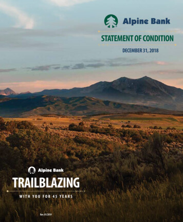
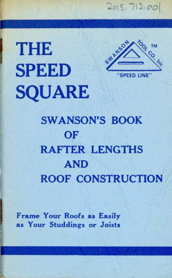
Valley ConstructionThe construction of valleys using prefabricated reducing valley trusses allows the formation of roof intersections withminimum of site-cut infill. The valley trusses are aligned and the topmost braced back to the supporting trusses; diagonalbracing is then fixed and a longitudinal tie at the apex node. Ideally, the lower edge of the bottom chord of the valley frames isbevelled to suit the roof slope of the supporting trusses or fixing thrust battens cut from one piece of timber for economy.Sarking, tiling battens and tiling can then be carried out to line in with the supporting roof.Thrust battens are fixed to the truss raftersto prevent the valley frames from sliding.Loose Hip ConstructionFor spans up to 5.7m overall wall plates, a completelyloose timber infill can be supported by a girdertruss positioned at half the span from theend wall.Girder trussEnd mono trussHip rafterITW ALPINE : TRUSSED RAFTER GUIDE04
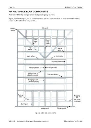
Hip End Construction - StandardThe design has evolved to reduce traditional infill athipped ends to a minimum - thereby keeping site materialand labour costs down.u ss. trStdermIntThe main structural components consist of a multi-ply hipgirder which supports the mono pitch trusses and hiprafters forming the hip.eeserirdgHipeSidSingle hip girders are then used to infill up to the first fulltruss at the end of the ridge, generally at the same spacingas the full trusses for economic use of components. Themono-pitch trusses and the single hip girder trusses maybe supplied with extended rafters for site fixing to the htcpitrussrsfterackoesAlternatively, the extension rafters may be omitted toallow for site fixing of loose, pre-cut jack rafters.Truss shoes are used for supporting themono pitch trusses on the hipgirder truss.Hip girderHip rafterbirdsmouthedover wallplateJack rafterHipboard / Haunch(Hip rafter birdsmouthedover girder top chord)Standard truss clip(wallplate omitted)ITW ALPINE : TRUSSED RAFTER GUIDE05Truss shoe supporting monos& loose ceilings joists(all nail holes used with 3.75 x 30mmsquare twisted nails )
Hip End Construction - Multiple GirdersSimilar to the Standard Hip End in basic concept, thismethod is suitable for larger spans, up to about 15m. Twoor more multi-ply girders are used, with flat top infilltrusses in between, to maintain the standard trussspacing.The mono pitch rafter extensions/jack rafters areeconomically designed to suit the truss rafter size, and aresupported as specified by posts from the substructure.donMEnssssessetru te tru.driaStdeedgirerm hip sestnIsryda te truonSec edia irdergermInt ry aoesssExtended rafters sitetrimmed to hip rafterHip girderMono-pitch trussesJack raftersFraming anchor fixed each sideof the girder trusses(all nails holes used with 3.75 x 30mmsquare twisted nails)Truss shoe supporting monos &loose ceilings joists(all nail holes used with 3.75 x 30mmsquare twisted nails)ITW ALPINE : TRUSSED RAFTER GUIDE06
Barn Hip ConstructionThis form of hipped end takes its name from the traditional barn roof, wherein the gable end is built up above the wall plateline, but terminates below the ridge position. A part-hip is thereby formed.To accommodate this roof shape, flat-top trusses are used over the length of the part-hip, with the usual hip rafterincorporated to complete the roof line.No girder or multi-ply trusses are required in the construction as the standard spacing of truss components continues to thegable end.Flat topped trussesbetween gable & full trussesNormally the flat-top trusses would be made to the heightof the gable with the rafter extended on the intermediatetruss frames. Alternatively they may reduce in height from theapex forming a step down hip.Part or Bonnet Hip ConstructionThis variation to a normal hip end depicts a rural style termination at the end of the ridge, exposing a vertical triangle abovethe normal hipped end. The construction is very simple, using a compound truss at the "bonnet" position with the monopitch trusses supported from this compound. The hip rafters would be cut and positioned as for normal hipped ends.Exposed triangle atend of ridged roofCompound ormulti-ply trussMono-pitch trussesITW ALPINE : TRUSSED RAFTER GUIDE07
Hip Corner ConstructionMono valley derermirdIntip ghrymaPristerrafkce terrafHipsseITW ALPINE : TRUSSED RAFTER GUIDE08
Hip corners are formed in a similar way tothe other hips but with a Howe girdertruss to support one end of the hiptrusses.The Howe girder truss maynot be required if a loadbearing wall linesthrough with thewallplate of themain roof.Howe girderHip rafterHowe girder trusssupporting hip girdersand standard trussesMono pitch trussesextend to girderPrincipal truss shoesupporting primary hip girderHeavy duty truss shoesupporting secondary hip girderITW ALPINE : TRUSSED RAFTER GUIDE09
Scissors ConstructionDue to the elevation of the bottom chord, some degree of horizontal movement or force will be generated at wallplate levels.Research into normal domestic masonry wall construction has shown that up to 12mm of total deflection can be tolerated bythe walls. Designs are therefore constrained by this limitation.The use of ITW Alpine glide shoes, which allows reasonable horizontal movement across the walls without imposinghorizontal thrust, assists in accommodating horizontal deflection.Building Designers should carefully consider any wall restraint required when using Scissor or Raised Tie trusses.Raised Tie ConstructionTW964 Glide shoe(all nails holes used with 3.75 x 30mmsquare twisted nails )ITW ALPINE : TRUSSED RAFTER GUIDE10
Dog Leg IntersectionPurlin supportedon ledger which is fixedto face of girder trussesBinder supported from centregirder in angled hangerIntersection set outfrom fascia linesPurlins and binders supportedon bolted or nailed ledgers,purlin struts or steel hangersJack rafters and ceiling joistsITW ALPINE : TRUSSED RAFTER GUIDE11
Room in the Roof - Roof LightPurlinsFor normal roof spans, up to around 9mand larger spans with internal loadbearing walls the truss members can beeconomically designed to carrydomestic loading.Compound or multi-plyRoom-in-the-Roof trussRoof Light constructionmay be cut on site orprefabricatedFor typical dormer windows,traditional purlins supported onmulti-ply trusses carr y theintermediate infilling over thedormer.LedgerThe rafters and extension ceilingties are nailed on, to form theflat roof over the dormerwindow.For larger spans and those withintensive trimmed openings, latticedpurlin beams are required. These aresupported on end and transverse walls and providemaximum floor space.Room in the Roof - Staircase TrimmingFor stairwells, multi-ply trusses or support walls arerequired each side of the opening and binders are fixedas required to support the floor joists and roof infill.The staircase opening should then be trimmed inthe traditional manner.PurlinsInfill raftersTrimmers and PurlinsGirder trussStaircase trimmersITW ALPINE : TRUSSED RAFTER GUIDE12
Chimney & Trap Hatch TrimmingSmall chimneys and hatchesmay be accommodated withinthe standard truss spacing.Progressive details are used toaccommodate chimney andhatches up to twice thestandard truss spacing.Trusses must be at least40mm clear of the stackPurlinStructural postBinderSTrap hatch detail(rafters / webs omitted for clarity)BCup to 2 x SBB must be not more than 2S - C where S isthe standard spacing.ITW ALPINE : TRUSSED RAFTER GUIDE13S
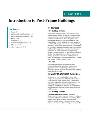
Gable Wall Restraining StrapsRestraining straps at rafter levelNoggin nailed between trusses30 x 5mm thick galvanized steel strapPack between truss and gable wallRestraining straps must be installed to transmit wind loads on walls into the roof structure, and give stability to the walls.In the absence of any specific guidance from the building designer, connections should be made with 30 x 5mm thickgalvanized steel straps fixed to at least three trusses and noggins with 3.35 x 50mm long galvanized wire nails as shown. Ongable walls they should be spaced at not more than 2m centres at rafter and ceiling tie level.Restraining straps at ceiling joist levelStrap to reach uncut blockPack between truss and gable wallNoggin nailed between trusses30 x 5mm thick galvanized steel strapITW ALPINE : TRUSSED RAFTER GUIDE14
Party Wall Restraining StrapsRestraining straps must be installed to transmit longitudinal bracingforces along the roof structure and to give stability to the walls. Inthe absence of any specific guidance from the building designer,connections should be made with 30 x 5mm thick galvanizedsteel straps fixed to at least three trusses and noggins with3.35 x 50mm long galvanized wire nails as shown. Partywalls should have restraining straps at ceiling tie levelsspaced at not more than 2m centres, with the strapconnected to three or more trusses on each side of thewall. Straps may also be required at rafter level totransmit longitudinal bracing forces.Party walls should be stopped 25mm below the topsof rafters. Layers of non-combustible compressible fillsuch as 50mm mineral wool should be placed aboveparty wall to provide a fire stop.If the tiling battens are required to be discontinued over aparty wall, then lateral restraint must be provided inaddition to that required to transfer longitudinal bracingforces. This should consist of straps (or equivalent) adequatelyprotected against corrosion, with a minimum cross sectional area of50sq. mm. These straps should be spaced at not more than 1.5m centres,and be fixed to three rafter members and noggins on each side of the party wall by3.35mm diameter galvanized nails with a minimum penetration into the timber of 32mm.Before using this detail the Building Designer should satisfy themself that it meets the requirements of all regulatory bodies concerned with the project.Gable LadderswidthBarge boards & soffits arenailed directly onto thegable ladderInternogginwhere requiredLast trussShould the width exceed themaximum span allowed for the tilebattens then internoggins should be built intothe ladder. The width should not exceed twice thetruss spacing or 1200mm and the last truss should be spacedback from the gable as shown (see section).In cases of large width or eaves overhang and in areas of high wind speeds,the Building Designer should consider the effect of wind loading on the gableoverhang which could require holding down straps to prevent uplift.ITW ALPINE : TRUSSED RAFTER GUIDE15Gable ladders to befixed to last truss withnails at 400mm centres
Bracing TypesRDPermanent bracing can be constructed from either solidtimber (minimum size 22 x 97mm or 38 x 89mm), or asuitable sheathing material (sarking). BS5268 : Part 3 statesthat bracing timbers should be free of major strengthreducing defects. Timber bracing should be fixed using two3.35mm diameter galvanized round wire nails at eachcrossover point. The length of the nails should be 65mm for22/25mm bracing & 75mm for 38mm bracing. The maintypes of bracing include :-LRRBLRRafter Diagonal Bracing(RD). This is bracing fixed to the underside of the rafter. Itprovides lateral stability to the roof structure and inconjunction with the total roof diaphragm, transfers windloads to shear resisting walls.CBLongitudinal Bracing(LR/LT/LTB). This is bracing fixed at each joint excludingsupport locations. It acts in conjunction with the rafterdiagonal bracing to provide lateral stability to the roofstructure and provides essential stability at the truss nodesfor use in the structural analysis.RDChevron Bracing(CB). This is diagonal bracing fixed to internal members. Itprovides additional stability to the complete roof system.Such bracing is required on duo-pitch roof profiles in excessof 8m and for mono-pitch roof profiles in excess of 5m.LTBRestraining Battens(RB). These are longitudinal braces fixed to web members toprovide lateral restraint to those members (where requiredfrom truss calculations).The Building Designer should note that the bracing shown,which is in accordance with Annex A of BS5268 part 3, onlyprovides stability for the trusses. If additional restraint isrequired for the walls then specially designed bracing willneed to be provided. Typical examples of this are longunbuttressed lengths of masonry walls or high walls. Thereis guidance given on limiting dimensions in Part A of theBuilding Regulations, or the walls may be designed inaccordance with BS5628. The maximum truss spacing is600mm, and plasterboard or some other equivalent ceilingmaterial should be used. It is essential that these importantconstruction details, among others, are considered carefullyduring the building design process.ITW ALPINE : TRUSSED RAFTER GUIDE16RDCB
Raised Tie BracingLongitudinal bracingmembers to abut tightlyevery gable & party wallChevron bracingRafter diagonal bracingRafter bracing mustextend to wallplateBPlasterboardBSection A - AGable endRafter diagonal bracingAAMultiple trussesat openingRafter bracePermanent stability bracing should be installed inaccordance with the design drawings.TrussRafter diagonal bracing should extend to contactthe wallplate. This may be timber or suitable rigidsarking.Where the design drawings show either plywoodbracing or rigid sarking to the upper surface of therafters, ensure that it is fixed as specified.PlasterboardBattens are to be provided at slopingceiling positions to clear rafter bracingSection B - BIn all roofs using raised tie trusses, fix plasterboard,sheathing or an equivalent diaphragm to theceiling tie and extended rafters.(detail where timber brace is used under rafter extension)ITW ALPINE : TRUSSED RAFTER GUIDE17
Room in the Roof BracingTo comply with Building Regulation the floor area should be strutted out in between the joists. Two methods are commonly inuse: 1 - Herring bone strutting can be used where the truss spacing is less than 3 times the joist depth & consists of a cross of38 x 38mm timber cut tightly to the face & skew nailed into position, 2 - Solid strutting may be used in all situations & consistsof 38 x 0.75 depth of joist. The timber must be a good fit, nailed top & bottom.For attic rooms less than 2500mm strutting is not required, between 2501 & 4500 use one row positioned mid span. Between4501 & 5500 use 2 rows at third span positions. When the room width exceeds 5501 install as many rows as necessary so thatthe spacing is not greater then 2250.9mm plywood nailed to 50 x 50mmframe and fixed between rafters.Longitudinal bracing members toabut tightly every gable & party wallRafter diagonal bracingChevron bracing to websSolid blocking or herring bone strutting as specified aboveSection A - AGable endRafter diagonal bracingAAChevron bracingto websPlywoodBefore using this detail the Building Designer should satisfy themself that it meets the requirements of all regulatory bodies concerned with the project.ITW ALPINE : TRUSSED RAFTER GUIDE18
British Standard Bracing - Duo PitchSection A - APart view on arrow CLongitudinal bracingmembers to abut tightlyevery gable & party wallRafter diagonal bracingRafter diagonal bracelap-jointed if requiredIdeally 45deg but not lessthan 35 nor greater than 55 BBGable endChevron bracing to websRafter diagonal bracingNail to wallplateDetail DA600mm long timber splice platesame size as bracing timbers. Fixusing minimum of 4 No. 3.35dia. galvanized nails each side xminimum nail length (equal tobracing thickness 32mm).ADetail DRidgeGable endSection B - BGable endChevron brace to be atapprox 45 and nailed toat least 3 trussesLongitudinal bracePlan of rafter diagonal bracing layout(narrower fronted detached roof)Gable endPlan of rafter diagonal bracing layout(wide fronted detached roof)RidgeSeparating wallMaximum of 2 trussesbetween chevron bracingNote 1: Chevron bracing shown is not required on internal members of truss for spans of 8m or less.Note 2:denotes longitudinal bracing not required when the criteria described in item l(2) of Appendix A of BS5268 Pt.3 are met.ITW ALPINE : TRUSSED RAFTER GUIDE19
British Standard Bracing - Mono PitchSection A - APart plan C - CLongitudinal bracing members toabut tightly every gable & party wall(using 4 on 3 mono trusses)(at gable wall)DRafter diagonal bracingBCCLongitudinal bracing member lapjointed if required.Members to tightly abut everygable and party wall.DBChevron bracing to websGable endAlternative direction of Rafter diagonal bracingrafter diagonal bracingSection B - BChevron brace to be atapprox 45 and nailed toat least 3 trussesGable endLongitudinal braceSection D - DAAWeb diagonal bracingLongitudinal braceNailed to wallplateChevron bracing to websGable endMaximum of2 trusses betweenchevron bracingFor spans in excess of 8.0madditional chevron bracing willbe requiredSectionSection(using 3 on 2 trusses)(using 3 on 3 trusses)Note 1: Chevron bracing shown is not required on internal members of truss for spans of 8m or less.Note 2:denotes longitudinal bracing not required when the criteria described in item l(2) of Appendix A of BS5268 Pt.3 are met.ITW ALPINE : TRUSSED RAFTER GUIDE20Gable end
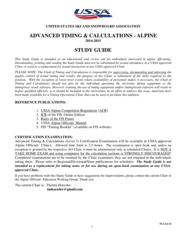
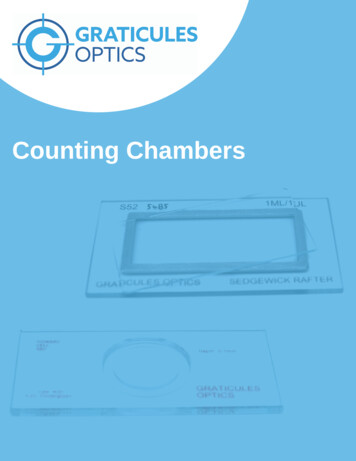
Water Tank Support DetailsTank standDetail ABearer ‘a’S3SS2S3Bearer ‘b’2S3Bearer ‘c’S3S Trussed rafter spacingSIZES FOR SUPPORT MEMBERSTank capacity tomarked waterlineDetail A not morethan 300 litres on4 trussed raftersDetail B not morethan 230 litres on3 trussed raftersMinimum member size (mm)a and cbMax. trussed rafterspan for fink (m)Max. bay size forother configurations (m)47 x 722/35 x 97 or1/47 x 1206.502.2047 x 722/35 x 120 or1/47 x 1459.002.8047 x 722/35 x 14512.003.8047 x 721/47 x 976.502.2047 x 722/35 x 97 or1/47 x 1209.002.8047 x 722/35 x 120 or1/47 x 14512.003.80Note: The timber used should be of strength class C16 or better as specified in BS5268 part 2.ITW ALPINE : TRUSSED RAFTER GUIDE21
Glossary of TermsApex/PeakThe uppermost point of a truss.Duo/dual pitch trussA truss with two rafters meeting at the APEX but not necessarily havingthe same PITCH on both sides.Attic truss/room-in-the-roof.A truss which forms the top storey of a dwelling but allows the area to behabitable by leaving it free of internal WEB members. This will becompensated by larger timber sizes elsewhere.EavesThe line where the rafter meets the wall.Extended Rafter.See RAISED TIE TRUSS.BargeboardBoard fitted to conceal roof timbers at GABLE END.FasciaHorizontal board fitted along the length of the building to the edge of thetruss overhangs.BattensSmall timber members spanning over trusses to support tiles, slatesetc.BearerA member designed to distribute loads over a number of trusses.Fink TrussThe most common type of truss used for dwellings. It is duo-pitch, therafter having the same pitch. The webs form a letter W.BearingThe part of a truss receiving structural support. This is usually aWALLPLATE but can be an internal wall etc.Gable EndThe end wall which is parallel to the trusses and which extends upwardsvertically to the rafters.BinderA longitudinal member nailed to trusses to restrain and maintain correctspacing.Hip EndAn alternative to a GABLE END where the end wall finishes at the sameheight as the adjacent walls. The roof inclines from the end wall, usually(but not always) at the same PITCH as the main trusses.BirdsmouthA notch in the underside of a RAFTER to allow a horizontal seating at thepoint of support (usually used with RAISED TIE TRUSSES).Hip SetThe trusses, girders and loose timbers required to form a hip end.BlockingShort timbers fixed between chords to laterally rstrain them. They shouldbe at least 70% of the depth of the CHORDS.Horn/nibAn extension of the ceiling tie of a truss (usually monos or bobtailedtrusses) which is built intoBottom chord/Ceiling TieThe lowest member of a truss, usually horizontal which carries the ceilingconstruction, storage loads and water tank.Imposed LoadThe load produced by occupancy and use including storage, inhabitants,moveable partitions and snow but not wind. Can be long, medium orshort term.BracingThis can be Temporary, Stability or Wind Bracing which are describedunder these headings.Internal MemberSee WEB.Building DesignerThe person responsible for the structural stability and integrity of thebuilding as a whole.IntersectionThe area where roofs meet.Jack RafterAn infill rafter completing the roof surface in areas such as corners of HIPENDS or around chimneys.CantileverThe part of a structural member of TRUSS which extends beyond itsbearing.Live LoadTerm sometimes used for IMPOSED LOADS.Chevron BracingDiagonal bracing nailed to the truss in the plane of the specified webs toadd stability.Longitudinal Bracing.Component of STABILITY BRACING.Dead LoadThe load produced by the fabric of the building, always long term (seeDESIGN LOADS).Loose TimberTimbers not part of a truss but added to form the roof in areas wheretrusses cannot be used.DeflectionThe deformation caused by the loadsMono-pitch truss.A truss in the form of a right-angled triangle with a single rafter.Design LoadsThe loads for which the unit is designed. These consider the duration ofthe loads long term, medium term, short term and very short term.ITW ALPINE : TRUSSED RAFTER GUIDE22
NailplateMetal PLATE having integral teeth punched from the plate material. It isused for joining timber in one plane with no overlap. It will have anaccreditation certificate and will be manufactured, usually, fromgalvanised steel. It is also available in stainless steel.Spandrel PanelA timber frame, triangular panel forming gable wall above ceilingline.SpliceA joint between two members in line using a NAILPLATE or glued fingerjoint.NodePoint on a truss where the members intersect.StrapMetal component designed to fix trusses and wallplates to walls.NoggingsTimber pieces fitted at right angles between the rafters and ceiling ties toform fixing points.StrutInternal member connecting the third point and the quarter point on aFINK TRUSSS.OverhangThe extension of a rafter or ceiling tie of a truss beyond its support orbearing.Part ProfileA truss type formed by truncating a normal triangular truss.Stub EndSee PART PROFILE.PitchThe angle of the rafter to the horizontal, measured in degrees.Temporary BracingAn arrangement of diagonal loose timbers installed for safety duringerection. Often incorporated with permanent STABILITY and WINDBRACING structures.PurlinsTimber members spanning over trusses to support cladding or betweentrusses to support loose timbers.Timber Stress GradingThe classification of timber into different structural qualities based onstrength (see BS4978: 1996).QueenInternal member (WEB) which connects the APEX to a third point on aFINK TRUSS.TrimmerA piece of timber used to frame around openings.Trussed Rafter DesignerThe person responsible for the design of the TRUSSED RAFTER as acomponent and for specifying the points where Bracing is required.Rafter/Top chordThe uppermost member of a truss which normally carries the roofcovering.Truss clipA metal component designed to provide a safe structural connection oftrusses to wallplates. Also to resist wind uplift and to remove the damagecaused by SKEW NAILING.Rafter Diagonal BracingComponent of STABILITY BRACING.Raised Tie TrussA truss which is supported at a point on the rafter which is beyond thepoint where the rafter meets the ceiling tie.Truss ShoeA metal component designed to provide a structural connection andsupport for a truss to a girder or beam.Return SpanThe span of a truss being supported by a girder.Uniformly distributed load (UDL)A load that is uniformly spread over the full length of the member.RidgeThe line formed by the truss apexes.Valley BoardA member raking from incoming RIDGE to corner in a valleyconstruction.Roof DesignerThe person responsible for the roof structure as a whole and who takesinto account its stability and capability of transmitting wind forces on theroof to suitable load-bearing walls.Valley Frames/SetInfill frames used to continue the roofline when roofs intersect.ScabAdditional timber fitted to the side of a truss to effect a localreinforcement, particularly in RAISED TIE TRUSSES.VergeThe line where the trussed rafters meet the gable wall.WallplateA timber member laid along the length of the load bearing walls tosupport the trusses.Setting out PointThe point on a truss where the undersides of the rafter and ceiling tiemeet.SoffitBoard fixed underneath EAVES overhang along the length of the buildingto conceal timbers.WebsTimber members that connect the rafters and the ceiling tie togetherforming triangular patterns which transmit the forces betweenthem.SpanSpan over wallplates is the distance between the outside edges of thetwo supporting wallplates. This is usually the overall length of the ceilingtie.Wind bracingAn arrangement of additional timbers or other structural elements in theroof space, specially designed to transmit wind forces to suitable loadbearing walls.ITW ALPINE : TRUSSED RAFTER GUIDE23
ALPINEThreemilestone, Truro, Cornwall, TR4 9LDtechnical enquiries : 01872 245456general enquiries : 01872 245450facsimile: 01872 245451www.itwalpine.co.ukA division of ITW Limited.Registered Office: ITW Limited, Admiral House, St Leonard’s Rd, Windsor, Berkshire. SL4 3BLRegistered in England No. 559693 ITW Alpine 2008No part of this publication may be reproduced without prior permission from ITW Alpine.Last updated 10-04-08Disclaimer NoticeAll descriptions and illustrations in this technical manual are intended for guidance only andshall not constitute a " sale by description ". All dimensions given are nominal and ITW Alpinemay change the information, products and specifications from time to time for a variety ofreasons, without prior notice. This information in this technical manual is provided " as is " atthe date specified above. Updates will not be issued automatically. This information is notintended to have any legal effect, whether by way of advice, representation or warranty(express or implied). ITW Alpine accepts no liability whatsoev
Hip rafter Valley Construction The construction of valleys using prefabricated reducing valley trusses allows the formation of roof intersections with minimum of site-cut infill. The valley trusses are aligned and the topmost braced back to the supporting trusses; diagonal bracing is then fixed and a longitudinal tie at the apex node.