Transcription
CSR ROOFING ARCHITECTURAL MANUALINSTALLATIONThis manual has been prepared by CSR ROOFING to assist the builder,the architect and the installer to specify, detail, prepare and install roof tiles.While it is not possible to list and detail every condition that may be encountered,CSR ROOFING will assist and advise on any special situations that may occur.
ContentsBattens1Bedding and Pointing1Sarking/Underlay2Laying of Tiles4SECURING OF TILES5securing accessories6caring for your roof11LAYING TILESTiles should be laid and secured in accordance with AS 2050 and NZS 4206 “Installation of Roof Tiles.”This section details CSR Roofing’s security installation specifications. These specifications have been developed fromregional experience, research and practical application, in context of the following relevant Building Codes and Standards:a) AS 2050 “Installation of Roof Tiles”b) AS/NZ4200.2 “Installation of materials suitable for use as Pliable Building Membrane”While regional variations exist, your roof tiling contractors will:1. Install an appropriate fall protection system to meet Occupational Health and Safety guidelines(subject to regional practice)2. Install tile battens3. Install sarking or underlay (as required)4. Install tiles and accessories using a recommended security method5. Bed and point ridge and hip joins6. Install fire-resistant batts over party walls (as required)7. Fix anti-ponding boards (subject to regional practice)8. Clean the roof of footmarks and loose debris
CSR ROOFING ARCHITECTURAL MANUALBATTENSThe installation of battens to rafters mustJoints in Battenscomply with the loading requirements ofBatten joints should be staggered overClause 1.4.1 of AS 2050.the roof so that three consecutive battensSecurity fixing to Rafter»»Fixing for tiles to battens and for battens(NZ – 2 consecutive battens) are not jointedon the same rafter. All joints in battens mustmeet in the centre of trusses or rafters, andto steel frame should be non-ferrousnot be joined over girder trusses. Battensstainless steel or steel with an appropriateshould be nailed.corrosion-resistant coating»»Clout nails must comply with AS 2334Hip and Valley Jointsand NZS 4206, have a minimumWhere battens intersect with hip board anddiameter of 2.8mm, and have avalleys provide firm support.minimum penetration of 15mm into therafter (or 18mm in New Zealand)»» Self-drilling screws used to fix battensSteel BattensRefer to the steel batten suppliers for themust comply with AS 3566 and NZStechnical fixing specification. Particular4206consideration should be paid to battenspacings as battens may be installed bytrades other than the roof tiler.Pointing MortarAustralian Standard 2050 Installation ofCement mortar bonding shall not be usedroof tiles requires as a minimum.as the mechanical fixing method. It canbe used however in conjunction with some“Cement mortar for bedding (1:4) 1other form of mechanical fixing.cement, 4 0.4 sand.”»»Pointing mortar when used shall be 3-1mix, 3 clean sharp sand, 1 cement, withThe use of other additives such as “Lime,Fire clay” is permitted at the followingoxides or pigments to suit.»»Flexible, premixed pointing is availableratios:and in most cases is rated as a»»Lime composition bedding mortarmechanical fixing. Check with the(1:1:6). .1 cement, 1 0.25 lime, 6 0.6 sand.»»Fire clay when used, replaces an equalmanufacturer for confirmation of status.Bedding and Pointingamount of sand therefore, if 1/2 aThe pointing should be neatly trowelled,measure of fire clay is used the ratiowith an even finish throughout. Collar/cuffswould be (1: 0.5: 3.5) .1 cement, 0.5 should be pointed (if Flexible pointing is the0.005 fire clay, 3.5 0.3.5 sand.mechanical fixing then it is mandatory toFire clay is not a replacement for cement.point collars/cuffs.)The use of plasticizer’s and products thataerate mortar is not permitted as theseproducts weaken the mortar.1SECTION 5Bedding Mortar MixINSTALLATIONBEDDING AND POINTING
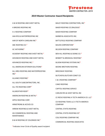
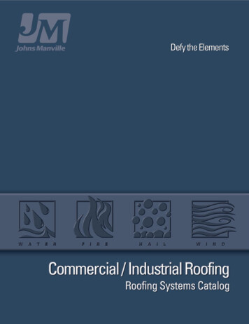
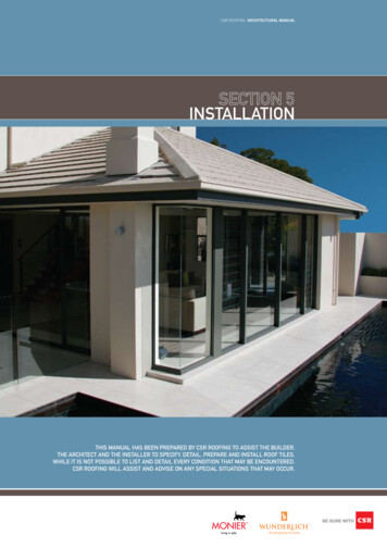
CSR ROOFING ARCHITECTURAL MANUALSARKING/UNDERLAYSarking/Underlay hastwo key purposes:Sarking/Underlay is a reflective, water»» Where condensation may be an issueresistant foil laminate material (or self»» To minimise the build up of dust in thesupporting building paper in NZ) that sitsa) the reflective foil finish acts as asnugly beneath the batten of a tiled roof.radiant heat barrier, reflecting upUnderlay is a pliable building membraneto 95% of radiant heatthat sits snugly beneath the batten of ab) where tiles are broken or becomedislodged, Sarking/Underlayacts as a secondary barrier towater entry, particularly at lowerroof pitches. As such, Sarking/Underlay is mandatory on roofstiled roof.»» significantly increase life of the Sarking/Underlay»» one side is treated with anti-glareceiling cavity»» At the change of roof pitch joint from thatjoint to the eaves guttersurfacing reducing reflection»» maximum flammability index rating of 5»» Where rafter length exceeds 4.5m atminimum pitchCSR Roofing recommends the use of»» Under raked ceiling or exposed raftersSarking/Underlay in all roofs.There are a number of circumstancesFor Australian conditions, CSR RoofingLayingwhere the use of Sarking/Underlay isrecommends the use of a mediumThe reflective side of Sarking/Underlayrecommended, or mandatory:duty polymer based material known asshould be laid face down.recommendationsEnviroseal, manufactured by CSR Bradford.with long run rafters or low pitch.CSR Bradford Enviroseal is designedOver-lapping Sarking/Underlayextreme weather conditions are probablespecifically for Australian conditions andSarking/Underlay should overlap not lessi.e. cliff tops, open exposed sites orexceeds the requirements of AS/NZSthan 150mm, ensuring the upper layer restsbushfire prone areas4200.1 Pliable Building Membranesover the top of the lower layer of Sarking/»» Where local regulatory authorities suggest»» In bushfire prone areas, to preventUnderlay. At the end of a roll of Sarking/The advantages of Enviroseal are:Underlay, the layers of Sarking/Underlay»» resistance to tearingshould overlap by a minimum of one rafter41m/s (ie. greater than C1 or N3) and»» acts as a vapour barrierspacing. Sarking/Underlay should sag no44m/s in NZ.»» significantly increased strength overmore than 40mm between the rafters.embers entering the roof space»» Where design wind velocity exceeds»» Immediately underneath and extendingpaper-based Sarking/Underlayto the gutter around solar hot watercollectorsSARKING/UNDERLAYINSTALLATIONTile BattenSecurity Pad(recommended)Anti-ponding BoardSarking/UnderlayGutter2SECTION 5Sarking/Underlay25 -50mm overlapRafterExterior WallEaves Lining / SoffitMetal or TimberFasicaVariable
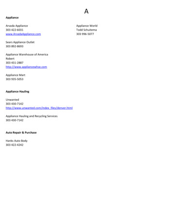
CSR ROOFING ARCHITECTURAL MANUALObstacles in the RoofSarking/Underlay Supportof Sarking/Underlay support or safety meshHot Flue: The Sarking/Underlay should beSubject to regional specifications, an approvedis performed by other trades as referred to inInstallationcut back, allowing a clear space of 50mmanti-ponding board is recommended on roofsAS 2050 Appendix B.Sarking/Underlay must be installedPenetrations: The Sarking/Underlay shouldwith a low pitch. (Refer to the prior section onbe turned up and sealed to divert waterAnti-Ponding Boards.)to CSR Roofing fixing specifications,Sarking/Underlay at ValleysSarking/Underlay is held in place by fixingfrom any projection in the roof. Where afascia batten is used in place of a fasciaWhere rafter centres exceed 600mm, thea valley batten parallel to the valley gutter.board and there is no gutter, the Sarking/Sarking/Underlay should be adequatelyThe Sarking/Underlay should overlap theUnderlay material should be neatly cut backreinforced. Where the rafter centres exceedvalley by no more than 25mm or be rolledto the outside edge of the fascia batten.900mm, supporting the Sarking/Underlayover or cut at the valley batten. If Sarking/or using an approved heavy grade Sarking/Underlay projects too far into valley the roofUnderlay becomes mandatory. Installationis likely to leak.Use of Security Padsin accordance with AS/NZ 4200.2.Sarking/Underlay is mandatorywhere wind exceeds 41m/s orN3 as per AS2050To avoid constant flexing and to increasethe life of the Sarking/Underlay materialthe use of security pads or anti-flap padsis recommended. Security pads should beinstalled in a staggered pattern under eachsecond row of battens between each pairof rafters.Sarking/Underlay at EavesTo allow effective run off into gutter,Sarking/Underlay should extend over thefascia board by a minimum of 25mm and amaximum of 50mm.INSTALLATIONVALLEYSECTION 53
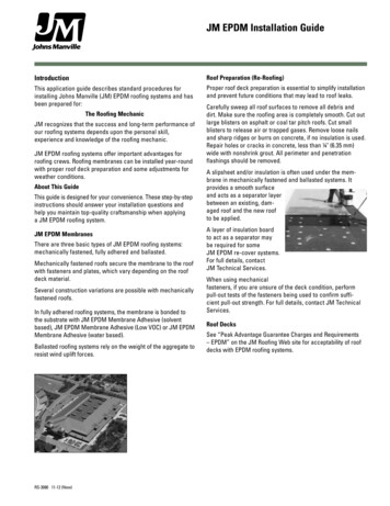
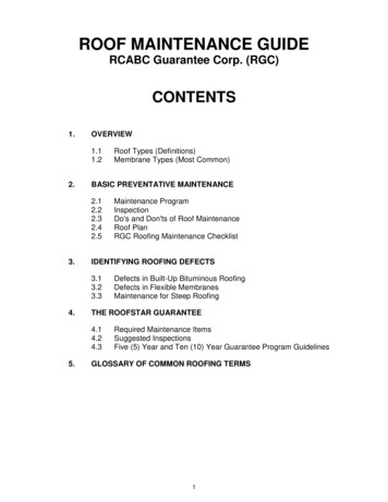
CSR ROOFING ARCHITECTURAL MANUALLAYING OF TILESTiles should be laid and securedin accordance with AS 2050 andNZS 4206.LoadingFirst CourseThe entire roof must be battened andThe first course of tiles should projectsarked before tiles can be loaded ontoapproximately 50mm over the fascia andthe roof.into the gutter.In buildings with exposed rafters, or a rafterLayinglength greater than 6m, tiles should beAll tile courses should be alignedloaded onto the structure from each side tohorizontally, vertically and diagonally, toensure their weight is evenly distributed.ensure a straight finish at the roof edge andto achieve the best look for the roof.Tile set outTiles can be laid either cross or straightbonded to createa differentfor the spacingCoverlengthlookor battenFirst course set outroof.BlendingVarying shades of colour are a feature ofterracotta tiles, therefore layout is critical.Blended roofs involve the mixing of anumber of tile colours in the roof as theyare laid.After about 75 or 100 tiles have been laid,a visual inspection of the roof should bemade to ensure tile courses are straight, andthat colour variations are evenly distributed.This procedure should be repeated atINSTALLATIONregular intervals during tile installation.SECTION 54Straight bondedcross bonded
CSR ROOFING ARCHITECTURAL MANUALSECURING OF TILESTile ClipsCSR Roofing security fixing system includesa variety of clip fittings.3Steep and Vertical pitchAll tiles should be mechanically fixednailsIn extreme conditions, clips is the preferredNails should be non-ferrous ormethod of mechanical fixing in Australia.galvanised, of 2.8mm diameter,with length to penetrate the rafterbetween pitches of 40–70 degrees.Standard Tile Clip“Mechanical fixing” may be achievedTiles at pitch greater than 70 degrees mustat least 15mm (18mm in NewThe Standard and Heavy Duty clip, availablethrough nailing every tile, screwing every tilebe double mechanical fixed and sarked.Zealand). The nail requirementsin either galvanised or plastic.or clipping every tile. The specific methodrelevant to the timber used andused varies by region. It is recommendedwind loadings are specified inthat local advice is sought.AS 2050.2.4. and NZ 4206.12Eave tile ClipsEaves clips reduce the possibility of tilesCSR Roofing’s Security Fixinglifting at the eaves in high wind areas.system also offers the useof standard and heavy dutyclips, eaves tile clips, screwsand adhesives. The additionalrequirements relating to theirapplication in Sections 1.34, 1.43STANDARD TILE CLIP2EAVE TILE CLIPS3STEEP PITCH3VERTICAL PITCHand 2.4 of AS 2050.INSTALLATION1SECTION 55
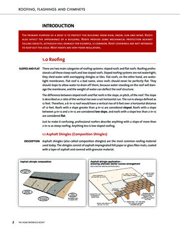
CSR ROOFING ARCHITECTURAL MANUALSECURING ACCESSORIESAccessory TilesRidge and Hip FinishesAfter the main roof tiles have been laid,The roof tiles at the join of a hip must beRidge and hip tiles may be laid usingthe installation of accessory tiles cancut and laid with a maximum of 20mmdifferent methods to create varying lookscommence. CSR Roofing manufacturesbetween the planes.for the ridge/hip line. The following arevarious types of accessories, as detailed insuggested details suitable for hips.the Product Sections of this manual. AllA Hip Starter must be laid to project intojunctions of hip and ridges must be madethe gutter, in line with the nose of the firstweatherproof. Accessories available forcourse of tiles. Alternatively a ridge tile caninstallation are dependent on the profile, thebe shaped to replace a hip starter.pitch and the position of the join in the roof.LayingSecurity Fixing13Standard detail4Mitred Hip DetailConsult your local CSR Roofing office forprofiles suitable for Mitred hips.Ridge and hipAll ridge and hip tiles must be laid in aAs specified in Table 3 (Minimum FixingA continuous metal underflashing isstraight line, allowing for the natural contourRequirements for Tiles and Accessories/installed under the hip tiles.of ridge tiles. The over-lapping of ridge tilesFixing Recommendations), at design windThe underflashing can be in the form of ashould be directed away from the prevailingspeeds above 41m/s or 44m/s (in NZ), everyconcealed gutter. All mitred tiles must bewinds.ridge tile must be mechanically fixed.machine cut and mitred joints filled with aRidgeCut tiles should be supported by galvanisedThe ridge tiles are initially laid onto a bednails spiked to the hip board.suitable sealant.INSTALLATIONSECTION 56Butt Joining/A LineAn alternative to conventional, overlappingof mortar and finished with flexible pointingmaterial.52Steep Pitchridge and hip tiles, butt-joining provides aSteep Pitch Ridge tiles are used on roofssmooth yet defined roofline. A continuousHippitched in excess of 40 degrees.underflashing is required with thisA hip begins with a Hip Starter or ShellA galvanised wire or bitumen-impregnatedtreatment.End, positioned on a bed of mortar at thefoam may be used to reinforce the bed andlower end of the hip.pointing of the ridge, hip or gable.ROOF DETAIL
CSR ROOFING ARCHITECTURAL MANUAL1Ridge and hipRidge CappingContinuousUnderflashing(optional)Bedding & PointingFixingScrewRoof TileRidge BoardBarge BoardTop PlateWall SheathingTile BattenRafter2steep pitch3standard detail5butt joining/A lineRidge CappingHookedNailReinforcing Meshor Bitumen Impregnated rTileRidge BoardTile Battenmitred hip detail7SECTION 54Hip BoardContinuous Poly Dampcourseflashing installed underridge tilesTile BattenA-line ridge(Butt joining)RafterRidge CapMetal or TimberFasicaTileHip Starter
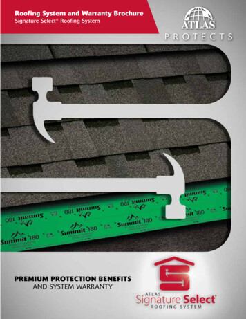
CSR ROOFING ARCHITECTURAL MANUAL6Valley Tile Installation6valley tile InstallationThe valley width is dependent on regionalweather conditions.Under normal conditions, a gap of 75 to100mm between tiles is acceptable. In highrainfall areas, valley tiles should be sealedwith a bitumen impregnated foam. Thevalley gap may be increased to 100mm.In high rainfall areas, valley design anddownpipe position should be designed tosuit the roof as per AS3500.7 ire Walls/InternalFSeperating WallsA fire retardant material should fill the cavityabove the fire wall up to the underside»» A bedding of cement mortar is placedof the tiles. In NZ, the fire retardantWhere winds exceed 41m/s, sarking ismaterial and batten is replaced with amandatory. In New Zealand, these windonto the strip. Tiles with a clean edge arefired rated mortar or bedding. Except forspeeds are 41m/s and 44m/s respectively.positioned along this bed and pointed75mm x 50mm roof batten or less, timberIf further clarification is required, it iswith an appropriately coloured flexibleor other combustible building element,advisable to contact your local CSR Roofingpointing. Pointing should be finished withshould not pass through the fire-wall.office for advice.a slight incline toward the outer edge and8Counter BatteningBarge/Gabledevoid of trowel marks.10A B Barge/Gable FinishWhenever a lining material is installed overFor gable roofs, it is good practice for roofrafters – commonly rerferred to as ‘Closetiles to finish with equal length of tile atThe top of the barge board should be flushBoarding’ counter battens wil need to beboth ends.with the top of the tilt batten.underlay can be laid in accordance withA gable end (verge) can be set according toEither standard or rounded barge tiles arethe relevant Australian Standard AS4200.2local requirements and exposure conditions,laid over the gable end (with or without aand also provide a base for the tile battensand include:bedding between the tiles and the bargeINSTALLATIONinstalled. This will then ensure sarking/SECTION 58tile). The lower end of the barge tiles areto be fixed.9Bush fire protectionBed and Point Finish»» Place a fibre cement bedding stripmechanically fixed (screwed or nailed)according to local specification into theAs per AS 3959, additional fixing100mm wide and 5mm thick over therequirements apply to designated bush firebarge board. The bedding strip shouldhazard areas. State authorities, insurers,project a minimum of 19mm but acountry fire authorities or related bodies,maximum of 25mm beyond the face ofThe top of the barge must be 75mm abovecan identify these high fire hazard areas:the barge board. It is recommended thatthe top of the battens. A suitable metalthe bedding strip is secured into placesoaker should be installed as illustrated.For roofs in these areas,with a timber fillet»» The degree of projection of the bedding»»Sarking/Underlay must be usedstrip should be left to the tiler’s discretion»»Flexible pointing must be usedto ensure finish off with a full tile at all»»Every tile must be securedleft hand gables (where practical). Theunderlap of the tile to all left hand gablesIn Australian locations where high windsare in excess of 41m/s i.e. above N3 or C1,should be removed.»» The barge board must be kept flush withsarking with security pads is recommendedthe top of the batten. This allows the fibreirrespective of roof pitch.cement strip to sit level with the top ofthe batten and barge board.barge board or brickwork.11Concealed/Secret Gutter Finish
CSR ROOFING ARCHITECTURAL MANUAL7Fire Walls8Counter batteningTileTile BattenRafterFire Retardant BattsBed and point finish10 B. Concrete Barge10 A. terracotta gable end11 CONCEALED/SECRET GUTTER FINISHINSTALLATION9Internal Wall9SECTION 5Mineral fibre, or other suitablefire-resisting material, packedto fill any gap between the topof the wall and the undersideof the roof tile.
CSR ROOFING ARCHITECTURAL MANUALBed and point materialsMortar MixThe bedding mortar mix should be a sand-cement mix of four parts bricklayer’s sand to onepart cement. Refer to 2.3 of AS 2050 or NZS 4206.ApplicationThe bedding should be trowelled through the whole joint with an even finish. All tilesadjacent to the ridge and hip should be lightly cleaned and brushed free of loose particles.Flexible PointingFlexible Pointing is a highly pliable yet durable compound which, once cured, forms anincredibly strong bond between the tile and ridge capping. The use of Flexible Pointingyields the following benefits:»» Unlike traditional mortar based pointing, it will bend rather than crack with the movementof the house»» No need to wait for the roof to settle before pointing can begin, allowing the roof to becompleted earlier»» Flexible Pointing saves time and money through a reduction in long term roofmaintenance»» Bond between tile and ridge is so strong that it removes the need for mechanical fasteners»» Will flex and move to allow for the removal and replacement of tiles»» Available in a range of contemporary coloursAs per AS 2050.2, Clause 2.4 above 33m/s, cement mortar should not be used as the solefixing method.ApplicationINSTALLATIONPointing should be coloured to match the roof tiles. Trowel the flexible pointing materialSECTION 510to a thickness of 3–5mm, ensuring that the pointing is in full contact with the edge of thecapping and has a neat, clean finish. Weepholes may be required to allow drainage. All tilesadjacent to the ridge and hip tiles are to be cleaned and brushed free of loose mortar andpointing particles.Roof CompletionTilers should take care to remove all debris from the roof and gutters on completion of thejob. In particular, care should be taken to remove any steel debris, such as nails, which maycause staining of the tiles or premature corrosion of gutters.A final detail check of the roof on completion is conducted to ensure that any broken orcracked tiles are replaced ensuring the roof is fully waterproof.
CSR ROOFING ARCHITECTURAL MANUALCARING FORYOUR ROOFYour roof is required to remain waterproof for a long time after it is installed. In fact, yourCAUTIONroof tiles are structurally guaranteed to perform their function for 50 years* (Please refer toIf your roof needs checking or if youthe guarantee for each product)have a roof leak, it is always bestto employ an expert tradespersonUnderstandably, this guarantee does not cover matters beyond our control, such as:to undertake the work for you, aswalking around on roofs can be»»Damage caused to the roof by other parties, including plumbers,dangerous.»»TV antenna and airconditioning installers etc.»» Falling objects»» Air pollution»» Acts of nature»» Tiles being treated with the wrong chemical or coatings»» Acts of war or terrorismTo ensure your roof remains watertight, roof traffic should be kept to a minimum. Below aresome handy hints to minimise damage to your roof.»»Only access your roof when absolutely necessary and observe safety requirements»»Wear soft sole, non-slip footwear»»Always be aware of weather and conditions, as tiles can be slippery»»Extend your ladder at least 1 metre past the gutter and secure»»Only step on the lower centre of roof tiles»»Secure a walkway of plywood, ladders, planks etc. if heavy traffic is necessary»»To remove objects from the roof. Use a long stick or rake where possible»»Remove roof tiles by kicking the lower centre of the tile towards the ridge»» When performing any maintenance to your roof, it is recommended that you consult aroofing specialist.Also enclosed are some simple hints should you need to repair your roof. When in doubtLeaks are most often confined to small areas and usually occur as a result of one or more ofthe following problems:»»Cracked or broken cement mortar bedding to the ridge or hip cappingCapping should be rebedded or repointed»»Cracked or broken roof tilesIndividual roof tiles should be replaced»»Roof tiles displacedDisplaced tiles should be put back into their proper position»»Blocked drainage channels under the ‘sidelaps’ of individual tilesAny build-up of dirt or debris should be removed»»Flashings blocked, damaged or displacedThese problems should be corrected»»Blocked gutters (including valley gutters) and downpipesThese should be cleaned out11SECTION 5Some facts about tiled roofsINSTALLATIONabout your roof, always consult a roofing specialist.
the roof so that three consecutive battens (NZ - 2 consecutive battens) are not jointed on the same rafter. All joints in battens must meet in the centre of trusses or rafters, and not be joined over girder trusses. Battens should be nailed. Hip and Valley JointS Where battens intersect with hip board and valleys provide firm support. Steel .