Transcription
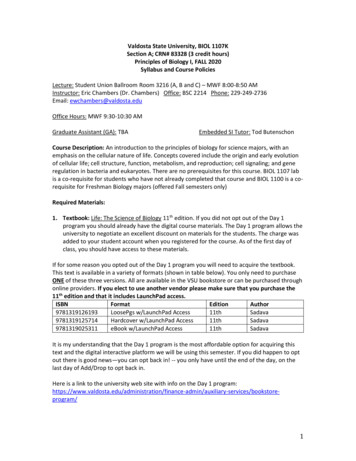
User's GuideSLAU533D – September 2013 – Revised April 2017MSP430F5529 LaunchPad Development Kit(MSP‑EXP430F5529LP)The MSP430 LaunchPad development kit now has USB. The MSP-EXP430F5529LP is aninexpensive and simple development kit for the MSP430F5529 USB microcontroller. It offers an easy wayto start developing on the MSP430 MCU, with onboard emulation for programming and debugging as wellas buttons and LEDs for a simple user interface.Figure 1. MSP430F5529 LaunchPad Development KitSLAU533D – September 2013 – Revised April 2017Submit Documentation FeedbackMSP430F5529 LaunchPad Development Kit (MSP‑EXP430F5529LP)Copyright 2013–2017, Texas Instruments Incorporated1
www.ti.com123456ContentsGetting Started . 4Hardware. 9Software Examples . 28Additional Resources . 48FAQs . 52Schematics . 541MSP430F5529 LaunchPad Development Kit . 12Jumper Requirements Necessary for Software Demo . 53Storage Volume, Mounted from the MSC Interface . 64Files on the Storage Volume . 65Default Text Typed From Button S16ASCII-Art Rocket, Typed from Button S2 . 87EVM Features and Controls . 98Block Diagram . 109MSP430F5529 Pinout . 1110eZ-FET lite Emulator . 1211Onboard USB Bus Path . 1312F5529 LaunchPad Development Kit USB Interfaces . 1413F5529 LaunchPad Development Kit Power SupplyList of 536373839402.Backchannel UART Pathway .Application Backchannel UART in Device Manager .Isolation Jumper Block .Power Block Diagram for Default Configuration With USB Power Only .Power Block Diagram for External 3.3-V Power Source .Power Block Diagram for External 5-V Power Source Without USB Connection .Power Block Diagram for External 5-V Power Source With USB Connection .USB BSL Button .Identifying the USB BSL HID Interface in Device Manager .F5529 LaunchPad Development Kit to BoosterPack Plug-in Module Connector Pinout .Browse to Demo Project for Import Function .When CCS Has Found the Project .F5529 LaunchPad Development Kit Demo Software Organization .MSP430 USB Descriptor Tool .Demo Program Flow .Disable the Watchdog in Pre-Initialization .Waking From LPM0 .Movement of Data in simpleUsbBackchannel: CDC .simpleUsbBackchannel USB Virtual COM Port, Needing a Driver .Device Manager After Both Ports are Enumerated .Movement of Data in simpleUsbBackchannel: HID-Datapipe .Start Device Manager .Device Manager .F5529 LaunchPad Development Kit With DLP-7970ABP NFC BoosterPack Plug-in Module .USB Examples in the USB Developers Package .TI Resource Explorer: Create a New USB Project Wizard .Schematics (1 of 4) .MSP430F5529 LaunchPad Development Kit 3132333539404146464748505154SLAU533D – September 2013 – Revised April 2017Submit Documentation FeedbackCopyright 2013–2017, Texas Instruments Incorporated
www.ti.com41Schematics (2 of 4) . 5542Schematics (3 of 4) . 5643Schematics (4 of 4).57List of Tables1Files on the Storage Volume . 62eZ-FET lite LED Feedback Behavior . 133Isolation Block Connections45678910.Hardware Change Log .Software Examples .Demo Project File and Directory Descriptions.Backchannel Library: Constants to Configure .Backchannel Library: Functions .Clock Settings .How MSP430 Device Documentation is Organized .1727283042424348TrademarksMSP430, LaunchPad, BoosterPack, Code Composer Studio are trademarks of Texas Instruments.IAR Embedded Workbench is a trademark of IAR Systems.All other trademarks are the property of their respective owners.SLAU533D – September 2013 – Revised April 2017Submit Documentation FeedbackMSP430F5529 LaunchPad Development Kit (MSP‑EXP430F5529LP)Copyright 2013–2017, Texas Instruments Incorporated3
Getting Started1www.ti.comGetting StartedRapid prototyping is simplified by the 40-pin BoosterPack plug-in module headers, which support a widerange of available BoosterPack plug-in modules. You can quickly add features like wireless connectivity,graphical displays, environmental sensing, and much more. You can either design your own BoosterPackplug-in module or choose among many already available from TI and third-party developers.The MSP430F5529 16-bit MCU has 128KB of flash memory, 8KB of RAM, 25-MHz CPU speed,integrated USB, and many peripherals – plenty to get you started in your development.Custom USB functionality can be quickly added using the free open-source USB tools and examplesavailable in the MSP430 USB Developers Package. This includes the MSP430 USB Descriptor Tool,which quickly customizes any combination of USB interfaces and automatically generates your USBdescriptors for those interfaces.Free software development tools are also available: TI's Eclipse-based Code Composer Studio IDE(CCS) and IAR Embedded Workbench IDE (IAR), and the community-driven Energia open-source codeeditor. More information about the LaunchPad development kit including documentation and design filescan be found on the tool page at www.ti.com/tool/msp-exp430f5529lp.1.1Key Features 1.2USB-enabled MSP430F5529 16-bit MCU– Up to 25-MHz System Clock– 1.8-V to 3.6-V operation– 128KB of flash, 8KB of RAM– Five timers– Up to four serial interfaces (SPI, UART, I2C)– 12-bit analog-to-digital converter– Analog comparator– Integrated USB, with a complete set of USB tools, libraries, examples, and reference guidesThe eZ-FET lite emulator, with the application ("backchannel") UART. (Now open-source!)Ability to emulate and develop USB applications with a single USB cable, made possible with anonboard USB hubPower sourced from the USB host. The 5-V bus power is reduced to 3.3 V, using an onboard dc-dcconverter.Both male and female 40-pin BoosterPack plug-in module headers, configured for stacking. 20-pinBoosterPack plug-in modules can also be attached.Compatible with the 40-pin BoosterPack plug-in module development tool standard.Kit Contents(1) MSP-EXP430F5529LP LaunchPad development kit(1) USB cable with "micro" connectors(1) Quick start guideIf you intend to write code for the F5529 LaunchPad development kit, you can complete the kit bydownloading the MSP-EXP430F5529LP Hardware Design Files and the MSP-EXP430F5529LP SoftwareExamples from the MSP-EXP430F5529LP tool page.1.3Out-of-Box ExperienceThe F5529 LaunchPad development kit comes programmed with an out-of-box demonstration example.Let's get started!This section only describes how to use the demo. More details about the F5529 LaunchPad developmentkit are given later.4MSP430F5529 LaunchPad Development Kit (MSP‑EXP430F5529LP)SLAU533D – September 2013 – Revised April 2017Submit Documentation FeedbackCopyright 2013–2017, Texas Instruments Incorporated
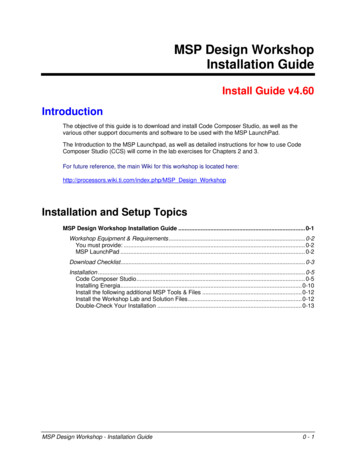
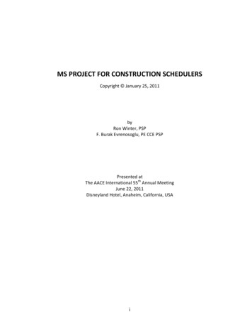
Getting Startedwww.ti.comThe demo works on a Windows PC, Linux PC, or Mac. It requires that (at minimum) the power jumpers(3.3 V and 5 V) on the isolation jumper block be connected. These supply power to the target F5529device. As shipped from TI, these jumpers are connected.Figure 2. Jumper Requirements Necessary for Software Demo1.3.1Step 1: Install a Software Development PlatformThe development platform can be Code Composer Studio IDE (CCS), IAR Embedded Workbench IDE(IAR), mspgcc, or Energia open-source platform. See Section 3.2 for help choosing a platform.The out-of-box demo works without this step, but the host reports that the integrated eZ-FET lite emulatordid not enumerate.(Be aware that the USB API does not yet fully support mspgcc development, but mspgcc does contain theeZ-FET drivers.)1.3.2Step 2: Connect the HardwareConnect the LaunchPad development kit to a host PC using the USB cable included with the LaunchPaddevelopment kit. The demo should work on any recent version of these operating systems. If prompted, letthe PC automatically install software. The install is "silent", which means that the PC's operating systemalready has the drivers it needs.When you connect a USB device to your computer, the computer goes through the enumeration process.During enumeration, the host asks for the device's USB descriptors to learn the device's identity,capabilities, and more. Using the descriptors, the device presents one or more USB interfaces to the host,where each interface is associated with either a pre-defined device class, or a custom driver. The majoroperating systems already ship with drivers for most common device classes, which is why you do notneed to provide them during installation.The F5529 LaunchPad development kit software demo presents two USB interfaces to the host: A Mass Storage Class (MSC) interface, which results in a storage volume A Human Interface Device (HID) interface, which is configured as a keyboardAll major host operating systems already have drivers for these classes.Note: The eZ-FET emulator, application UART, and USB hub also enumerate when the LaunchPaddevelopment kit is attached. These are part of the LaunchPad development kit emulator, and so theyalways enumerate on Windows and Linux PCs, no matter what software is loaded into the MSP430F5529device. In contrast, the MSC and HID interfaces described in this section are generated by the softwaredemo application that is loaded onto the LaunchPad development kit as shipped from TI. SeeSection 2.2.3 for more information.SLAU533D – September 2013 – Revised April 2017Submit Documentation FeedbackMSP430F5529 LaunchPad Development Kit (MSP‑EXP430F5529LP)Copyright 2013–2017, Texas Instruments Incorporated5
Getting Started1.3.3www.ti.comStep 3: Verify the storage volume has been loadedWhen you attach the LaunchPad development kit to the PC, a storage volume is mounted on the host.This volume can be seen in "My Computer", with the name "F5529LP":Figure 3. Storage Volume, Mounted from the MSC InterfaceThis storage volume is stored within the MSP430F5529's on-chip flash. It is small compared to most flashdrives, but it is large enough for the demo's needs. The MSP430 software presents it to the host throughthe MSC interface.If you open the volume, you see these files:Figure 4. Files on the Storage VolumeTable 1 describes the function of these files.Table 1. Files on the Storage VolumeFileDescriptionButton1.txtContains the text that will be "typed" by the keyboard interface when button S1 is pressed. By default,its contents are "Hello World".Button2.txtContains the text that will be "typed" by the keyboard interface when button S2 is pressed. By default,it contains "ASCII art" of the LaunchPad development kit "rocket" logo.MSP430 USBLaunchPad.urlOpening this file causes your web browser to launch the MSP-EXP430F5529LP LaunchPaddevelopment kit web pageREADME.txtA "readme" file that helps explain how to use these files.If you place other files inside the volume, they are stored inside flash of the MSP430 MCU. The volume isonly approximately 60KB in size. If you later download the software demo (or any software) to the F5529target, any data that you have placed in the volume will be lost.If you change the name of the Button1.txt or Button2.txt file, the pushbutton functionality no longer works.This is because the MSP430 demo software looks for these files by name.6MSP430F5529 LaunchPad Development Kit (MSP‑EXP430F5529LP)SLAU533D – September 2013 – Revised April 2017Submit Documentation FeedbackCopyright 2013–2017, Texas Instruments Incorporated
Getting Startedwww.ti.com1.3.4Step 4: Open a text editor, and press the buttonsIn addition to the MSC interface, the other USB interface that is enumerated by the demo is an HIDinterface, which is used to emulate a keyboard. When you press the S1 or S2 button, the text stored in theButton1.txt or Button2.txt file, respectively, is sent to your computer as typed keystrokes.To see the keyboard in action, open a text editor. If using Windows, the standard Notepad application is agood choice. (To open Notepad, click the Start button, then click Run , type "notepad" in the Open textbox, and click OK.)Make sure the window focus is on the text editor and not on another application running on the PC. Thenpress the S1 button on the LaunchPad development kit to send the text in Figure 5 to Notepad.Figure 5. Default Text Typed From Button S1Then delete this text, and press the S2 button on the Launchpad to send the text in Figure 6 to Notepad.SLAU533D – September 2013 – Revised April 2017Submit Documentation FeedbackMSP430F5529 LaunchPad Development Kit (MSP‑EXP430F5529LP)Copyright 2013–2017, Texas Instruments Incorporated7
Getting Startedwww.ti.comFigure 6. ASCII-Art Rocket, Typed from Button S2The rocket can take a few seconds to type out. While the MCU is typing this out, be sure not to changethe PC window focus outside of Notepad. If you change the focus, keystrokes will be sent to whateverapplication has focus, and strange things might happen on your PC.1.3.5Step 5: Customize the stringsBecause the strings typed out by the S1 and S2 buttons originate from the Button1.txt and Button2.txtfiles, respectively, you can change these strings. Open these files in a text editor, modify their contents,and save the files. Then press the corresponding button; your new string is typed out.There is a 2048-character limit on each string, a limit set within the software. The limit is necessarybecause the software reads the files' strings into a RAM buffer before typing, and the size of this RAMbuffer is 2048 bytes.8MSP430F5529 LaunchPad Development Kit (MSP‑EXP430F5529LP)SLAU533D – September 2013 – Revised April 2017Submit Documentation FeedbackCopyright 2013–2017, Texas Instruments Incorporated
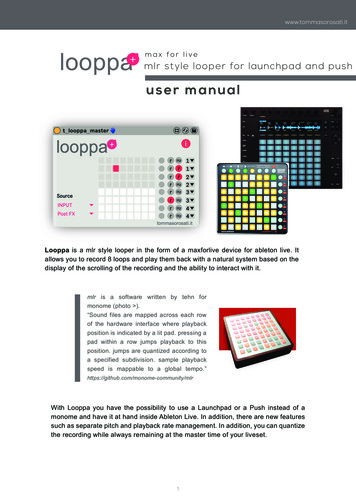
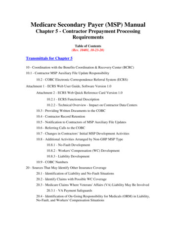
Hardwarewww.ti.com2HardwareThis section describes the F5529 LaunchPad development kit hardware.Figure 7 shows the LaunchPad development kit, with its important features and configuration controls.These controls are described in this section.Develop your own USBapplications and emulate,using a single USB cable!eZ-FET emulator· Open-source· Works with almost anyMSP430 targetIntegrated USB hub andUSB-based power supplyIsolation Jumper Block· Connect to other targets· Allow more accurate powermeasurementRESET button, forthe target deviceButton that invokes theUSB bootstrap loader,for firmware updates40-pin BoosterPack header· Compatible with 20-pin and40-pin BoosterPacks· Now allows BoosterPackswith more functionalityPushbuttons and LEDs,for user interfaceMSP430F5529 USB Microcontroller· 128KB flash, 8KB RAM· Full-speed USB· ADC· 5 timers2· 4 serial interfaces (SPI, UART, I C)· Analog comparator· Much more !Figure 7. EVM Features and ControlsSLAU533D – September 2013 – Revised April 2017Submit Documentation FeedbackMSP430F5529 LaunchPad Development Kit (MSP‑EXP430F5529LP)Copyright 2013–2017, Texas Instruments Incorporated9
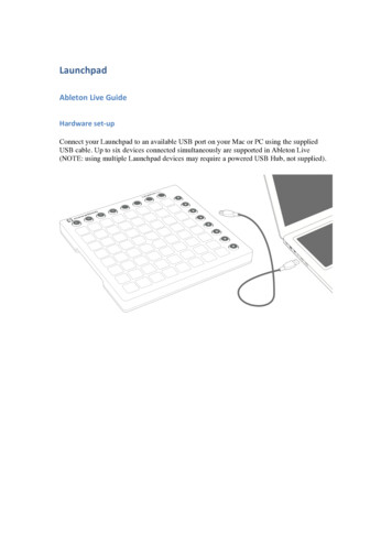
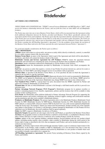
Hardware2.1www.ti.comBlock DiagramFigure 8 shows a functional block diagram of the board.USB Connector5V VBUSTPS622375V-3.3VDC-DC ConvertereZ-FET lite EmulatorESDProtection3.3VUSBUSB Hub / PowerUSB Data6MHzTUSB2046Full-SpeedUSB HubeZ-FET liteEmulatorMCUEmulator USB4MHz5V VBUS32kHz40-pin (4x10) Boosterpack InterfaceSpy-Bi-Wire (SBW)EmulationApplication UART3.3V Power5V VBUS4MHzPowerHeaderJumperTarget DeviceMSP430F5529PowerHeader40-pin (4x10) Boosterpack InterfaceUSB BSL ResetApplication USBIsolationJumper BlockUser LEDs and SwitchesFigure 8. Block Diagram10MSP430F5529 LaunchPad Development Kit (MSP‑EXP430F5529LP)SLAU533D – September 2013 – Revised April 2017Submit Documentation FeedbackCopyright 2013–2017, Texas Instruments Incorporated
Hardwarewww.ti.com2.22.2.1Hardware FeaturesMSP430F5529The MSP430F552x is one of several USB-equipped MSP430 MCU families. It offers: 1.8-V to 3.6-V operation Up to 25-MHz system clock 128KB flash memory, 8KB RAM (in addition to 2KB shared RAM with the USB module) Ultra-low-power operation Full-speed USB with 14 endpoints – enough for almost any USB application Five timers, up to four serial interfaces (SPI, UART, or I2C), 12-bit analog-to-digital converter, analogcomparator, hardware multiplier, DMA, and .0/DPVSSUFigure 9 shows the pinout of the MSP430F5529 in the PN package M NONEP4.6/PM NONEP4.5/PM UCA1RXD/PM UCA1SOMIP4.4/PM UCA1TXD/PM UCA1SIMODVCC2DVSS2P4.3/PM UCB1CLK/PM UCA1STEP4.2/PM UCB1SOMI/PM UCB1SCLP4.1/PM UCB1SIMO/PM UCB1SDAP4.0/PM UCB1STE/PM 9/A13P7.2/CB10/A14P7.3/CB11/A15P5.0/A8/VREF /VeREF P5.1/A9/VREF /VeREF COREFigure 9. MSP430F5529 PinoutSLAU533D – September 2013 – Revised April 2017Submit Documentation FeedbackMSP430F5529 LaunchPad Development Kit (MSP‑EXP430F5529LP)Copyright 2013–2017, Texas Instruments Incorporated11
Hardwarewww.ti.comOther USB-equipped MSP430 MCU families include the smaller F550x family and the larger F563x,F663x, F565x, and F665x families.To compare the various MSP430 MCUs, download the MSP430 Product Brochure, which is also availablefrom http://www.ti.com/msp430. The brochure has a table that lets you see at a glance how the familiescompare and their pricing. This document is frequently updated as new MSP430 MCUs become available.2.2.2eZ-FET lite Onboard EmulatorTo simplify development and keep the user's costs low, TI's LaunchPad development kit developmenttools integrate an emulator for programming and debugging. The F5529 LaunchPad development kit hasthe new eZ-FET lite emulator (see Figure 10).Figure 10. eZ-FET lite EmulatorThe dotted line along the bottom of the image divides the emulator area from the target area. (On theboard, the power and hub area that is shown in Figure 8 is grouped with the emulator.)The eZ-FET lite is simple and low cost. Like the emulator on the G2 LaunchPad development kit (MSPEXP430G2), it provides a "backchannel" UART-over-USB connection with the host, which can be veryuseful during debugging. But unlike the G2 emulator, it: supports almost all MSP430 MCUs has a configurable backchannel UART baudrate is completely open source!The hardware and firmware designs are both available for you to customize. Further details and sourcecan be found on http://processors.wiki.ti.com/index.php/EZ-FET lite.The eZ-FET lite needs a host-side interface. TI provides the "MSP430 DLL", through which PCapplications can access the eZ-FET lite. Such applications include IAR or CCS software environments,MSP430Flasher, Elprotronic's FET-Pro430, mspgcc, and Energia. These solutions generally bundle theDLL.On Windows, the MSP430 DLL is a DLL file, while on Linux it is a *.so file. Like the rest of the eZ-FET litesolution, the DLL is open source.Mac OS X has a limitation that prevents it from enumerating composite USB devices that include a CDCinterface. For this reason, the eZ-FET lite currently does not work with the default OS X.The eZ-FET lite works with almost all MSP430 target devices. If you want to work with a different targetthan the F5529 device on the F5529 LaunchPad development kit, you can disconnect the F5529 using theisolation jumper block and wire your hardware to the emulator through this block.12MSP430F5529 LaunchPad Development Kit (MSP‑EXP430F5529LP)SLAU533D – September 2013 – Revised April 2017Submit Documentation FeedbackCopyright 2013–2017, Texas Instruments Incorporated
Hardwarewww.ti.comFeatures of the eZ-FET lite: USB debugging and programming interface No need to install a driver on the host Windows or Linux PC – it loads silently Application ("backchannel UART") virtual COM port connection with the host, over USB, up to 1 Mbaud LEDs for visual feedback Field-updatable firmware Supports almost all MSP430 MCUsHardware and software requirements PC with Windows or Linux MSP430.DLL 3.3.0.6 or higherThe eZ-FET lite LEDs provide feedback to the user about the emulator status (see Table 2). This behavioris similar to that of the MSP-FET430UIF emulator.Table 2. eZ-FET lite LED Feedback BehaviorGreen LED(Power)Red LED(Mode)OFFOFFeZ-FET lite is not connected to the PC. eZ-FET lite is not ready (for example, after anupdate). Disconnect the LaunchPad development kit from the PC and reconnect it.ONOFFeZ-FET lite is connected and ready, but the. eZ-FET lite interface has not been opened byIDE.ONONeZ-FET lite interface is used by IDE, but no data transfer is taking place.ONBlinkingOFFONAlternating green and red blinking2.2.3DescriptioneZ-FET lite is in action: data transfer between eZ-FET lite and IDE is taking place.A severe ERROR has occurred; disconnect and reconnect the eZ-FET lite. If this does notresolve the error, send for repair.A critical update is running on the eZ-FET lite. Do not interfere with it during this time.Wait until it is finished.Integrated Full-Speed USB HubThe F5529 LaunchPad development kit requires only one USB connection to the host, thanks to anintegrated USB hub (see Figure 11). The emulator and the target device share one USB cable and can beused simultaneously. This simplifies the development setup.USB ConnectorTUSB2046Full-Speed USB HubTargetF5529eZ-FET liteEmulatorFigure 11. Onboard USB Bus PathSLAU533D – September 2013 – Revised April 2017Submit Documentation FeedbackMSP430F5529 LaunchPad Development Kit (MSP‑EXP430F5529LP)Copyright 2013–2017, Texas Instruments Incorporated13
Hardwarewww.ti.comThe eZ-FET lite emulator itself is a composite USB device, which means that it contains two USBinterfaces: A CDC interface (virtual COM port) for the emulation function A CDC interface (virtual COM port) for the application UART(For an explanation of USB interfaces, see the discussion in Step 2 of Section 1.3)These interfaces can be found on the host PC. As an example, Device Manager can be used for thispurpose on a Windows PC. (See Section 3.7 for instructions on starting Device Manager.) Look for theemulator interfaces under the "Ports" section (see Figure 12).Figure 12. F5529 LaunchPad Development Kit USB InterfacesIf you are using a Mac, see Section 2.2.2 for an explanation why these interfaces do not enumerate.Although the MSP Debug Interface virtual COM port is accessible to any host application, do not try tointerface with it; it is only intended for use with supported emulation tools, like CCS and IAR.If you load a USB-equipped software application into the target MSP430F5529 device, then additionalUSB interfaces, defined by that software, will be enumerated on the host.The TUSB2046 is a four-port hub, and two ports are unused. The unused ports are properly terminatedand inaccessible.2.2.4PowerFigure 13 shows the power segment of the block diagram.USB ConnectorDC-DC Converter5V in3.3V outeZ-FET lite 3.3VeZ-FET liteTPS62237eZ-FET lite 5VMSP430F5529 Target5529 Target BoosterPack 3.3V5529 Target BoosterPack 5VIsolationJumper Block* 5V and 3V3Isolation BlockJumpers ControlPower ConnectionMSP430F5529Target DeviceFigure 13. F5529 LaunchPad Development Kit Power Supply14MSP430F5529 LaunchPad Development Kit (MSP‑EXP430F5529LP)SLAU533D – September 2013 – Revised April 2017Submit Documentation FeedbackCopyright 2013–2017, Texas Instruments Incorporated
Hardwarewww.ti.comUSB hosts supply a 5-V power rail to USB devices, called "VBUS". This is convenient for USB devices; ifthey only need to function while attached to a host (for example, mice or keyboards) then they may notneed their own power source. Even if they need to function apart from the USB host and, thus, need theirown power source, being attached to the host places power demands on that device which may not bepresent when the device is not attached; the availability of VBUS can help offset these demands.The F5529 LaunchPad development kit has a high-efficiency dc-dc converter, a TPS62237, that derives anew power rail of 3.3 V from VBUS. This 3.3-V rail sources the eZ-FET lite, hub, target F5529 device, andthe 3.3-V pin on the BoosterPack plug-in module header.VBUS is still made available to the target F5529 device for two reasons. One reason is that the presenceof VBUS is how a USB device determines the presence of a USB host. The other reason is that VBUSalso supplies power to the target F5529 USB module.USB-equipped MSP430 MCUs have an integrated 5-V to 3.3-V LDO. On the F5529 LaunchPaddevelopment kit, this LDO is only used for the MSP430F5529 USB operation. However, the integratedLDO also has an output pin that can source a modest amount of power to external circuitry. See thedevice data sheet for more details. Sometimes, this output pin can eliminate the need for external powermanagement. But because the current limit may be too low for some applications, the F5529 L
24 Browse to Demo Project for Import Function . Custom USB functionality can be quickly added using the free open-source USB tools and examples available in the MSP430 USB Developers Package. This includes the MSP430 USB Descriptor Tool, . If you later download the software demo (or any software) to the F5529