Transcription
EDJanuary 2, 2018-DRAINAGE
CITY OF STEPHENVILLEENGINEERING STANDARDS MANUAL
CITY OF STEPHENVILLEENGINEERING STANDARDS MANUALTABLE OF CONTENTSPART I GENERAL . 11.11.21.31.41.51.61.71.81.9PURPOSE .2AUTHORIZATION.2SCOPE .2STANDARD CONSTRUCTION DETAILS .2CORRELATION OF MANUAL AND STANDARD CONSTRUCTION DETAILS .2UTILITY ASSIGNMENTS .3GENERAL NOTES .3CORRELATION OF MANUAL AND SUBDIVISION ORDINANCE .3VARIANCE PROCEDURE .3PART II WATER AND SEWER . 41. WATER MAINS .51.1.1.2.1.3.1.4.1.5.1.6.1.7.1.8.1.9.1.10.GENERAL . 5WATER LINE MATERIAL. 5LOCATION . 6WATER VALVES . 6FIRE HYDRYANTS . 5FIRE LINE METERING . 8WATER LINE MATERIAL. 8MINIMUM COVER . 8CLEARANCES BETWEEN WATER AND WASTEWATER LINES . 8SERVICE CONNECTIONS . 82. WASTEWATER .92.1.2.2.2.3.2.4.2.5.2.6.2.7.MINIMUM SIZE . 9LOCATION . 9MINIMUM COVER . 9WASTEWATER FLOWS, SIZE AND GRADES . 9MANHOLES . 9LATERALS . 9WASTEWATER LINE MATERIALS . 93. UTILITY EASEMENTS .123.1.3.2.REQUIREMENTS . 12LANDSCAPING IN UTILITY EASEMENTS . 12i
PART III STREETS . 131. STREET FUNCTIONAL CLASSIFICATIONS .141.1. GENERAL . 142. STREET DIMENSIONS .142.1.2.2.2.3.2.4.2.5.2.6.2.7.2.8.GENERAL . 14DESIGN VEHICLES . 15DESIGN SPEED . 17HORIZONTAL GEOMETRICS . 17VERTICAL ALIGNMENT . 19SIGHT DISTANCE AT INTERSECTIONS . 22MEDIAN OPENINGS . 24CUL-DE-SACS . 243. DRIVEWAY STANDARDS .243.1.DRIVEWAY REQUIREMENTS . 244. TRAFFIC IMPACT ANALYSIS GUIDELINES 274.14.24.34.44.54.6DEFINITIONS – THE FOLLOWING TERMS ARE USED IN THIS ARTICLE . 27PURPOSE . 27APPLICABILITY . 27WHEN TRAFFIC IMPACT ANALYSIS (TIA) IS REQUIRED . 27ROLES OF APPLICANT AND CITY . 28TRAFFIC IMPACT ANALYSIS (TIA) REQUIREMENTS . 285. PAVEMENT DESIGN .315.15.25.35.4STANDARD STREET AND ARTERIAL PAVEMENT DESIGN . 31GEOTECHNICAL INVESTIGATION REQUIRED . 31GUIDELINES FOR STAB. OF SUBGRADE SOILS CONTAININGSULFATES . 31ALTERNATE PAVEMENT DESIGN . 32ii
6. PERMANENT LANE MARKINGS .336.1PAVEMENT MARKINGS PLAN . 337. LANDSCAPING IN PUBLIC RIGHT-OF-WAY .337.17.27.37.47.5GENERAL. . 33METERING . 33OTHER REQUIREMENTS . 33PLAN SUBMITTAL REQUIREMENTS . 34OWNERSHIP AND MAINTENANCE . 348. STREET LIGHT REQUIREMENTS .358.18.28.38.48.5GENERAL. 35STREET LIGHT REQUIREMENTS BY STREET CLASSIFICATION 35STREET LIGHT LOCATIONS . 35PLAN SUBMITTAL REQUIREMENTS . 35COSTS . 359. TEXAS ACCESSIBILITY STANDARDS (TAS) .369.1GENERAL. 36PART IV DRAINAGE . 371. INTRODUCTION .381.11.21.31.41.5PURPOSE . 38RELATIONSHIP OF CITY OF STEPHENVILLE MANUAL TO REGIONALINTEGRATED STORMWATER MANAGEMENT CRITERIAL MANUAL FORSITE DEVELOPMENT AND CONSTRUCTION . 38NOTES AND ABBREVIATIONS . 38CONTACT INFORMATION . 38REFERENCES . 392. GOALS AND OBJECTIVES OF THE STEPHENVILLE STORMWATER MANAGEMENTPROGRAM .393. CITY OF STEPHENVILLE STORMWATER POLICY STATEMENTS .40iii
TABLESNo table of contents entries found.Table II-1Minimum Manhole Sizes . 11Table III-1Street Classifications and Dimensions .15Table III-2Intersection Design Standards . 16Table III-3Minimum Centerline Radius for Roadways . 18Table III-4Maximum Street Grades . 20Table III-5Minimum Length of Vertical Curve. 21Table III-6Sight Distance Requirements . 22Table III-7Driveway Requirements . 25Table III-8Minimum Driveway Storage Length (L).26Table III-9Standard Street and Thoroughfare Pavement Thickness . 26FIGURESFigure II-1Figure III-1Figure III-2Figure III-3Figure III-4Peak Wastewater Flow Rates . 10Intersection Design Diagram . 16Sight Distance Requirements . 23Visibility Triangles . 23Driveway Requirements . 26APPENDICESAppendix A Utility AssignmentsAppendix B General Notes for Construction PlansAppendix C integrated Stormwater Management (iSWM) Criteria Manual for Site Developmentand Constructioniv
ENGINEERING STANDARDS MANUALPART I - GENERAL1
CITY OF STEPHENVILLEENGINEERING STANDARDS MANUALPART I - GENERAL1.1PURPOSEThe purpose of the Engineering Standards Manual (ESM) is to provide a set of guidelines fordesigning water, sewer, streets and drainage facilities and other public improvements and forpreparing construction plans for such facilities which are to be owned, operated and/or maintainedby the City of Stephenville, Texas. These guidelines shall be used by the City, Consulting Engineersfor both public and private developments in the City of Stephenville and its extra-territorial jurisdiction(ETJ) as well as for plat approval, and the issuance of building and earthwork / grading permits,approval of construction plans by the City, site plan approval, and for other construction within publicrights-of-way and easements subject to Section 245 of the Texas Local Government Code. Thedesign criteria and may be modified by administrative action and subsequent City Ordinance at suchtimes as may be appropriate. The standard construction details may be modified by administrativeaction in keeping with the most up-to-date construction materials and techniques. All water, sewer,street and drainage installations shall be in accordance with the City Standards and Specificationsand all projects shall meet state and federal requirements.1.2AUTHORIZATIONThe Standards shall be in full force and effective immediately upon adoption by the City Council.Projects will be required to comply with all requirements. The standards include the various designcriteria defined in this ESM, Standard Construction Details, technical specifications, the currentversions of the North Central Texas Council of Governments (NCTCOG) Specifications for PublicWorks Construction, as amended from time to time and the City’s supplements to the NCTCOGspecifications which are considered minimum requirements for the design and construction ofadequate public facilities within the City. The Engineer of record shall bear the sole responsibilityfor meeting the Engineering Standard of Care for all aspects of the design and providing a designthat’s required by the site-specific conditions and intended use of the facilities, while at a minimummeeting the City’s design and construction requirements.1.3SCOPEThe scope of this section of the Engineering Standards Manual includes the various designelements, criteria, standards and instructions required for the design of streets and arterials,drainage facilities, water lines, wastewater lines, and other public improvements.1.4STANDARD CONSTRUCTION DETAILSIn addition to the guidelines contained in this manual, the City maintains drawings entitled"STANDARD CONSTRUCTION DETAILS", which are to be used in conjunction with this DesignManual in the preparation of engineering plans.1.5CORRELATION OF MANUAL AND STANDARD CONSTRUCTION DETAILSThe Engineering Standards Manual and Standard Construction Details are complementary andwhat is called for by one shall be binding as if called for by both.In case of conflict between the Engineering Standards Manual and Standard Construction Details,the City reserves the right to make the interpretation that is in the best interest of the City.2
1.6UTILITY ASSIGNMENTSUtilities are to be located in public rights-of-way in the location shown in Appendix "A". The Cityshall determine the location of utilities where special circumstances prevent the standard utilityassignments from being used.1.7GENERAL NOTESAll construction plans for the projects described above shall contain the applicable general noteslisted in Appendix "B".1.8CORRELATION OF MANUAL AND SUBDIVISION ORDINANCEThe Engineering Standards Manual (ESM) and the Subdivision Ordinance are complementary andwhat is called for by one shall be binding as if called for by both.In case of conflict between the ESM and the Subdivision Ordinance the more stringent criteria shalltake precedence.1.9VARIANCE PROCEDUREThe City of Stephenville City Administrator will consider variance requests on an individual basiswhen, due to geographic or topographic limitations of the site on which the facilities are to beconstructed, there are circumstances which warrant an individual design. In considering whether ornot a variance should be granted, the City Administrator shall consider the following factors:a. The extent to which the proposed design meets the spirit and intent of this Ordinance throughthe use of materials, design criteria and engineering which will protect the health, safety andgeneral welfare of the public; andb. The extent to which the proposed design meets the spirit and intent of this Ordinance throughthe use of materials, design criteria and engineering which will protect the health, safety andgeneral welfare of the public; andc. The positive or negative impact of the proposed design on surrounding property uses andproperty values, in comparison to the expected impact of the facilities if same were built instrict conformity with the standards of this Ordinance; andd. The extent to which the proposed design accomplishes the purposes of the City’s EngineeringStandards Manual and Standard Construction Details.A variance shall not be granted to serve as a convenience to the applicant or for reasons relatedto economic hardship.3
CITY OF STEPHENVILLEENGINEERING STANDARDS MANUALPART II – WATER AND SEWER4
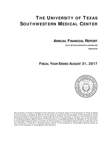
CITY OF STEPHENVILLEENGINEERING STANDARDS MANUALPART II - WATER AND SEWER LINESIWATER MAINS1.1GENERALWater mains shall generally be placed on the north and east sides of a street, in accordance withthe utility assignments in Appendix A. Where applicable, line sizes shall comply with the City'sWater Master Plan or subsequent revisions.a.1.2Water lines in the City of Stephenville are categorized as:1.Distribution Lines – sizes 12-inch and less.2.Transmission Mains – sizes greater than 12-inches.b.Lines shall be minimum 6-inch diameter pipe in residential neighborhoods. A minimum8-inch diameter pipe shall be used in commercial and industrial districts and shall be aminimum of 12-inch diameter pipe if the line is over 600 feet in length.c.Dead end lines shall not be allowed.d.Fire hydrant lead lines shall be 6-inch diameter pipe and no greater than 50 feet in length.Any fire hydrant lead line over 20 feet may be required to be 8-inch diameter pipe.e.Water lines shall be shown with a profile view, on plan sheets, to confirm separationdistances from other utility lines. Stationing and elevations to 0.01 feet shall be providedfor all water lines.WATER LINE MATERIALa.Water mains 24-inches in diameter and smaller shall be AWWA C900-07 Class 235 (DR18) PVC, mechanical joint, or a bell and spigot joint unless otherwise approved by theCity. A recession in the bell shall have a single rubber gasket. Ductile iron fittings withpolywrap shall be used unless otherwise approved by the City.b.Water mains greater than 24 inches in diameter and larger shall generally be Ductile IronPipe, (DIP) complying with AWWA C151, with bituminous coating outside and mortarlining inside in accordance with AWWA C104. Mechanical joint fittings shall be used andshall conform to ASTM C111. The minimum Pressure Class shall be 150 psi. All pipe andfittings shall be encased in polyethylene in conformance with ASTM C105.c.Water lines shall be minimum pressure Class 150.d.Water mains shall be standard sizes that are readily available, such as 6-inch 8-inch,12-inch, 16-inch, 18-inch, 20-inch, 24-inch, 30-inch, and 36-inch.5
1.3LOCATIONWater mains shall be constructed with extensions to the development boundary to allow for directconnection by future developments. Water mains shall generally be located in accordance withUtility Location Requirements for the City of Stephenville. See Appendix ”A”.1.4WATER VALVESValves, 16-inch diameter and smaller, shall be placed on or near street property lines and shall bespaced at a maximum of 800 feet apart in residential areas and 500 feet in all other districts andshall be placed in such a manner as to require, preferably two, but not more than three valves toshut down each City block, or as may be required to prevent shutting off more than one fire hydrant.On cross-feed mains without services, a maximum of four valves shall be used to shut down eachblock. Also, valves shall be placed at or near the ends of mains in such manner that a shut-downcan be made for a future main extension without causing loss of service on the existing main. Thelocation of valves larger than 16-inches will be as approved by the Director of Public Works. Valves16-inches and smaller shall be Resilient Seat Gate Valves (RSGV). Restrained joints shall be usedin all installations. All valves will be gate valves, unless otherwise approved by the City and shallbe manufactured by one of the following companies: American, Mueller or City-approved equal.1.5FIRE HYDRANTSa.Number and LocationsA sufficient number of fire hydrants shall be installed to provide hose stream protection forevery point on the exterior wall of the building. There shall be sufficient hydrants toconcentrate the required fire flow, as recommended by the publication "GUIDE FORDETERMINATION OF REQUIRED FIRE FLOW" published by the Insurance ServiceOffice, as required by the adopted version of the International Fire Code by the City ofStephenville, or as approved by the Fire Marshal, around any building with an adequateflow available from the water system to meet this required flow. Fire hydrant markers shallbe provided at each hydrant. In addition, the following guidelines shall be met or exceeded:1.SINGLE FAMILY AND DUPLEX RESIDENTIAL - As the property is developed, firehydrants shall be located at all intersecting streets and at intermediate locationsbetween intersections at a maximum spacing of 500 feet between fire hydrants asmeasured along the route that fire hose is laid by a fire vehicle. All buildings shallbe within a 500 foot radius of a fire hydrant.2.MULTIFAMILY RESIDENTIAL - As the property is developed, fire hydrants shall belocated at all intersecting streets and at intermediate locations between intersectionsat a maximum spacing of 400 feet as measured along the length of the center lineof the roadway, and the front of any structure at grade and shall be no further than400 feet from a minimum of two fire hydrants as measured along the route that a firehose is laid by a fire vehicle. All buildings shall be within a 400 foot radius of a firehydrant.3.OTHER DISTRICTS - As the property is developed, fire hydrants shall be located atall intersecting streets and at intermediate locations between intersections at amaximum spacing of 300 feet as measured along the length of the center line of theroadway, and the front of any structure at grade and shall be no further than 400feet from a minimum of two fire hydrants as measured along the route that a fire hoseis laid by a fire vehicle. All buildings shall be within a 300 foot radius of a fire hydrant.6
4.PROTECTED PROPERTIES - Fire hydrants required providing a supplemental watersupply for automatic fire protection systems shall be within 100 feet of the fire departmentconnection for such system.5.Fire hydrants shall be installed along all fire lane areas as follows:(a)(b)b.Non-Residential Property or Use(1).Within 150 feet of the main entrance.(2).Within 100 feet of any fire department connection.(3).At a maximum intermediate spacing of 300 feet as measured along thelength of the fire lane.Apartment, Townhouse, or Cluster Residential Property or Use(1).Within 100 feet of any fire department connection.(2).At maximum intermediate spacing of 400 feet as measured along thelength of the fire lane.6.Generally, no fire hydrant shall be located closer than fifty (50) feet to a non-residentialbuilding or structure unless approved by the City.7.In instances where access between the fire hydrant and the building that the hydrant isintended to serve may be blocked, extra fire hydrants shall be provided to improve thefire protection. Railroads, expressways, major thoroughfares and other man-made ornatural obstacles are considered as barriers.8.Along divided roadways, fire hydrants shall be installed on both sides of the roadway soas to preclude the need for laying hose across the roadway.Restrictions1.All public fire hydrants shall be the type indicated on the approved plans and shall beplaced on water mains of no less than six inches (6") in diameter. Fire hydrants shall bemanufactured by one of the following companies and meet the City’s standard; EastJordan, Mueller, or City-approved equal.2.Gate valves shall be placed on all fire hydrant leads.3.Required fire hydrants shall be installed so the breakaway point will be no less than three(3") inches, and no greater than five (5") inches above the grade surface.4.Fire hydrants shall be located a minimum of two (2') feet and a maximum of six (6') feetbehind the curb line, depending on the location of the sidewalk. The fire hydrant shall notbe located in the sidewalk.5.All required fire hydrants placed on private property shall be adequately protected byeither curb stops or concrete filled steel posts or other methods as approved by the Cityand shall be in easements. Installation and maintenance of stops or posts shall be theresponsibility of the landowner on whose property said private fire hydrant is placed.6.All required fire hydrants shall be installed so that the steamer connection will face thefire lane or street, or as directed by the City.7
1.67.Fire hydrants, when placed at intersections or access drives to parking lots, whenpractical, shall be placed so that no part of the fire truck will block the intersection orparking lot access when connections are made to the fire hydrant.8.Fire hydrants, required by this article, and located on private property, shall be accessibleto the Fire Department at all times.9.Fire hydrants shall be located at street or fire lane intersections, when feasible.10.Fire hydrant barrels shall arrive at the job site after being painted by the manufacturer enameledin Silver. Bonnets shall be painted according to Standard Details.FIRE LINE METERINGThe City of Stephenville will own and maintain all public fire lines serving public fire hydrants.Sprinkler service lines, fire line connections and other fire lines which are not maintained by the Cityshall be equipped with either a City-approved water meter or a detector check assembly having acapacity equal to the required fire flow. Water meters and detector check assemblies shall beconstructed in accordance with City standards.1.7MINIMUM COVERThe minimum cover to the top of the pipe must vary with the valve stem. In general, the minimumcover below the street grade should be as follows: 12-inch and smaller, 3.0 feet. Lines larger than12-inches shall have 4.0 to 6.0 feet of cover. Water lines with more than 6.0 feet of cover shall beapproved by the City.1.8CLEARANCES BETWEEN WATER AND WASTEWATER LINES:Clearances between water and wastewater lines shall meet TCEQ requirements. The minimumclearances for water and wastewater lines crossing storm drains shall be two (2) feet or one-half (0.5)feet when the water or wastewater line is encased per City standards.1.9METER BOX AND SERVICEA water service with a meter box is constructed from the main to a point just behind the curb line,usually in advance of paving. The location of the meter box is generally as shown on the UtilityAssignments detail sheets and as shown on the City of Stephenville Details. On multiple apartmentsand business properties, the desired size and location is usually specified by the owners. Minimumrequirements for water service sizes are:1.10a.¾ or one-inch min. single water services are required to serve all single-family residential lots.b.Each residence shall have dedicated meter and service line on single-family residential lots.c.The size of apartment, condominium, or multi-family services will depend on the number ofunits served with a minimum of one meter per building.SERVICE CONNECTIONSa.Service shall generally not be connected to fire hydrant leads unless approved by the City.b.Service connections shall not be allowed to transmission mains.8
II.2.1WASTEWATERMINIMUM SIZEThe minimum size of wastewater mains in the City of Stephenville shall be 8-inch diameter. 6-inchlines may be used to connect to existing 6-inch mains subject to City approval. Line sizes shallconvey peak flows as shown on the City’s Wastewater Master Plan or subsequent revisions. Allwastewater lines shall be one of the following standard sizes such as 8-inch, 10-inch, 12-inch,15-inch, 18-inch, 21-inch, 24-inch, 30-inch, and 36-inch.2.2LOCATIONWastewater mains shall generally be placed on the south and west sides of a street, in accordancewith the utility assignments in Appendix A. Where applicable, line sizes shall comply with the City'sWastewater Master Plan or subsequent revisions.1.2.3For Planned Developments, ALL necessary sanitary sewer services must be constructed upto the right-of-way. In areas outside of Planned Developments, sanitary sewer stub outsmust be provided to allow future developments to connect service lines.MINIMUM COVERMinimum cover over all wastewater mains shall be a minimum of 2.0 feet unless approved by theCity. Approved mains with less than 3.0 feet of cover may be required to be capped as per the“Cap Detail” on the Wastewater Standard Details. See City Standard Details.2.4WASTEWATER FLOWS, SIZE AND GRADESWastewater lines shall be designed to convey flows from all upstream areas based on ultimatedevelopment of the sewershed basin. Wastewater main sizes shall be obtained from the City’sWastewater Master Plan. Subbasin flow shall be computed in accordance with the followingformula:Q C0.89295Where:Q Peak wastewater flow (million gallons per day)C Equivalent single family connectionsThis equation is graphically displayed in Figure II-1. Equivalent single family connections arebased on a density of 3.1 persons per dwelling unit. Densitie
Water lines in the City of Stephenville are categorized as: 1. Distribution Lines - sizes 12-inch and less. 2. Transmission Mains - sizes greater than 12-inches. b. Lines shall be minimum 6-inch diameter pipe in residential neighborhoods. A minimum