Transcription
ACC Series ChillersProduct Catalog
Jetsonwww.JetsonHVAC.comContentsFeatures and Benefits . 5Application Information. 10Model Number Description . 19Digits 4 — Chiller Type . 21Digits 5 to 7 — Nominal Capacity . 21Digit 8 — Unit Voltage. 21Digit 9 — Unit Application . 22Digit 10 — Steps of Capacity . 22Digit 11 — Refrigerant Type . 22Digit 12 — Efficiency . 23Digit 13 — Design Sequence . 23Digit 14 — Evaporator Heat Exchanger Type . 23Digit 15 — Evaporator Temperature Range . 23Digit 16 — Evaporator Flow and Valves . 24Digit 17 — Condenser Heat Exchanger Type . 24Digit 18 — Condenser Fan Control . 24Digit 19 — Condenser Heat Recovery . 25Digit 20 — Condenser Heat Recover Control Valves . 25Digit 21 — Power Connection . 26Digit 22 — Power Feed . 26Digit 23 — Service Options . 27Digit 24 — Control Style . 28Digit 25 — Local Unit Controller Interface . 28Digit 26 — Remote BMS Interface (Digital Comm). 28Digit 27 — Blank . 29Digit 28 — Refrigeration Options . 29Digit 29 — Refrigeration Accessories . 29Digit 30 — Water Connection . 30Digit 31 — Water Side Pressure . 30Digit 32 — Water Strainer(s) . 31Digit 33 — Water Accessories . 31Digit 34 — Free Cooling . 31Digit 35 — Sound Attenuator . 323
Jetsonwww.JetsonHVAC.comDigit 36 — Guards. 32Digit 37 — Exterior Finish and Shipping Splits . 32Digit 38 — Warranty . 32Digit 39 — Special Options . 33General Data . 34Performance Correction Factors . 37Electrical Service Sizing Data . 38Weights and Dimensions . 40Literature Change History . 484
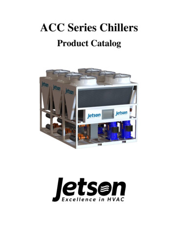
Jetsonwww.JetsonHVAC.comFeatures and BenefitsFlexibility of DesignWith model sizes ranging from 10 to 80 tonsand configurable into arrays up toapproximately 800 tons the ACC Series chillercan suit many applications. The installation ofsmall chillers as needed is both moreeconomically practical and energy efficientthan a single large centralized chilled waterplant, especially at part load and in applicationwhere chiller uptime and redundancy areimportant. For new installations or buildingrenovations, the ACC Series easily allowslarge tonnage systems to be built with multiplesmaller modules.Because the ACC Series can be applied as anindividual chiller or applied as a high capacitymulti-stage, multi-chiller array by using theoptional array controller package, the ACCSeries chillers can be configured to meetcapacity needs ranging from 10 tons to over800 tons.ConvenienceThe ACC Series chiller was designed withconvenient installation and servicing in mind.The ACC Series chiller is delivered to thejobsite ready for installation and startup. Jetsonoffers a wide variety of standard and optionalfeatures, including single or dual circuitrefrigeration systems and shell and tube orbrazed plate evaporators. All of thesecomponents are piped, wired, and run testedbefore they are shipped from the factory. Allmodels feature lockable, hinged access doorsto the electrical components. Waterconnections are conveniently located tominimize the equipment’s installed footprintand provide clear access to heat exchangers,filter driers and thermal expansions valves.Customer connections are 6-inch grooved pipeand arrive ready for immediate connection tothe customer supply/return lines and, ifapplicable, to other adjacent ACC Seriesmodular chillers.ReliabilityThe active freeze protection system on ACCchillers continuously monitors the suctiontemperature to prevent evaporator operation infreezing conditions. When suction pressureapproaches freezing conditions the activefreeze protection reacts to warm theevaporator. If the active freeze protectionsystem can prevent a freezing condition thechiller will continue normal operation. If afreeze condition is imminent, the machine willlock out and provide an alarm. This systemhelps enhance the longevity of chilleroperation and is included on all Jetson chillers.Core temperature sensors are installed in everyACC brazed-plate evaporator as a redundantlow water temperature safety.Jetson integrates the latest in scroll compressortechnology into all of its products for improvedoperational reliability. Each chiller is factoryinspected and checked for leaks before leavingthe factory. Current transducer continuouslymonitors compressor amp draw and stopoperation if excessive amps occur.Every ACC modular chiller is run test beforeshipment, minimizing startup delay. A data logis retained at the factory for each unit shipped.Quiet OperationIn addition to being dependable, the hermeticscroll compressors included in each ACCSeries chiller offer quieter operation thancomparable reciprocating compressors. Eachcompressor is placed on rubber isolator tominimize vibration. ACC Series chillers areavailable with compressor blankets and/or asound enclosure. Sound enclosures fullyenclose the compressors with sounddampening material to provide enhanced5
Jetsonwww.JetsonHVAC.comsound reduction compared to sound blankets ornon-isolated compressors.EfficiencyThe use of scroll compressors, while beingboth reliable and quiet, also boasts reducedfrictional losses and improved efficiency overcomparable reciprocating compressors. TheACC Series chiller maintains control on theleaving water temperature by cyclingcompressors on and off at part load conditions,maintaining efficient operation across theentire range of operation. All ACC Serieschillers meet or exceed ASHRAE 90.1 – 2019.ServiceabilityStandard, integral valving makes it possible toisolate the ACC heat exchangers for routinemaintenance. Once isolated, water-torefrigerant heat exchangers have inlet andoutlet grooved pipe connections readilyaccessible to allow for backflushing, chemicalcleaning without having to remove theexchanger.Smart ControlsEvery model is furnished with amicroprocessor controller that cycles thecompressors to maintain the leaving watertemperature over a wide range of operatingconditions. A convenient alphanumeric LCDdisplay that is updated once per second. Inputsare made using large function keys with menudriven prompts. Schedules are available with aseven-day built-in time clock. Terminals areprovided for remote stop-start and for remotereset of the leaving water temperature setpoint.The controller features 12 analog and 4 digitalinputs as well as 4 analog outputs. Nonvolatilememory is used for all control functions.Additional optional features include diagnosticsensors for pressure and temperature on eachrefrigerant circuit, current sensors for eachcompressor, and a RS-485 port allowingcommunication with other manufacturer’scontrol systems.6Figure 1 -Keypad Controller DisplayBuilding CommunicationsWhen the ACC Series chiller is used inconjunction with a building managementsystem (BMS), the chiller can be monitoredand given input from a remote location. Thechiller can be set up to fit into the overallbuilding control strategy by using remoterun/stop input, remote demand limit resetand/or remote chilled water reset functions.As standard, the unit controller Ethernet port isalways ready to talk BACnet IP andModbus TCP/IP (Modbus RTU uses theRS485 network port). BACnet MS/TP,Johnson N2 and LonTalk are optionalprotocols that can be factory-installed. The unitcontroller can facilitate hundreds of controlpoints, including the following popular BMScommunications: Remote Off/Auto signal (input from BMS) Demand Limit Reset signal (input fromBMS) Chilled Water Temperature Reset signal(input from BMS) Customer Alarm relay (view only) Chiller Run Indication (view only) Entering Chilled Water Temperature (viewonly)
Jetsonwww.JetsonHVAC.com Leaving Chilled Water Temperature (viewonly)Chilled Water Flow Switch input (viewonly)Condenser Pump relay (view only)Chilled Water Pump relay (view only)System ProtectionA complete safety lockout system with alarmsprotects the ACC Series chiller operation topotentially avoid compressor and evaporatorfailures. The unit controller directly sensespressures, temperatures, amperage, motorfaults, etc. All control variables that govern theoperation of the chiller are evaluated everysecond for exact control and protection. Thefollowing is an abbreviated list of safeties thatare incorporated into the standard chilleralgorithm control. No Flow Protection – To protect thechiller from no water flow to theevaporator, the chiller is enabled to runonly if the required flow proving deviceindicates there is flow present. If the chilleris active and flow is lost; the chiller willlock out and an alarm is generated. Low Suction Pressure – To protect thecompressors and evaporator, if therefrigerant suction pressure drops belowthe set point value for a specified period oftime, a safety trip occurs. This safety isbypassed when the compressor is in aPump Down state. Unsafe Suction Pressure – To protect thecompressors and evaporator, if therefrigerant suction pressure drops belowthe set point value for a specified period oftime, the chiller will immediately lock out,and an alarm is generated. Heat Exchanger Freeze Protection – Toprotect the evaporator from low watertemperatures,thechilledwatertemperature is monitored inside the core ofthe evaporator and leaving the evaporator.If these temperatures fall below their setpoint temperatures for the set period oftime, the entire system will lock out and analarm is generated. Active Freeze Protection System –Working in conjunction with the lowsuction pressure and freeze protectionsafeties to avoid nuisance safety trips, theactive freeze protection valve is openedwhen the suction pressure goes below thelower set point value and warms theevaporator until the freeze conditions areabated. The valve will stay open until thesuction pressure rises safely above theupper set point level. High and Low Discharge Pressure, Highand Low Superheat, High and LowCompressor Amps – The compressorswill be locked out if any one of thesecontrol variables rises above the upper setpoint value or falls below the lower setpoint value for the set amount of time foreach, and an alarm is generated. Optional Phase/Power Monitor – Thefactory-installed phase/power monitorcontinuously monitors the incoming powersupply to the chiller for low voltage, phaserotation reversal, loss of phase and phaseimbalance. Should one of these parametersbe incorrect, the phase/power monitorrelay will lock out (de-energize) and thefault LED on the monitor will blink. Theunit controller will indicate the lockout,and an alarm is generated.As an additional layer of system protection,mechanical high- and low-pressure switchesare used in conjunction with the refrigerantcircuit high- and low-pressure transducers andunit controller.7
Jetsonwww.JetsonHVAC.comStandard Peripheral Control FeaturesThe following peripheral control features andprogram logic come standard on all ACCSeries chillers. Designated terminals on thefield connection terminal strip in the controlpanel are provided for field connection of: Remote Off/Auto (dry contact closurefrom a remote device - input) Required Chilled Water Flow ProvingDevice (dry contact closure from a remotedevice - input) Remote Alarm (dry contact closure to aremote device - output) Required Chilled Water Pump Enable(dry contact closure for 1 chilled waterpump - output) Condenser Water Pump Enable (drycontact closure for 1 condenser waterpump - output)Standard Capacity ControlStandard capacity control on the ACC Serieschillers is accomplished by staging the scrollcompressors on and off. The unit controllerwill maintain a set point leaving chilled watertemperature within a control zone usingproportional, integral derivative (PID) logic. Ifthe leaving chilled water temperature starts todecrease and falls below the set point, the unitcontroller will turn one stage off. A furtherreduction in temperature will result in a secondstage being turned off. The reverse is true asthe leaving chilled water temperatureincreases. Lead/lag logic is used to even therun time on the individual compressors.Optional Capacity ControlChilled water temperature reset can beaccomplished in two ways. In buildings with abuilding management system, the ACC Seriesunit controller allows the BMS tocommunicate an offset to the chilled watertemperature set point. If a BMS is not beingused, the unit controller can accept a fieldprovided 0 to 5 VDC analog input signal. Asthe input voltage varies away from center8(2.5V), the chilled water temperature set pointwill be offset proportionally.Note: This control logic is factory-installedand must be denoted at the time of ordering.Demand limiting is a form of capacity controlthat limits the number of capacity steps thecompact chiller is allowed to operate. It can beaccomplished in the same two ways as thechilled water temperature reset: through BMSor field-provided 0 to 5 VDC input signal.Note: This control logic is factory-installedand must be denoted at the time of ordering.Array ControlThe array controller option allows the ACCSeries chiller to be an ideal solution forfacilities with growing occupancy andstructural expansion plans because chillers canbe added as capacity needs increase orapplications where convenient redundancy isneeded.ACC Series air-cooled chiller arrays can becontrolled by two different array controllerconfigurations, depending on the needs of theapplication. Both options allow the array to becontrolled and operated like a single, highercapacity, multistage chiller. Capacitymodulation and equalization of compressor runtime is managed by the array controller. Thearray controller uses the same standardcapacity control logic as an individual ACCunit controller but with more stages ofcapacity.Supervisory Array ControllerThis option allows up to ten (10) ACC Serieschillers to be controlled and operated. TheSupervisory Array Controller requires eachmodule have an individual unit controller. Thisoption is beneficial in applications requiringseven (7) or more modules to be controlled andin applications where chiller uptime is critical.
Jetsonwww.JetsonHVAC.comPower (115VAC) must be provided to a circuitbreaker inside the Supervisory ArrayController enclosure panel to power theSupervisoryArrayController.TheSupervisory Array Controller enclosure alsocontains a field connection terminal strip anddoor-mounted off/auto switch, run indicatorlight and alarm indicator light.The Supervisory Array Controller is accessedin the same manner as the unit controller,through the keypad display or PC/laptop. Ifcommunication between the individual ACCSeries chiller unit controller(s) and theSupervisory Array Controller is lost, or theSupervisory Array Controller fails, theindividual ACC Series chillers can be shiftedinto manual mode to operate independent fromthe Supervisory Array Controller and willmaintain a “manual mode” default chilledleaving water temperature set point.N 1 logic can be utilized with the SupervisoryArray Controller when each chiller in an arrayis equipped with optional chilled watermotorized on-off valve, optional condenserwater regulating valve and a standby chiller isinstalled in the array.replaced by modular chillers controlled withone controller. The Master-Slave ArrayController is also applicable for chillerapplications that do not require redundantoperation and first cost is considered animportant factor.The Master-Slave Array Controller is poweredfrom the unit supply power and factoryprovided transformer or low voltage powersupply. The Master-Slave array control panelalso contains a field connection terminal stripand door-mounted off/auto switch, runindicator light and alarm indicator light.The Master-Slave Array Controller is accessedthrough the keypad display, touchscreendisplay or PC/laptop. If communicationbetween the individual ACC Series chillermodules and the Master-Slave ArrayController is lost, that module will beinoperable until communication to the moduleis restored. The Master-Slave Controller willcontinue to control the other modules in thearray. If Master-Slave Array Controller fails,the array will be down until the controller isrepaired or replaced.N 1 logic can be utilized with the MasterSlave Array Controller, via the demand limitfunction, when each chiller in an array isequipped with optional chilled watermotorized on-off valve, optional condenserwater regulating valve and a standby chiller isinstalled in the array.Figure 2 - Supervisor Controller LayoutMaster-Slave Array ControllerThis option allows up to six (6) ACC Serieschillers to be controlled and operated. TheMaster-Slave Array Controller requires only asingle controller for the array. This option isbeneficial in replacement applications where asingle larger chiller, with one controller, isFigure 3 - Master-Slave Controller Layout9
Jetsonwww.JetsonHVAC.comApplication InformationUnit SizingSee JESS (Jetson Engineering SelectionSoftware) for unit capacities. Intentionallyover-sizing a unit to assure adequate capacityis not recommended. Erratic system operationand excessive compressor cycling are often adirect result of an oversized chiller. In addition,an oversized unit is usually more expensive topurchase, install, and operate. If oversizing isdesired consider using two smaller units.Altitude EffectAt elevations substantially above sea level, thedecreased air density will decrease condensercapacity and, therefore, unit capacity andefficiency.Evaporator Design DataThe system can start and pull down with up to90 F entering fluid temperature. Forcontinuous operation, it is recommended thatthe entering fluid temperature not exceed 75 F.The maximum sustained leaving chilled-fluidtemperature is 65 F. The chiller with standardevaporator must not be operated with a leavingwater temperature of less than 42 F for a plainwater application. The chiller with highcapacity evaporator must not be operated witha leaving water temperature of less than 40 Ffor a plain water application. For evaporatorloops containing the appropriate amount ofglycol, the chilled water leaving temperaturerange can be shifted to 15 F to 65 F. Whenlower leaving fluid temperatures are required,an appropriate glycol solution must be used.The solution must have a freezing point at least15 F lower than the design leaving fluidtemperature. The brine solution must also beproperly inhibited to provide suitablecorrosion protection.The evaporator minimum and maximum flowrates are listed in “Table 6 - General UnitInformation”. In general, the listed flow rate10ranges will develop temperature differentialsacross the evaporator between 7 F to 20 F. Ifyour application conditions do not fit or all ACC Series chiller applications, theflow to the evaporator must be proven using achilled water flow-proving device. A factoryprovided paddle style liquid flow switch isprovided with a NEMA Type 4X enclosure forfield-installation.Heat Recovery Condenser Design DataStandardcondenserenteringwatertemperature range for the ACC Series chiller is65 F to 125 F. The condenser leaving watertemperature (LWT) maximum is 140 F forbrazed-plate condenser, and the condenserLWT minimum is 70 F. When the condenserLWT is lower than 70 F, the refrigerantcondensing temperature can drop below 80 Fand fall outside of the ACC Seriescompressor’s operating envelope. For theseapplications, provisions must be made tocontrol the condenser water that results in astable refrigerant condensing temperature /pressure that remains above 80 F (235 psig)throughout all steady state, part load andtransient operating conditions. Low leavingcondenser water temperatures are not typical inheat recovery applications because thecondenser heat is used to satisfy a heat load inthe building or process.The condenser minimum and maximum flowrates are listed in “Table 6 - General UnitInformation”. In general, the listed flow rateranges will develop temperature differentialsacross the condenser between 5 F to 30 F. Ifyour application conditions do not fit theserequirements, please contact the JetsonInnovations.
Jetsonwww.JetsonHVAC.comJetson modular air-cooled chillers may haveone, two, three or four compressors in eachindividual module. All compressors are servedby common water flow. In a typical applicationwith nominal water flows of 2.4 gpm/tonthrough the evaporator BPHE (brazed plateheat exchanger) the delta temperature enteringand leaving the heat exchangers will be 10 Fwith full capacity per circuit (one compressoron single compressor per circuit, twocompressors on tandem compressor percircuit) and 5 F with half of the capacityrunning.Condenser Heat Recovery OperationAt a time when energy costs are high andcontinue to rise, reducing energy usage hasbecome increasingly important. By using anACC Series chiller with heat recovery,utilization of energy can be improved by usingheat from the condenser that would otherwisebe wasted.The use of heat recovery should be consideredin any building with simultaneous heating andcooling requirements or in facilities where heatcan be stored and used at a later time. Buildingswith high year-round internal cooling loads areexcellent opportunities for heat recovery. Heatrecovery can be accomplished with the ACCSeries by recovering heat that would haveotherwise been rejected to via the air-cooledcondenser and instead using it to serve aheating load. Figure 4 - Heat Recovery.Figure 4 - Heat RecoveryHeat recovery is designed to capture a portionof the heat that is normally rejected to the aircooled condenser and put it to beneficial use.With the addition of a heat recovery cycle, heatremoved from the building cooling load can betransferred to any heating application. The heatrecovery cycle is only possible if a coolingload exists to act as a heat source.Hospitals, dormitories, computer centers, andhotels are opportunities for economical heatrecovery due to their needs for hot water forreheat and domestic use, coupled with air-sideeconomizer operation, or in some cases, winteroperation of chillers. Heat recovery provideshot water and tight control that minimizesoperating costs for the chilled water plant andboiler/hot water heater, while also providingconsistent dehumidification. The heat recoveryheat exchanger cannot operate alone without aload on the chiller.Units with a brazed plate heat recovery heatexchanger can produce up to 140 F leavingwater temperature.11
Jetsonwww.JetsonHVAC.comFluid VolumeConsideration must be given to the totalvolume of fluid in the system. In close coupled,low volume systems, the leaving fluidtemperature will change quickly with steps ofcapacity control. This is not acceptable if closecontrol is desired for a conditioned space or anindustrial process. In order to accuratelydetermine the fluid volume needed for theapplication, you must resolve and agree on theamount of swing in fluid temperature that canbe tolerated. This will depend on the controlsystem, the terminal equipment operation, anduse. For applications utilizing constant flowevaporators, 25% of the design load is theminimum array turndown allowed. If furtherturndown is required, the system must havevariable primary flow and motorized isolationvalves on each chiller module.Solution: We use the following equation todetermine the minimum allowable water loopvolume.Minimum Water Loop Volume ActualTons x (Min. Volume Gal- F Swing/Ton) /Allowable F SwingAllowable F Swing is specified in the problemstatement. With a tolerance of /- 3 F, the totalallowable swing is 6 F.We select the value of Min. Volume Gal- FSwing/Ton from Table 1 Minimum Volumebased on the number of compressors in thearray and the type of flow.Table 1 Minimum Volume100.0%MinimumVolume(Gal- 0%24.0Use the information in Table 1 MinimumVolume that lists the maximum step ofcapacity in each array and a factor for FLUID VOLUME 3The ACC Series chillers contain 1, 2, 3 or 4compressors per module, and can beconfigured in arrays containing up to 20compressors. Use the following example as aguide to determine swing in fluid temperaturetolerable.Problem: An array of three (3) ACC 40-tonunits has a total rated tonnage of 38.6 x 3 115.8 tons at the operating conditions. Eachmodule has two compressors each, for a totalof 6 compressors. The chilled water flow isconstant volume. It is desired to have nogreater than a /- 3 F leaving watertemperature variation due to compressorunloading. What is the minimum water volumerequired in the chilled water loop?12Number ofon/offcompressors inarray1Maximum% CapacityStep205.0%6.0* 25% is the lowest capacity step allowed for constantflow arrays.
Jetsonwww.JetsonHVAC.comFor a six-compressor array, the maximumcapacity step is 16.7%, therefore the MinimumVolume 20 (Gal - F deg F Swing)/tonThus, we can compute the minimum waterloop volume with the known performance of115.8 tons of cooling at the applicationconditions:Minimum Water Loop Volume 115.8 tons x(20 Gal - F Swing)/ton / 6 F swing 386gallons.Gallons per TonUsing the minimum turndown of 25% forconstant volume systems, this equation can begeneralized to a commonly used guideline:gallons per ton loop volume. By tabularizingdifferent allowable F swings the minimumvolume on a gallon per ton basis can bedisplayed.Table 2 Minimum Volume (Gallon/Ton)Allowable temp. swingMinimum Volumeabove & below setpoint(gallon/ton)( /- 7.501.510.001.015.000.530.00* Common value used in HVAC industryLoop TimeThis same detailed equation can
approximately 800 tons the ACC Series chiller can suit many applications. The installation of small chillers as needed is both more economically practical and energy efficient than a single large centralized chilled water plant, especially at part load and in application where chiller uptime and redundancy are important.