Transcription
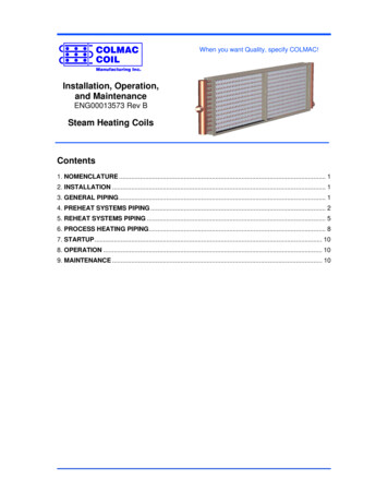
COLMACCOILWhen you want Quality, specify COLMAC!Manufacturing Inc.Installation, Operation,and MaintenanceENG00013573 Rev BSteam Heating CoilsContents1. NOMENCLATURE . 12. INSTALLATION . 13. GENERAL PIPING . 14. PREHEAT SYSTEMS PIPING . 25. REHEAT SYSTEMS PIPING . 56. PROCESS HEATING PIPING. 87. STARTUP . 108. OPERATION . 109. MAINTENANCE . 10
COLMAC1. NOMENCLATUREBSL24481R8FFin PatternFF- Flat Fin, Flat EdgeFR- Flat Fin, Ripple EdgeWF- Waffle Fin, Flat EdgeWR- Waffle Fin, Ripple EdgeType of CoilBS– Basic SteamFS– Steam DistributingTube SizeL– 5/8” ODX - 1” ODFins per Inch4 through 12Finned Height6 through 72 inches(Note: Finned height is equal to thenumber of 5/8” tubes high x 1.5”or 1” tubes high x 3.0”)Finned Length12 through 120 inchesWRRows Deep1 or 2Fin Depth (in direction of airflow)5/8” Rows x 1.2990”1” Rows x 2.598”2. INSTALLATION2.1. Inspection – Upon receipt of equipment, inspect for shortage and damage. Any shortageor damage found during initial inspection should be noted on delivery receipt; this actionnotifies the carrier that you intend to file a claim. If any shortage or damage is discoveredafter unpacking the unit, call the deliverer for a concealed damage or shortageinspection. The inspector will need related paperwork, delivery receipt, and anyinformation indicating his liability for the damage.2.2. Steam coils must be installed in a way that promotes condensate drainage. This will aidin preventing destructive water hammer, freezing, and the buildup of corrosive elementswithin the tubes.2.3. Mounting- Steam coils must be mounted so that tubes are pitched ¼” per foot toward thecondensate return. Colmac can provide coil casings with tubes correctly pitched for anyorientation. Be sure to specify whether tubes are horizontal or vertical, and whetherairflow is horizontal or vertical when ordering.3. GENERAL PIPING3.1. Steam piping must be done in accordance with all applicable national and local codes.3.2. All piping must be self-supporting and flexible enough to allow for thermal expansion andcontraction. The use of flexible connections and/or swing joints is recommended.3.3. Trap each coil independently. Locate trap a minimum of 14 inches below returnconnection of coil when on/off (non-modulating) steam supply valves are used. Locatetrap a minimum of 18 inches (24 inches preferred) below return connection of coil whenmodulating steam supply valves are used.1ENG00013573 Rev B, 10-6-15
COLMAC3.4. Use only traps such as the Inverted Bucket or Float and Thermostatic type which draincontinuously. When modulating steam supply valves are installed, use only a Float andThermostatic trap (DO NOT use Inverted Bucket or Thermodynamic Disk traps).3.5. Minimum operating supply steam pressure is 5 psig.3.6. Never oversize control valves. Bigger is not better.3.7. Coils must be installed so tubes are pitched at least ¼ inch per foot toward condensatereturn.3.8. When condensate must be lifted into overhead or pressurized return mains, a ventedcondensate receiver must be installed with a properly sized steam pressure pump orsome other means of pumping the condensate from the receiver into the return main(See Figures 5 and 6).3.9. Install a vacuum breaker in the steam piping prior to the coil to prevent retention ofcondensate during shutdown. Also install a vacuum breaker on the downstream side ofthe coil when steam pressure is to be modulated. If you use check valves as vacuumbreakers, they should be 15-degree swing checks.3.10. Provide venting of non-condensable gases individually on each coil to ensure maximumheat transfer and minimum internal corrosion. Venting can be with an independentthermostatic vent, or by using a Float and Thermostatic steam trap.3.11. To insure condensate drainage from steam supply lines, install a drip trap.3.12. From the outlet to the steam trap, the piping should be the same size as the outletconnection.3.13. To allow for servicing, manual service valves should isolate the coil and control valve.4. PREHEAT SYSTEMS PIPING4.1. When designing steam heating coils to preheat outdoor air, or to preheat a processairstream which is below freezing temperatures, use the following guidelines.4.1.1. During periods when air temperatures go below 32F (winter months) the possibilityexists for steam coils to freeze and burst. This scenario can be avoided if preheatcoils are correctly designed, piped, and trapped.4.1.2. The use of Colmac type BS – Basic Steam coils is recommended for this type ofservice. This is a single tube, single pass design (no inner tube) that can be appliedwith tubes oriented vertically or horizontally. Colmac type FS – Steam Distributingcoils are not recommended for preheat service where freezing air temperatures areexpected.4.1.3. Modulating steam supply valves are not recommended for preheat systems. Thesteam supply must be either on or off. To control air temperatures, use air bypassdampers. Maintain a minimum steam pressure of 5 psig to coils exposed to airtemperatures below 40F.4.1.4. Design for coil face velocities less than 1000 fpm. Higher face velocities may resultin burst tubes due to coil freeze-up. Design coil ductwork to distribute air evenlyacross the face of the coil, avoiding high velocity streams of low temperature air to hitthe coil face.2ENG00013573 Rev B, 10-6-15
COLMAC4.1.5. Preheat coils can be operated successfully with Inverted Bucket or Float andThermostatic traps that are properly sized according to the trap manufacturersrecommendations. Thermodynamic Disk type traps operate intermittently (alternatelyfill and dump condensate) and should not be used on any steam heating coil.4.1.6. Pipe preheat coils according to Figures 1 and 2:3ENG00013573 Rev B, 10-6-15
COLMAC4ENG00013573 Rev B, 10-6-15
COLMAC5. REHEAT SYSTEMS PIPING5.1. The following guidelines apply to steam heating coils designed to reheat air that hasalready been preheated or has been recirculated from a heated space or process.5.1.1. Normally, steam coils installed in reheat applications are fed by a modulatingsteam supply valve operating in response to changing air temperature. For this typeof system, Colmac type FS – Steam Distributing coils are recommended. Steamdistributing coils are built with an inner distribution tube having orifices which admitthe live steam into the annulus between the outer and inner tubes. The inner tubeorifices are carefully spaced along the length of the coil tube to effectively distributesteam over the entire face of the coil. This feature is important during periods of partload when the steam supply valve is modulating down to low steam pressures.5.1.2. Type FS steam coils can be installed with tubes oriented vertically or horizontally.5.1.3. It is critically important when installing type FS coils that only properly sized Floatand Thermostatic type steam traps are used. This type of trap operates tocontinuously drain the coil of condensate at all load conditions. Inverted Bucket trapsshould not be used and will not operate correctly when modulating steam supplyvalves are installed. Thermodynamic Disk traps operate intermittently (alternately filland dump condensate) and should not be used on any steam heating coil.5.1.4. It is also critical when modulating steam supply valves are installed that vacuumbreakers are installed both at the coil inlet downstream of the modulating controlvalve, and between the coil outlet connection and the steam trap. During part loadoperation, the modulating supply valve may reduce the steam pressure in the coil tothe point that a vacuum can result in the coil tubes. Unless vacuum breakers areproperly installed, condensate will be pulled into the coil causing premature failuredue to Thermal Shock (pitting corrosion) and/or Hydraulic Shock (water hammer).The vacuum breakers serve to admit air into the coil during periods of low load,reducing coil capacity to the desired output, while allowing the condensate to becontinuously and effectively drained away.5.1.5. Type FS-L Steam Distributing coils (5/8” outer tubes) can be supplied with onesupply connection for finned lengths up to 72”. FS-L coils with finned lengths over 72”must be fed with supply steam from both ends of the coil. Type FS-X SteamDistributing coils (1” outer tubes) can be supplied with one supply connection forfinned lengths up to 144”.5.1.6. Pipe reheat coils with modulating steam supply valves according to Figures 3 and4:5ENG00013573 Rev B, 10-6-15
COLMAC6ENG00013573 Rev B, 10-6-15
COLMAC7ENG00013573 Rev B, 10-6-15
COLMAC6. PROCESS HEATING PIPING6.1. Figures 5 and 6 below show recommended piping arrangements for process heatingcoils with modulating and non-modulating steam supply valves having an overheadreturn.6.2. A vented receiver as shown in figures 5 and 6 must be used whenever condensate mustbe lifted into overhead or pressurized return mains. Consult the steam trap and pumpmanufacturer for specific design recommendations for these types of systems. Acondensate receiver with pump is the only certain way to insure that condensate iseffectively cleared from the coil under all operating conditions in these types of systems.8ENG00013573 Rev B, 10-6-15
COLMAC9ENG00013573 Rev B, 10-6-15
COLMAC7. STARTUP7.1. Once the coil is installed, it should be pressurized to 100 psig with dry nitrogen. The coilshould be held at this pressure for 15 minutes to insure there are no leaks.7.2. Prior to initial startup, clean coil with a commercially available coil cleaner.7.3. To prevent plugging of tubes, clean the piping system and blow down all strainers prior toinitial startup.7.4. On startup, feed steam to the coils slowly to avoid thermal shock loadings.7.5. Make sure the steam has been on for a minimum of 15 minutes prior to starting the fansor opening dampers.7.6. During initial startup, tighten all bolted connections once the system stabilizes atoperating temperature.8. OPERATION8.1. Keep operating pressures at or below the design limit.8.2. Airflow should not vary by more than 20 % anywhere on the coil surface.8.3. Air velocities should be maintained between 200 and 1500 feet per minute.8.4. Drain coil to prevent corrosion during shutdown.9. MAINTENANCE9.1. To insure proper coil performance, finned surfaces and tubes should be cleaned on aregular basis using a commercially available coil cleaner. Clean finned surface from theair leaving side.9.2. All drip traps, dirt pockets, steam traps, vacuum breakers, air vents, strainers, and valvesshould be flushed and inspected regularly.9.3. A boiler water treatment should be done on occasion to remove dissolved oxygen andcarbon dioxide.10ENG00013573 Rev B, 10-6-15
COLMAC11ENG00013573 Rev B, 10-6-15
COLMACCOILManufacturing Inc.Colmac reserves the right to change product design and specifications without notice.For more information on Colmac products call us at 1-800-845-6778 or visit us online at:WWW.COLMACCOIL.COM
2.2. Steam coils must be installed in a way that promotes condensate drainage. This will aid in preventing destructive water hammer, freezing, and the buildup of corrosive elements within the tubes. 2.3.