Transcription
INSTALLATIONINSTRUCTIONSBATH ENCLOSURESa product of AlcoaMade ByTel: 800-643-1514Fax: 870-234-3181www.alumaxbath.com792 SERIES1-800-669-9867STIKSTALLCORNER SHOWER ENCLOSURETMCopyright Alumax Bath Enclosures 1997. All rights reserved.G037110748-1-06
LIMITED WARRANTY AND REMEDYA LUMAX B ATH E NCLOSURES warrants to its dealers, customers, and all subsequent purchasersand users, that the products supplied by it shall be free from material defects in materialand workmanship for a period of one (1) year after shipment, provided they are installed andmaintained according to A LUMAX B ATH E NCLOSURE 's recommended practices and installationinstructions. This warranty shall apply only to defects appearing within one (1) year fromthe date of shipment, and provided that A LUMAX B ATH E NCLOSURES is promptly notified inwriting of such defects. The sole and exclusive remedy with respect to the above warrantyor with respect to any other claim relating to defects or any other condition or use of theproducts supplied by A LUMAX B ATH E NCLOSURES , however caused, and whether such claimis based upon warranty contract, negligence, strict liability, or any other theory, is limitedto repair or supply of such products, or repayment by A LUMAX B ATH E NCLOSURES of thepurchase price paid for it, at A LUMAX B ATH E NCLOSURE 's option.A LUMAX B ATH E NCLOSURES does not make any other representations or warranties, express orimplied, including, but not limited to, any implied warranty of merchantability and anyimplied warranty of fitness for a particular purpose. In no event shall A LUMAX B ATHE NCLOSURES be liable for special, direct, indirect, or consequential damages, including, butnot limited to, loss or use of profits.Dealers agree to pass on to its customers and users in writing A LUMAX B ATH E NCLOSURE 'sWarranty and Remedy as set forth above.Laws and building and safety codes governing the design and use of bath enclosures varywidely. A LUMAX B ATH E NCLOSURES does not control the selection of product configurations,operating hardware or glazing materials, and assumes no responsibility therefor.INSTALLATION NOTESUnpack your unit carefully and inspect for freight damage. Lay out and identify all partsusing the instruction sheets as a reference. Before discarding the carton, check for smallhardware bags that tend to fall to the bottom of the box. If any parts are damaged ormissing, refer to the descriptions noted in the instructions when contacting your dealer forreplacements.Handle the glass panels carefully and protect the edges. Safety tempered glass is veryresistant to breakage, but it can be broken by banging the edges against a hard surface. Thesharp corners of the panels can damage tile and floor surfaces, so do not remove anyprotective devices until you are ready to install the glass.Please wear safety glasses whenever drilling or cutting. When drilling holes in ceramic tileor marble, use a center punch and hammer to carefully break the surface glaze so the drillcan start without skidding.To install your A LUMAX S TIKSTALL Shower Enclosure you will need the following: tapemeasure, level, #2 Phillips screwdriver, drill, 1/8" and 3/16" drill bits, 3/16" wrench,hacksaw, mallet or hammer, wood block, razor or sharp knife, pencil, glass cleaner, andcaulking (clear silicone recommended). Optional tools include a miter box for cutting partsto length, files, center punch and masking tape.G037110748-1-06Page 2 of 10
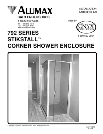
792 STIKSTALL PARTS LISTA.B.C.D.E.F.G.H.2 Curb Sections (with weep slots) J . 1 Fixed Glass PanelT. 1 Latch2 90 Anchor PlatesK. 1 90 PostU. 1 Deflector16 #8 x 1/4" Truss Head Screws L. 2 Pcs. Horiz. Glazing Vinyl W. 1 Handle2 Header SectionsM. 1 Assembled Door Panel X. 4 Plastic Washers2 Wall JambsN. 4 Pcs. Vert. Glazing Vinyl Y. 2 Plastic Bushings10 Plastic Wall AnchorsP. 1 Strike Jamb (Magnetic) AA. 2 Set Screws10 #8 x 2" Truss Head ScrewsR. 2 Snap-in Fillers2 Plastic Setting BlocksS. 1 Handle VinylLRMNPWcZXYSCTAAWXURPage 3 of 10G037110748-1-06
The A LUMAX S TIKS TALL framework has been designed to work with a varietyof different door types. To ensure correct installation, this 792 Instruction Sheetis designed to be used by itself with a 790 Framed Pivot Door or with an instructionsupplement packed with a 390 Frameless Pivot Door, a 790i Intre-Hinge Door ora 1090 Heavy Frameless Pivot Door.Each step in this primary instruction sheet will indicate whether it applies toall door types or if a supplement should be used. If your door panel kit does nothave an instruction supplement, then contact your dealer for the proper instructions.790 door panel kits are covered in this instruction, therefore will not come with aseparate instruction supplement.DOORS1 - ALLThe A792 SLUMAXTIK S TALL Shower Enclosure iscompletely reversible and may be installed pivot-left orpivot-right (hinge-left or hinge-right). The door may pivotfrom the wall or from the center post. Using the diagram,determine the correct position for the door in your particularSTIKSTALL installation. This instruction sheet depicts apivot-right (hinge-right) installation.NOTE: Fixed glass panel size should be determined byformulas shown on A LUMAX detail sheets.CAUTION: For safety reasons, the door panel mustalways open outward.DOORS2 - ALLAssemble the two curb sections [ A] (withweep slots) by sliding a 90 anchor plate [ B] intothe mitered ends and forcing the sections together.The weep slots in the curb must be to the inside.Using the slotted holes in the anchor plate as aguide, drill matching 1/8" holes into the curbs.Secure the anchor plate to the curb with four #8 x1/4" truss head screws [ C]. As you tighten thescrews, be sure the mitered ends are forced tightlytogether. To increase the rigidity of the miteredjoint, drill and install two more screws throughthe round holes in the bracket.Assemble the two header sections [ D] in the samemanner and set the assembly aside.aerlAG037110748-1-06essAdyPage 4 of 10delbm
DOORS3 - ALLMeasure the opening at the bottom of theshower stall and trim the ends of the curb assembly[A] (with weep slots) to fit the shower sill. Thecurb should sit near the centerline of the sill. Ifrequired, use a file to round the lower ends of thecurb assembly to fit the shower sill properly.Using a 3/16" drill bit, drill the interior face of thecurb assembly on both ends as shown.Reposition the curb assembly on the shower silland mark its position with a pencil line along theinterior and exterior base.DOORS4 - ALLPlace the two wall jambs [ E] into the ends ofthe curb assembly [A]. Masking tape may be usedto hold the curb in place during this operation.Plumb the jambs and mark the hole locations onthe wall. Remove all parts and drill the walls formounting hardware.For tile or marble walls, drill six 1/4" diameterholes and insert the plastic wall anchors [ F].Attachments to fiberglass or acrylic units can bemade in two ways. If a reinforcement is built intothe wall of the unit, drill six 1/8" holes to installmounting screws directly into the reinforcement.If walls are not reinforced, drill six 1/4” holes andinstall plastic wall anchors or toggle bolts (togglebolts not supplied by A LUMAX ).DOORS EXCEPT 10905 - ALLWipe the shower walls and sill, curb assembly[A] and wall jambs [ E] with a clean, dry cloth toremove any dust or debris. Apply a 1/4" bead ofcaulk along the inside of both of the pencil linesmarked in Step #3. Carefully replace the curb inthe exact position marked. Caulk the inside of thecurb ends where they meet the wall. Caulkgenerously around the anchor plate [ B], screws[C], and the inside of the mitered joint.Replace both wall jambs and attach to the wallswith six #8 x 2" truss head screws [ G].Page 5 of 10G037110748-1-06
DOORS6 - ALLPlace two setting blocks [ H] into the curbassembly [A] as shown to support the fixed glasspanel [J]. The setting blocks should be positionedapproximately 3" from each corner of the glasspanel. Remove any protective strips from theglass panel and set it into place on the settingblocks approximately 1/2" into the wall jamb [ E].A strip of masking tape 1/2" from each verticaledge of the glass will aid alignment.NOTE: Obscure glass panels should be installedwith the rough surface of the glass to the exteriorof the unit. Deco or etched glass panels shouldhave the patterned surface to the inside.Press the 90 post [ K] into the curb assembly. Itshould overlap the glass panel by 1/2". Use maskingtape to hold the post in position temporarily.DOORS7 - ALLHold the 90 post [ K] plumb and carefullymeasure horizontally from the top of each walljamb [E] to the outside edge of the post. Add 3/16"to each measurement to find the correspondingdimension on the header assembly [ D] (from theoutside mitered edge to the squared ends) andtrim the header assembly to fit.NOTE: To facilitate out of plumb walls, the 1/2"glass bite may be varied from 1/4" to 3/4".Using a 3/16" drill bit, drill the interior face of theheader assembly on both ends as shown.DOORS8 - ALLPress the header assembly [ D] over the walljambs [E] and the 90 post [ K]. Check the post forplumb. Adjust as required by varying the overlapof the header over the wall jambs. You may needto trim the ends of the header where it meets thewall. The minimum horizontal dimension for thedoor opening is the door panel width (see thegraphic in Step #9) plus 3/4", maximum is the doorpanel width plus 1 3/4".Using the holes in the ends of the header and curbas a guide, drill four 1/8" holes into the wall jambs.Drill two 1/8" holes thru the header and curb intothe 90 post as shown, then enlarge the two outerholes with a 3/16" drill for clearance on the selftapping screws. Secure the header and curb to thewall jambs and post with six #8 x 1/4" truss headscrews [C].CAUTION: Slide the glass panel away from thewall jamb before drilling to prevent breakage.G037110748-1-06Page 6 of 10
9Press the hinge jamb/door panel assembly [*A ] andstrike jamb [*B ] (with magnetic strip) over the wall jamband/or framing posts. Refer to Step #1 of the STIK STALLinstruction sheet for the proper handing of the door.Adjust the door panel assembly so there is 1/4" clearancebetween the strike jamb and the strike edge of the glassdoor panel in the closed position. Mark the location of thehinge jamb on the wall jamb (or post).NOTE: The magnetic strip on the strike jamb must facethe exterior and the door panel must open outward.10Snap both fillers*R[ ] into the curb and header betweenthe hinge and strike jambs with the raised lips to the exterior.Center the curb filler between the hinge and strike jamb (usemasking tape to hold in position).NOTE: The snap-in fillers should be exactly 7/16" longerthan the door panel width.11 Pull the bottom end of the hinge jamb tight to thecurb filler [*R ] and plumb the jamb. Drill two 1/8" holesthru the hinge jamb and into the wall jamb (or post) 3/8" to3/4" from the wall and approximately 1/4" vertically fromthe ends of the jamb. Drill a third hole centered betweenthe first two and enlarge the outer holes with a 3/16" drillfor clearance on the self-tapping screws. Attach thehinge jamb/door panel permanently with three #8 x 1/4"truss head screws [*C ].Slide the header filler [*R ] tight against the hinge jamb.Push the strike jamb [*P] tight against the fillers top andbottom. With the hinge jamb plumb and both fillers tightbetween the two door jambs, the strike jamb also will beplumb and parallel to the hinge jamb. Attach the strikejamb in the same manner as the hinge jamb.Page 7 of 10EPH-N00-060969-11-03
12Slide the latch [*T ] with magnet onto the strike edgeof the door panel. Close the door and slide the latch up ordown until the two magnetic strips are aligned. Use apencil or masking tape to mark the location of the latch onthe door.Wrap the latch vinyl [*S ] over the edge of the door glassbetween the marks and carefully drive the door latch ontothe door panel. Spraying glass cleaner or water onto thevinyl will make assembly easier.Close the door and check for proper operation of themagnetic catch.13Determine the desired handing of the deflector[*U ]. The deflector leg must go to the inside of the unitand the notch fits under the hinge rail as shown in thedrawing at right. To determine the door panel widthmeasure the distance from the edge of the hinge rail to thefar edge of the glass door panel. The deflector should becut to Door Panel Width - 7/16". Press the deflector firmlyon the bottom edge of the glass as shown.14Locate the handle [*W] that has no Set Screws.Place a Plastic Bushing [*Y] in the top handle hole thenplace a Plastic Washer [*X ] against the glass. Place thehandle without Set Screws against the Plastic Washer andinsert the threaded end of the Cone Head Screw [ *Z ]through the bushing into the threaded insert in the end ofthe handle and tighten. Repeat the procedure for thebottom hole. Place Plastic Washers [ *X ] against theopposite side of the glass and press the remaining handle[*W] over the end of the Cone Head Screw. While holdingthe handles firmly against the glass tighten the Set Screws[*AA ].EPH-N00-060968-28-03Page 8 of101/8"
DOORS15 - ALLInspect the pieces of black glazing vinyl,and note the two different profiles. The smallershape [ N] is installed vertically and the largershape [L ] is installed horizontally. For structuralstrength and maximum water resistance, thesevinyls are designed to fit tightly between the glassand framing. To speed installation, use glasscleaner for lubrication and a small block of wood topress the vinyl into place.1/4" GLASSREQUIRES:V-219V-2203/16" GLASSREQUIRES:V-226V-225DOORS16 - ALLCut four pieces of the smaller vinyl [ N] 1"longer than the vertical opening (to preventgapping from shrinkage) and trim the ends on a45 angle. Using the masking tape guides, centerthe glass panel [ J] in the frame. Cut four short (1"- 2") pieces of the small vinyl and press into bothjambs on each side to hold the glass temporarily.Take one of the long pieces of vinyl, and startingon the outside exterior jamb, press each end intothe frame and work toward the middle. Be carefulnot to stretch the vinyl. Install the other threepieces in a similar fashion.DOORS17 - ALLCut four pieces of the larger vinyl [ L ] 1/2"longer than the horizontal opening and trim theends on a 45 angle. Install the top exterior vinylstarting at both ends and working toward themiddle. Be careful not to stretch the vinyl.Install the top interior vinyl and the two bottomvinyls in the same way.Page 9 of 10G037110748-1-06
DOORS18 - ALLCarefully caulk the interior jamb-to-walland curb-to-base joints. For appearance, you maywish to caulk the exterior joints as well. Werecommend you wait twenty-four hours before thefirst shower to allow the caulking to cure properly.To keep your Alumax Bath Enclosure looking like new we recommend the AlumaxShowerBright Consumer Maintenance Kit. The Consumer Maintenance Kit surface should beapplied every 45 to 60 days. To purchase or for more information contact your dealer. Ourdealers have the materials to do a professional ShowerBright restoration. For best resultsprofessional restorations should be performed a maximum of once every three months. Contactyour dealer for more information. New units with factory supplied ShowerBright coating havea limited lifetime warranty. For daily cleaning the simplest and preferred method is to wash theunit with clean water and dry with a soft cloth. Do not use scouring pads, sharp instruments,or acid-based cleansers to clean the unit.Consumer kits will be sold direct, consumers will need to go to dealers for professionalrestoration and new units can be purchased with the permanent coating. Consumer kitmaterials need to be applied every 45 to 60 days, pro materials to be applied once quarterly maxand factory has limited lifetime.G037110748-1-06Page 109 of 10
TALL Shower Enclosure is completely reversible and may be installed pivot-left or pivot-right (hinge-left or hinge-right). The door may pivot from the wall or from the center post. Using the diagram, determine the correct position for the door in your particular S TIKS TALL installation. This instruction sheet depicts a pivot-right (hinge-right .