Transcription
ByWintriss Controls GroupAddendum – SMI 2 – User GuideShopFloorConnect Machine Interface1146200 – Rev. BDecember 2, 2020SFC Support Hotline 800-586-8324 Option 3 8-5 Eastern Time
ContentsMain Menu. 3Main Menu Icon/Button Selections . 4Dashboard . 5Downtime. 6Job Manager . 7Load Next Job . 8Preset . 9Batch Segment Preset . 10Admin Menu . 11Security Settings. 12Confirm Reset To Factory Defaults . 13About SMI . 14Multipliers . 15Utilities . 16Additional Settings - Icon/Button Selections . 17Screen Defaults . 18Forced Dialog Settings . 19Scanner Defaults . 20Production Parameter Download . 21Production Settings . 22Network Settings. 23Network IP Settings. 24Wireless Settings . 25Input Settings . 26Input Setup. 27Cycle Input Setup . 28Run/Idle Input Setup . 29Rate Calculation . 30Analog Setup Menu. 31Enable Inputs . 32Hold State Settings . 33SMI 2 Job Manager Settings. 34AddendumSMI 2 User GuideDec 2020Rev. B1146200APage 1
Figures at End of User GuideFigure 1 – SFC Machine Interface 2Figure 2 – SFC Machine Interface 2 (Press Wiring Diagram)Figure 2 - SFC Machine Interface 2 (24 VDC Wiring Diagram)ADDENDUM - SMI 2 User GuideThis User Guide is intended to be used – on an interim basis - in conjunction with the SMI 2 usermanual while the final manual is completed. Included are explanations of the modified SMI 2 Menusand new settings.NOTE: There is a 30-character limit on all entry fields (with one exception – See below). Allowablecharacters include numbers, upper and lowercase letters, spaces, and the special characters:. - [ ] { } \ * # % Data can be entered into the fields manually, or by the use of a scanner connected to the SMI 2’s USBport.The one exception to the 30-character limit is the Primary when it is set to ‘Tool # (123)’. Thisparticular primary type is intended to match the Wintriss SmartPAC 1 and SmartPAC 2 controls and islimited to 7 numeric characters only.Note: Not all of the available Icon/Buttons and their data fields in the SMI 2 are applicable to allmachine types. When a data field does not apply to a specific application, it can be hidden. This guideshows all the data entry fields. If your SMI 2 does not show a particular field, it is likely hidden becauseit is not needed. To identify which Icon/Buttons and their data entry fields can be hidden from themain menu, refer to the Icon/Buttons table (See page 4).AddendumSMI 2 User GuideDec 2020Rev. B1146200APage 2
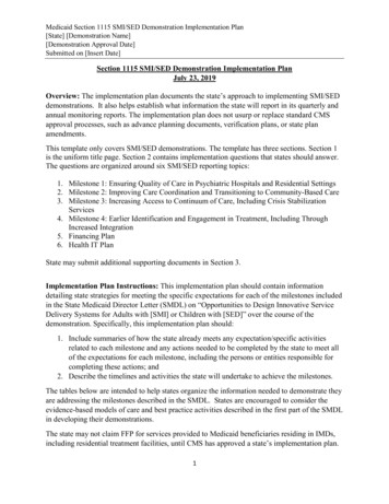
Figure 1- SMI 2 R2 Main MenuMain MenuThe Banner at the top of the main menu is color-coded for the five different SFC states: Green(Running), Blue (Idle), Red (Unplanned), Yellow (Changeover), Purple (Planned). It also shows currentstatus and duration as well as the current count info and production rate.AddendumSMI 2 User GuideDec 2020Rev. B1146200APage 3
These are the main menu Icon/Buttons and their functions (an *** indicates that the button may behidden via a selection in the ‘Admin Settings’ menu):Main Menu Icon/Button SelectionsSelect the ‘Operator’ icon to enter the operator number or name (Optional Scan Field).Select the ‘Rejects’ (scrap) icon to manually enter the desired quantity of defective parts.Select the ‘Job Manager’ icon to enter job related information, start a new job or to endthe current job.Select the ‘Dashboard***’ icon to show MTBF (Mean Time Between Failures) and AnalogChannel values.Select the ‘Hold State***’ to hold the current Planned/Unplanned downtime orChangeover state and prevent the SMI from counting until it is selected again anddisabled. Hold State is often used when setting up the machine.Select the ‘Return to Production’ icon when first powering up, to end a downtime eventor if a count preset is reached. By selecting ‘Return to Production’ icon it will change thestate to an idle state.Select the ‘Dialog Menu’ icon to select an applicable Dialog Reason code as to why themachine is down (Used when machine is not running and before or after a forced dialogreason is entered).Select the gear icon to access the ‘Admin Menu’.Select the question mark icon (bottom left) for a series of help topics related to themenu or menu item that is in view.AddendumSMI 2 User GuideDec 2020Rev. B1146200APage 4
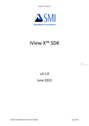
Figure 2 - Dashboard MenuDashboardThe DASHBOARD menu shows MTBF (Mean Time Between Failures) and the Analog values from anyconnected analog sensor (e.g. Temperature, Current, Pressure, etc.).Mean time between failures (MTBF) refers to the average amount time between Unplanned Downtimeoccurrences.Note: The Dashboard menu is disabled by default and is not fully functional. It will be available soon ina future release. For more information on this feature and availability, please contact SFC TechnicalSupport 800-586-8324 Option 3).AddendumSMI 2 User GuideDec 2020Rev. B1146200APage 5
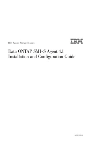
Figure 3- The Downtime MenuDowntimeUse this menu to choose the appropriate downtime reason. Use the ‘Previous’ or ‘Next’ buttons todisplay the previous or next set of reasons. Press the ‘Cancel’ button to skip setting the downtimereason and return to the Main Menu. Press the reason to select it as the current downtime reason.Note: Downtime reasons can be 30 characters or less.AddendumSMI 2 User GuideDec 2020Rev. B1146200APage 6
Figure 4 - The Job Manager MenuJob ManagerUse this menu to Scan/Enter Job information - Primary (e.g. Tool, Part, Mold, Fixture, SKU, Material,Item, etc.) is required.Optionally Scan/Enter Job Number, Preset (qty. parts to be produced), and Batch.The BATCH allows the operator to set the quantity of parts to make for this batch. When the quantityis reached, the inhibit relay is opened. Setting a preset to zero disables the preset. If ‘Stop On Preset’is enabled, the inhibit relay will be opened when the preset is reached.Select ‘End Job’ to terminate the current Job. Select ‘Next Job’ to consume the next job on theschedule. The ‘Next Job’ is enabled/disabled using the ‘Scheduler’ on the Production Setting menu.Select ‘Load Job’ to start a new job using the primary and secondary items displayed.Select ‘#’ to modify the count multiplier values. Select ‘Update’ to save the Preset and Batch valuesyou entered for the currently loaded job.Select the ‘Chain’ icon to link the primary/job #, so when the operator enters or scans a primary it willautomatically bring them to the Job Number field. Select both ‘Chain’ icons to link all 3 fields’ primary,Job #, and Preset.AddendumSMI 2 User GuideDec 2020Rev. B1146200APage 7
Figure 5- Load Next JobLoad Next JobThe ‘Load Next Job’ menu launches when the Next button on the Job manager is selected andScheduler is enabled. Job information from the ShopFloorConnect Scheduler is displayed and getsconsumed by selecting ‘Load’.AddendumSMI 2 User GuideDec 2020Rev. B1146200APage 8
Figure 6 - Setting the Preset (set up for a scanner)PresetSelecting the scan/edit to the right of ‘Preset’ allows the operator to enter the total quantity of partsto be made. Figure 6 above shows the field set up for scanning.When the quantity is reached, the SMI’s inhibit relay will open and stop the machine if ‘Stop onPreset’ is enabled and the machine’s stop circuit is wired in series with the inhibit relay.When ‘Stop on Preset’ is disabled the SMI’s inhibit relay will not open and the operator can continuerunning and the message ‘Preset Reached Continuing Operation’ will appear.Setting a preset to zero disables the preset.Note: To disable and/or enable your Preset (See Admin – Multipliers -Figure 29)When ‘Stop on Batch’ is disabled, the SMI’s inhibit relay will not open, the operator can continuerunning, and the message ‘Preset Reached Continuing Operation’ will appear.Note: To disable and/or enable your preset please go to Admin Multipliers - Figure 8.AddendumSMI 2 User GuideDec 2020Rev. B1146200APage 9
Figure 7- Batch Segment Preset ValueBatch Segment PresetThe ‘Batch Segment’ menu allows the operator to enter a batch quantity. Often it’s programmed tostop the machine when a certain quantity of parts is reached so a basket can be switched out or to QCa part after X number of cycles.When ‘Stop on Batch’ is disabled, the SMI’s inhibit relay will not open, the operator can continuerunning, and the message ‘Preset Reached Continuing Operation’ will appear.Note: To disable and/or enable your presets please go to ‘Admin’ Counts & PresetsAddendumSMI 2 User GuideDec 2020Rev. B1146200APage 10
Figure 8- Admin MenuAdmin MenuIcon/Button SelectionsSelect ‘Security Settings’ to set or change Admin and Adjust Scrap passwords. Also, toreset all settings to their Factory Defaults.Select ‘Settings’ to set various systems parameters like Screen and Scanner defaults,Network settings, State Hold and SFC Parameter Downloads.Select ‘About SMI’ for SMI Firmware Versions, password 5 digit code and Supportcontact info.Select ‘Counts & Preset’ to change the counter preset settings & modify countingparameters.Select ‘Utilities’ to perform miscellaneous tasks like Copying Log files, System Rebootand Start Remote AccessAddendumSMI 2 User GuideDec 2020Rev. B1146200APage 11
Figure 9 - Security SettingsSecurity SettingsWhen the ‘Password Required to Access Admin’ is set to ‘Enabled’, the user will be required to enter apassword to access the admin Menus.When the ‘Password Required to Adjust Rejects’ is set to ‘Enabled’, the user will need a password tochange the reject count.The ‘Change Password’ allows you to reset the system password (Note: default password is 0).AddendumSMI 2 User GuideDec 2020Rev. B1146200APage 12
Figure 10 – Confirm Reset to Factory DefaultsConfirm Reset To Factory DefaultsWarning: Pressing the Confirm button will erase all settings you have made and return the SMI 2 to itsoriginal factory settings.Note: This includes all Downtime Reasons saved to the SMI 2. These will need to be resent fromShopFloorConnect.Press the ‘Cancel’ button to keep your settings and return to the previous menu.AddendumSMI 2 User GuideDec 2020Rev. B1146200APage 13
Figure 11- About SMIAbout SMILists code versions, password code and SFC Support contact information.AddendumSMI 2 User GuideDec 2020Rev. B1146200APage 14
Figure 12- Multipliers MenuMultipliersThe Operations/Cycle should be used when one or more cycles of the machine are requiredto produce a completed part.The Cycle Count Multiplier value is the number of parts created after a single cycle.The Rejects Count Multiplier value is the number of Scrap/Rejects that will be tallied anddeducted from the Good Parts Count when the Scrap/Rejects input is actuated.Note: the Scrap input must be enabled to use this input. Often it is connected to an automatedscrap handling system or a simple N/C momentary switch for manual entry.Enable ‘Stop On Total Parts Preset’ to open the SMI 2 Inhibit Relay and stop the machine when thetotal quantity of items/parts have been reached.Enable ‘Stop On Batch Preset’ to open the SMI 2 Inhibit Relay and stop the machine when a batchquantity of items/parts have been reached.Note: Provided the machine’s stop circuit is wired in series the inhibit relay.The ‘Reset Batch Count’ sets the Batch Segment Count to zero, not the Batch Segment Preset.AddendumSMI 2 User GuideDec 2020Rev. B1146200APage 15
Figure 13- UtilitiesUtilitiesThe ‘Copy Log file to USB disk’ allows the operator to copy the error log file to the USB disk.The ‘Copy Settings to USB Disk’ allows the operator to copy critical settings to the USB disk.The ‘Force Code Download’ forces the SMI to reboot and prompt the user to perform a CodeDownload.The ‘Reboot System’ restarts the SMI 2.‘Calibrate Screen’ is for calibrating the touch screen.The ‘Start Remote Access’ starts an application which gives the user the ability to control the SMI fromtheir computer (this is a support function and should be used with care).Note: A purple square next to the Utilities Start Remote Access button and in the lower left corner ofthe Main Menu indicates that Remote Access is started.AddendumSMI 2 User GuideDec 2020Rev. B1146200APage 16
Additional Settings - Icon/Button SelectionsSelect ‘Screen Defaults’ – to change the language of the SMI, hide the changeoverand/or Dashboard button.Select ‘Forced Dialog Settings’ - to Enabled/Disable when the operator is forced toselect a downtime reason before restarting the machine.Select ‘Scanner defaults’ to select the production fields you would like to scan in.Select ‘SFC Settings’ - to enable SFC to download the production parameters to theSMI when a new production segment is started (loading a new job).Select ‘Production Settings’ - to set the frequency the SMI calculates the speed ofthe machine and sets a production Idle Timer.Select ‘Network Settings’ - to setup to Network related parameters.Select ‘Input Settings’ - to program input off delay timers, to enable Run/Idle,Scrap Sense and Analog Inputs. Also, to enable Decrement on Scrap setting.Select ‘Hold State Settings’ – to set and/or change your hold state settings.Select ‘Job Manger Settings’ - to set the primary, job aliases, and to hide variousparameters.AddendumSMI 2 User GuideDec 2020Rev. B1146200APage 17
Figure 14 - Screen Default SettingsScreen DefaultsLanguages that SFC currently supports are English, Spanish, Italian, and German.Check ‘Hide Changeover Button’ to hide the canned changeover dialog reason in thedialog menu.Check ‘Hide Dashboard Button’ to hide the dashboard button on the main menu.Check standard if you are not using the parent/child function. If the SMI is parent select theParent radio button. If the SMI is Child to a Parent SMI select the Child radio button.AddendumSMI 2 User GuideDec 2020Rev. B1146200APage 18
Figure 15- Forced Dialog SettingsForced Dialog SettingsWhen enabled, the ‘Forced Dialog’ mode forces the operator to select a downtime reason beforerestarting the machine.The ‘AutoBackFill’ mode automatically replaces the idle time with any selected downtime event.The ‘Manual Backfill’ mode requires the user to specify whether to Keep or Change the previousreason.The ‘Forced Dialog Timer’ sets a grace period, after which the operator will be forced to enter adowntime code in order to restart the machine.AddendumSMI 2 User GuideDec 2020Rev. B1146200APage 19
Figure 16- Scanner Default SettingsScanner DefaultsCheck any of the boxes for items you want the operator to scan.AddendumSMI 2 User GuideDec 2020Rev. B1146200APage 20
Figure 17- Production Parameter Download MenuProduction Parameter DownloadCheck ‘Get Count Factors’ to download the Operations Per Cycle and Parts Per Cycle count modifiersettings at the start of a new job.Check ‘Get Production Idle timer’ to download the Production Idle timer setting at the start of a newjob.Check ‘Get Forced Dialog Timer’ to download the Forced Dialog Timer setting at the start of a new job.AddendumSMI 2 User GuideDec 2020Rev. B1146200APage 21
Figure 18 - Production SettingsProduction SettingsThe ‘Calculation Interval’ sets the frequency at which the SMI calculates the speed (Production Rate)of the machine. Set this to the time it takes to make 10 cycles, or 15 seconds, whichever is greater.The ‘Idle Timer’ sets the time the SMI will wait between machine cycles before it switches the statefrom Running to Idle. As a starting point, set this value to 1.5 times the expected normal timebetween cycles.The ‘Max Pulse Period’ controls an optional setting to improve the rate calculation in someapplications. Refer to the user manual or contact SFC support for more details.The ‘Production Rate Units’ specifies the speed units that the SMI will display (Cycles/Minute,Parts/Hour, etc.). Select ‘Production Rate Units’ to cycle through the available selections.AddendumSMI 2 User GuideDec 2020Rev. B1146200APage 22
Figure 19- Network SettingsNetwork SettingsSelect the Network IP Settings button to input Static IP address settings.Select the Wireless Settings button to configure wireless settings, SSID, Passcode etc.Note: For your SMI 2 to connect to your network wirelessly, the Optional Wireless Kit (802.11 B/N/B)must be Factory installed at time of initial order. The kit includes an adapter board and antenna.Compatible with AC and 24 VDC models with enclosure. (For more information on wirelessspecifications, setup and retrofit options, please consult the full manual or contact SFC TechnicalSupport 800-586-8324 Option 3).AddendumSMI 2 User GuideDec 2020Rev. B1146200APage 23
Figure 20 – Network IP SettingsNetwork IP SettingsThis menu enables the user to set the network parameters for a static IP address or allow the DHCPserver to provide the address.AddendumSMI 2 User GuideDec 2020Rev. B1146200APage 24
Figure 21 – Wireless SettingsWireless SettingsTo set the SMI-2 up to use a wireless access point, you must provide the following information: SSID,and Pass Key (Password Key)AddendumSMI 2 User GuideDec 2020Rev. B1146200APage 25
Figure 22- Input SettingsInput SettingsThe ‘Input Setup’ provides access to settings associated with the Cycle Input, Run/Idle inputs, RateCalculation, and Analog Inputs.The ‘Enable Inputs’ shows the current on/off state of the SMI’s inputs. The ‘Enable Inputs’ gives accessto the setting the way the SMI interprets state changes using the Cycle and Run/Idle inputs. Also, the‘Enable Inputs’ is used to set the Scrap Sense Input, Decrement on Scrap, and the Analog Channels.AddendumSMI 2 User GuideDec 2020Rev. B1146200APage 26
Figure 23- Input SetupInput SetupThe ‘Cycle Input’, ‘Run/Idle Input’, and ‘Analog Inputs’ allows access to the settings associated withthose inputs.The ‘Rate Calculation’ provides access to the ‘Pulses Per Units’ setting which specifies the number ofactuations of the cycle input that represents one increment of the speed units.To activate the ‘Rate Calculation’, the Calculation Interval on the Production Settings menu must beset to Instantaneous.AddendumSMI 2 User GuideDec 2020Rev. B1146200APage 27
Figure 24- Cycle Input SetupCycle Input SetupThe ‘Cycle Input’ allows the operator to modify the cycle input signal to match the requirements of theSMI.The choices are ‘No additional Timing’ and ‘Off Delay’.The ‘No additional Timing’ selection makes no modifications to the input signal.The ‘Off Delay’ selection delays the change to off.This has the ability to count all the pulses that occur within the time window as one.AddendumSMI 2 User GuideDec 2020Rev. B1146200APage 28
Figure 25 - Run/Idle Input Setup MenuRun/Idle Input SetupThe ‘Run/Idle Input’ allows the operator to modify the run/idle input signal to match the requirementsof the SMI. The choices are ‘No additional Timing’ and ‘Off Delay’.The ‘No Additional timing’ selection makes no modifications to the input signal.The ‘Off delay’ selection, delays the change from Running to the Idle state until the delay timer hasexpired.AddendumSMI 2 User GuideDec 2020Rev. B1146200APage 29
Figure 26 - Rate Calculation SettingRate CalculationThe ‘Pulses per Unit’ specifies the number of actuations of the cycle input that represents oneincrement of the speed units. This is typically set to 1.AddendumSMI 2 User GuideDec 2020Rev. B1146200APage 30
Figure 27- Analog Input Setup MenuAnalog Setup MenuSelect the ‘Channel 1 Alias Selection’ to change to the right metric (Temperature (F), Temperature(C), Pressure, or Volts). Do the same for ‘Channel 1 Alias Selection’.Select the Max to set your channel max to (Range is 10-4095).The max number is mapped to a percentage (0-100%) based on the 10-volt input the analogwill receive.AddendumSMI 2 User GuideDec 2020Rev. B1146200APage 31
Figure 28- The Enable InputsEnable InputsThe ‘Run/Idle Sense Input’ is an optional signal the SMI can use to determine if the machine isrunning.If this signal is not supplied, the SMI uses the Cycle Input and Production Idle Timer to determine theRun/Idle state.If the ‘Req Cycle for Running’ is set to ‘No’, the SMI is able to operate with only the Run/Idle senseinput.This function is not active when the Run/Idle Sense input is disabled.The ‘Scrap Sense Input’ is an optional signal that is activated when a bad part has been detected.‘Decrement on Scrap’ is an optional setting that can be set to ‘Yes’ or ‘No’ and actuated when thescrap input is pulsed.Select ‘Analog Channels’ to enable 1 or both channels.Your choices are Disabled, Chan 1 Enabled, or Chan 1 and 2 Enabled. Analog Channels can trackTemperature F/C, volts, or Pressure.AddendumSMI 2 User GuideDec 2020Rev. B1146200APage 32
Figure 29- Hold State SettingsHold State SettingsRelease Hold State – There are 3 options. One, release hold state manually by selecting the hold statebutton. Two, release hold state when X number of cycles are produced. Three, release hold state afterX number of seconds. Note: the operator can un-hold the state at any time by selecting the hold statebutton.‘Manual’ – if ‘Release Hold State’ is set to ‘Seconds’ or ‘Cycles’, then you can enter in the number ofcycles or seconds by selecting this button.‘Count in Hold State’ – when enabled the SMI 2 will increment its good parts count when the cycleinput is actuated regardless if the state is being held or not.‘Hold state On New Job’ – when enabled the state will be held when loading a new job.‘Hold State ON Downtime’ – when enabled the state will be held when any downtime reason isselected.‘Hide Hold State Button’ – when enabled the hold state button is hidden from view.AddendumSMI 2 User GuideDec 2020Rev. B1146200APage 33
Figure 30- Job Manager SettingsSMI 2 Job Manager SettingsThis Menu allows you to select names (aliases) for your Primary Item and Job Number. Select ‘PrimaryName Selection’ to scroll through the selections.Choices for ‘Primary Name Selection’ are Tool # (123), Tool # (abc123), Part #, Mold #, Fixture #, SKU #,Material #, and Item Number.Choices for ‘Job Alias Selection’ are Job Number, Work Order, MO, and Production Order.Uncheck Hide ‘Adjust Multiplier’ to give the operator the ability to modify the counting parameters inthe job manager Menu (or check which buttons to be grayed out).Uncheck ‘Hide Preset’ to give the operator the ability to enter a preset in the job manager Menu.Uncheck the ‘Hide Batch Button’ to give the operator the ability to enter a batch # in the job manager.Uncheck the ‘Hide End-Job’ to give the user the ability to terminate the current Job and put the SMI intoplanned downtime.AddendumSMI 2 User GuideDec 2020Rev. B1146200APage 34
ADDENDUM - SMI 2 User Guide This User Guide is intended to be used - on an interim basis - in conjunction with the SMI 2 user manual while the final manual is completed. Included are explanations of the modified SMI 2 Menus and new settings. NOTE: There is a 30-character limit on all entry fields (with one exception - See below). Allowable