Transcription
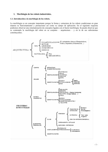
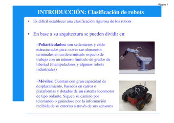
Rovables: Miniature On-Body Robots as Mobile WearablesArtem Dementyev1 , Hsin-Liu (Cindy) Kao1 , Inrak Choi2 , Deborah Ajilo3 , Maggie Xu2 ,Joseph A. Paradiso1 , Chris Schmandt1 , Sean Follmer22 Mechanical Engineering3 Mechanical EngineeringMedia LabMITStanford UniversityMITCambridge, MAStanford, CACambridge, MAartemd@media.mit.edu, cindykao@media.mit.edu, irchoi@stanford.edu, dmajilo@mit.edu,manqixu@stanford.edu, joep@media.mit.edu, geek@media.mit.edu, sfollmer@stanford.edu1ABSTRACTWe introduce Rovables, a miniature robot that can move freelyon unmodified clothing. The robots are held in place by magnetic wheels, and can climb vertically. The robots are untethered and have an onboard battery, microcontroller, andwireless communications. They also contain a low-power localization system that uses wheel encoders and IMU, allowingRovables to perform limited autonomous navigation on thebody. In the technical evaluations, we found that Rovablescan operate continuously for 45 minutes and can carry up to1.5N. We propose an interaction space for mobile on-bodydevices spanning sensing, actuation, and interfaces, and develop application scenarios in that space. Our applicationsinclude on-body sensing, modular displays, tactile feedbackand interactive clothing and jewelry.abcdACM Classification KeywordsH.5.m. Information Interfaces and Presentation (e.g. HCI):Miscellaneous.Author KeywordsOn-body robotics, mobile wearable technologyINTRODUCTIONWhat if wearable devices could move around the body? For example, fingernail-sized robots that could seamlessly assembleint a wristwatch or a nametag. Current wearable technologiesare immobile devices that are worn on the body, such as smartwatches (e.g. Pebble, Apple Watch), head-mounted displays(e.g. Google Glass), and fitness trackers (e.g. FitBit). Astechnology becomes smaller and more power efficient, it willmove closer to the body. Even now we are witnessing theappearance of sensor-enabled fabrics [19], and implanted [9]or on-skin electronics [25, 11]. However, this future does notaccommodate the possibility of dynamic devices. We envisionPermission to make digital or hard copies of all or part of this work for personal orclassroom use is granted without fee provided that copies are not made or distributedfor profit or commercial advantage and that copies bear this notice and the full citationon the first page. Copyrights for components of this work owned by others than ACMmust be honored. Abstracting with credit is permitted. To copy otherwise, or republish,to post on servers or to redistribute to lists, requires prior specific permission and/or afee. Request permissions from permissions@acm.org.UIST’16, October 16–October 19, 2016, Tokyo, Japan.Copyright 2016 ACM. ISBN 978-1-4503-4189-9/16/10ÂĚ 15.00DOI: http://dx.doi.org/10.1145/2984511.2984531Figure 1. a) Current Rovables prototype. Magnetic wheels provide anability to climb vertical clothing. The onboard electronics and sensorsprovide autonomous operation. b) Multiple Rovables climbing a shirt. c)In the future, Rovables could become fingernail sized. A swarm of themcan create an on-body interface or do distributed sensing. d) Rovableclimbing a vertical piece of fabric.that future wearable technology will move around the humanbody, and will react to its host and the environment.Most organisms from bacteria to trees (mobile seeds) haveways of locomotion, as finding a right location is crucial totheir survival. Although computationally powerful, most wearable technologies do not have such abilities. Lack of locomotion severely limits the abilities of on-body devices. Withlocomotion, wearable devices can become truly autonomous;they can perform self-maintenance, such as finding a port forcharging the battery. Locomotion can enable spatially-awaresensing. The location of the sensor is often central to its performance, and sensors will be able to find the optimal locationon their own. For example, for accurate heart rate monitoring,sensors need to be placed at the right locations around the
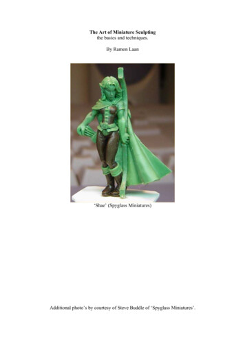
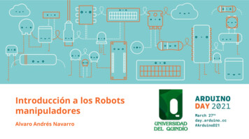
RovableSensingActuationMove clothingInterfacesDragging tactorLocation specificBest locationSelf maintenancePoint tactorModular displaysAnywhere inputHiding InterfacesTimed InterfacesFigure 2. Example interactions using Rovables. Gray squares represent one robot.heart. Furthermore, such wearable devices will have the ability to actuate their environment, such as moving somethingout of the way. Lastly, such devices will be able to appear anddisappear seamlessly. This idea fits the vision of ubiquitouscomputing [26], in which profound technologies disappearinto the background.and to sense location on the body. We see three importantcategories: actuation, sensing, and user interfaces. Althoughwe provide distinct categories, they are not clear-cut and canbe mixed together. Use cases from each category are providedin the applications section.In this paper, we start exploring the future where wearabledevices are dynamic and can move around the body. To realizethis concept we developed two core technologies. First, themagnet-based locomotion system, which allows the device tomove freely on clothing. Second, a navigation and controlsystem that allows the device to track its course and position.We believe in the future Rovables can become the size ofthe fingernail and completely autonomous. We are alreadywitnessing impressive advances in microrobotics such as theRobobee [28], a miniature flying robot.Tactile Display. Rovables can be used as a versatile tactiledisplay. The robots can be equipped with a vibration motoror a linear actuator that pokes the skin. The feedback can beprovided in two ways. First, the robot can move to a specificlocation and provide tactile feedback. Second, the robot canprovide tactile feedback by dragging the tactor across the skin.Skin drag effect has been shown to produce stronger feedbackthen only vibrations [10]The contributions of the paper are as follows:1. New paradigm of mobile on-body devices, and their possible interactions space.2. We implemented a novel platform, composed of miniaturerobots that can move on unmodified clothing. The robotsare held in place by neodymium magnet wheels grippingbetween the fabric. The robots are untethered with onboardpower, computation, and wireless communications.3. We developed algorithms and sensors to track and controlthe position of each robot, that allow limited autonomousoperation.4. We performed technical evaluation such as payload weight,battery life, and localization accuracy.5. We explore a range of application scenarios such as tactile feedback, body motion sensing, mobile jewelry, andwearable displays.INTERACTION SPACEIn this section, we will describe the design space and interaction potential of Rovables. Unique interactions can beachieved with the ability to move and act on the environment,ActuationActuating clothing. Rovables can act on external objects suchas clothing. The robots can attach themselves to clothing withhooks, and push/pull pieces of clothing. As a result, clothingcan be self-adaptable for both practical and aesthetic reasons.Self-maintenance. The robots can perform self-maintenance.If their battery is running low, Rovables can locate a charger.If the robots malfunction, they can detach themselves from thehost, when they sense a repair station.SensingRovables can provide an extension of Body Area Networks(BAN), a term describing wireless sensor nodes attached toa body to perform continuous health monitoring [14]. Manytypes of sensors require being in a specific location. With alarge number of sensors, it is cumbersome to place individualsensors in the right location. For example, to perform wholebody motion tracking with IMUs, 17 sensors have to be manually positioned in a specific orientation on the body. Mobilesensors can automatically position themselves in the right locations. Also, often it is not known in advance where the bestlocation is. Rovables can obtain data in multiple locations,and find the best one.User interfacesRovables can function as a physically-reconfigurable user interface. Robots can move to a location to provide both input
and output functionality on demand. Each robot can carry adisplay on the top, together creating a modular display. Therobots can assemble together to create a larger display or tochange its form factor. Such display can adapt based on thecircumstances. Besides output, the robots can be used foralways-available input, such as touch-screen and gesture sensing. Such input capabilities are now autonomously mobile andcan go where they are needed.The robots can hide and get out of the way of they are notneeded. For example by moving into a hidden pocket inside ajacket or by detaching from the body. Also, they can hide byserving a decorative function, such as jewelry. Also, Rovablescan be timed interfaces. In other words, programmed to havea routine and take different roles throughout the day. Forexample, sensing in the morning and display in the evening.This allows robots to move very slowly, so their movementsare not perceptible for the host.Example interactions throughout the dayTo better understand how the different interactions fit together,we provide example interactions throughout a day of an imaginary adult, Mary. Here we assume that Mary wears tens offingernail-sized autonomous robots.In the morning Mary goes to the gym. Rovables move toher limbs, to track all of her movements, and to the chest tomeasure respiration and heart rate. This allows collection ofextensive data for analysis and feedback. Next, Mary takes thesubway to work. To watch a movie, the robots assemble onher arm to create a display. This eliminates the need to haveother devices, such as smartphones. If it gets too hot the robotswill move Mary’s sleeves up. Once Mary gets to the office,the robots assemble into a name tag on her chest. Robots willgently tap Mary on the shoulder if she gets an important email.After work, Mary goes to a restaurant with friends. The robotswill form a decorative necklace and a matching bracelet. Afterthe restaurant, Mary decides to bicycle home after dark. Forsafety reasons, robots move to her back to make red stop lights,and to the front to illuminate the path. They will also tap Maryon left or right shoulders to indicate GPS directions. Once shegoes to sleep the robots will monitor the quality of her sleepand wake her up at the best moment. Throughout the day, therobots will collect extensive physiological data to learn habitsand for health diagnostics.DESIGN CONSIDERATIONSAt the core, the robot should be unobtrusive to the wearer. Toachieve that, we consider the following design criteria to beimportant:1. Small form-factor. The devices should be as small andas lightweight as possible. Since the device is close to thebody, smaller size and weight is less obtrusive for the humanhost. Furthermore, clothing has limited space for travel,especially places such as sleeves. The size should be limitedto 1.5cm x 1.5cm, the diameter of a small wristwatch.2. Navigation The robot should be able to track its positionson unmodified clothing. Such a system should not requireexternal aids, such as cameras. This will allow autonomousmovement on the host’s clothing, without disturbing orlimiting the wearer.3. Mobility The device should move freely vertically on unmodified clothing. Furthermore, it should be able to moveon loose and wrinkled clothing. The device should be ableto carry a payload, allowing it to actuate clothing or to carrysensors.4. Communications The device’s basic functionality shouldinclude wireless communications with external devices.This will allow coordination between multiple robots andinteraction with devices such as PCs and mobile phones.Communications between robots will enable more complexbehavior and tasks.5. Power As manually charging multiple robots can be timeconsuming, the robot should have an ability to charge itself.Also, the robot’s battery should last for at least 30 minutesof movement, and for 8 hours without movement. This willprovide enough time for the robot to perform any of thetasks that were proposed in the interaction space, and returnto the charger.6. Platform The system should be designed as a platform, soanybody can build and experiment with wearable robots.The system should be inexpensive to build, modular, andflexible enough to easily add more components and interfaces.PREVIOUS WORKOn-body robotics is a largely unexplored area. Though vertical climbing robots have been demonstrated in the roboticsfield, they are often limited to specific materials, and theyhave not spread into other fields such as Human-ComputerInteraction, due to specialized technologies. However, theavailability of low-power electronics and miniature gear motors enables broader explorations. We are not aware of anywork that explored free-moving on-body robots beyond movement mechanisms. Previous work can be categorized into threefields: First, climbing robots from the robotics field. Second,actuated interfaces and invisible interfaces in human-computerinteraction. Third, transforming clothing in fashion.Climbing robotsThe idea of vertical climbing has been explored in robotics.For example, Stickybot [12] mimics gecko by using adhesivefeet to climb vertical surfaces. Similarly, Waalbot [16] usesadhesive rotary legs to climb vertical surfaces. Rubbot [2] andClothbot [15] uses two wheels to grip into folds on clothing.CLASH [1] robot has six legs which can penetrate into clothto enable vertical adhesion. Although the work in roboticsdemonstrates the possibility of vertical climbing, it does notexplore applications. Also, the robots are not miniaturizedenough to explore on-body applications.Actuation in Human-Computer InteractionA few works in Human-Computer Interaction (HCI) exploredon-body robotics for various applications. The concept ofParasitic Mobility [13] illustrates sensor nodes that can jumpfrom one human host to another. Perhaps, the most closely
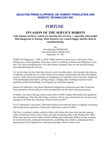
related work developed a mouse-like robot that moves on arail mounted on the arm [23]. In this early work, authors do alimited user study to explore how the participants feel aboutthe robot. The prototype is limited as it is bulky and can onlymove on a specially-designed rail. One intriguing concept [3]showed a quad-copter that can attach to the wrist, fly aroundto take pictures, and come back.A lot of work in HCI focuses on adding actuation to objectsand devices. For example, Pigmy [18] is a ring with moving eyes and mouth, used for storytelling applications. Onework developed a shape-changing mobile phone [7]. Otherworks demonstrated an approach for making shape-changingdevices using pneumatic actuation [5, 29], an array of servomotors [17] or shape-memory alloys [20]. In contrast, weare more concerned with mobility and creating interfaces ondemand.Invisible Interaction in Human-Computer InteractionsResearchers in HCI have explored the concept of invisible orre-configurable on-body interfaces that users can interact with.The work of Harrison [8] explored using projection to creategraphical touch-based interaction on the body. Others haveexplored using discrete or embedded sensing to sense gesturesacross the body for "invisible" interfaces [21]. These systemscannot provide tactile feedback and rely on a projection whichmay not work in all lighting conditions, or focus only on input.movement. Such motors are only 6mm in diameter and havehigh gear ratio. The gear motors were attached to neodymiummagnet wheels (9mm diameter). Next to the drive wheels,another set of neodymium magnet wheels was used to stabilizethe movement. Those wheels were connected by miniatureball bearings (4mm diameter), to reduce friction. Both sets ofwheels were covered with 1mm-thick Neoprene rubber tires toreduce slippage. On the other side of the fabric, a rod with twoneodymium wheels locked into the upper wheels. Becauseof magnetic attraction, the magnetic rod is moved with theupper wheels. This holds the robot in place, regardless of itsorientation. The body of the robot was 3D printed in one pieceusing Objet Eden260VS (Stratasys)Other works used different mechanisms for climbing, such asby pinching the fabric [15]. Although our approach requires amagnet on the back side, we picked it for simplicity and forease of miniaturization.a2.4GHzantennaareflective pattern2.6cmrubbermagnetic rodmotorFigure 3. Illustration of the magnetic drive system. a) The fabric is heldbetween the top two wheels and magnetic rod on the other side. All thewheels are circular neodymium magnets. The reflective pattern on thewheels is used for the infrared encoder. b) Underside view of the chassis,with the fabric, removed. Two motors are visible in this view.IMPLEMENTATIONIn this section, we will describe the mechanical and electricaldesign of Rovables. All the design files will be open sourcedat github.com/rovablesVertical-climbing magnetic drive2.6cm4.0 cmIR encodermotorFigure 4. Picture of the electronics and sensors. a) Top view. Customdesigned circuit board is visible on the top. Infrared encoders are placedon left and right wheels. The expansion port on the top is used to addmore functionality. b) Side view. As visible in this view, the battery issandwiched between the motors and the circuit board.HardwareThe system diagram is shown in Figure 6. To reduce the sizeand weight we made a custom 1mm-thick PCB (printed circuitboard), as shown in Figure 4. We added a 14-pin connector soshields can be added for more functionality (e.g. additionalsensors). We exploit this feature in the applications section.The main processor is ATmega328p (Atmel). The system ispowered by 100 mAh lithium polymer battery.bmagnetBatterybmicrocontrollerRobotics in clothing and fashionThe fashion industry has been captivated by the idea of clothing that can automatically adapt based on the environment.ZipperBot [27] is a motorized zipper that can automaticallyzip and unzip. In 2006 a fashion show featured clothing thattransform by using motors and pulleys [22]. The work inthis area is mostly task specific and does not conceptualize ageneralized platform.IMU expansion portThe magnetic-drive chassis is shown in Figure 3. We used two136:1 planetary gear motors (TGPP06-D-136, TT Motor) forFor radio communications with the base-station we used2.4GHz radio; nRF24L01 (Nordic Semiconductors). Wedecided to use a customwireless protocol versus standardrubbera rubber(Bluetooth,WiFi)b to allow control of multiple robots withoutlarge latencymotor while reducing power consumption. Furthermore,2.4GHz frequency allowed for a miniaturized antenna. Themotorbase-station contained the fabricsame nRF24L01 radio with extended range antenna. It also contained ATmega32u4 (Atmel)microcontroller to communication to PC over USB, and tocontrol the radio. We used a server-client architecture for communications. On the PC side, C based openFrameworkswas used to control Rovables, process and visualize data. Inthis configuration, the base-station is the server, and the robotsare the clients. The robots send the data to the server at 10Hzintervals. To prevent data collisions with multiple radios theretry period was randomized for each robot.
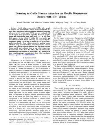
For orientation sensing, we used an MPU6050 (InvenSense)inertial measurement unit (IMU). It contains 3-axis gyroscopeand 3-axis accelerometer, and can calculate 3-D orientationon-board. To estimate the traveled distance and the speed, wedesigned incremental infrared optical encoders with GP2S60A(Sharp). The encoders work by measuring the changes in infrared reflectance of a disk with alternative white and blackstripes. The disk was printed on glossy poster paper and gluedon the wheels. To generate digital interrupts, the encoderswere connected through a Schmidt trigger. We didn’t use magnetic encoders because of interference from magnetic wheels.For IR proximity sensing four TSSP77P38 (Vishay) were used.The sensors were mounted on the removable display shield,which is further described in the applications section and Figure 11.Wireless ChargingBy putting an inductive coil (WR221230-36M8-G, TDK) onthe undercarriage, Rovables can charge wirelessly. The coil isshown in Figure 5. The coil is only 0.5 mm thick, so it does notinterfere with movements. The charging was done using 13.56MHz Qi wireless power standard. As a secondary purpose,the charger can serve as home, for the dead-reckoning system,described in the next section. When the device goes home itcan re-calibrate to reset the accumulated error.aprovide an initial exploration. In this section, we discuss howwe implemented the limited autonomous operation, and howit should work ideally.LocalizationFor Rovables to move autonomously around clothing, theirposition has to be tracked. Localization is difficult for thefollowing reasons. First, fabric and cloth have complex anduneven 3D shapes. Second, the localization system has tofit inside the small robot and use little energy. Third, itshould be self-contained, without big external components(e.g., cameras) or wires, and work on unmodified clothing.These challenges exclude off-the-shelf tracking systems, suchas magnetic tracking (e.g., Polhemus) and infrared cameratracking (e.g., OptiTrack) systems. Localization with Bluetooth [24] or other radio signals appear more attractive as theycan be integrated into the base station. Unfortunately, theyhave limited accuracy (12.5cm wavelength for 2.4GHz) andhigh power consumption.abbyLocation nθh3Figure 5. The wireless charging system. a) The receiver coil is mountedon the underside of the chassis. b) The yellow transmitter coil can betaped on the back side of the fabric. The Rovable is parked on the coil,as seen by its magnetic rod. The main body is on the other side of thefabric.x2 3h2x1 2θ2 y2h1θ1y1Location 1MotorMotorControllerMotorSchmidt TriggerSchmidt tation2.4 GHzradioIMUExpansionSlotSensors,display, etcFigure 6. System diagram. The parts inside the red dashed lines are onthe main board.AUTONOMOUS NAVIGATIONRovables need to have the ability for autonomous navigation.Accurate autonomous 3D navigation of robots on complexsurfaces is still an open question in robotics [4], and our effortshxFigure 7. Localization system. a) Localization of three Rovables simultaneously. The square pattern on the fabric was not used for actual localization, but to provide visual aid during for the developers. b) Thegraphical representation of the dead-reckoning algorithm. The locationis determined by previous location, yaw angle, and the traveled distance.We used dead-reckoning for localization. Dead-reckoning isa position estimation algorithm, where current location is determined from the previous position. Our system uses threesensors: encoders on both motors allow distance and angledata, IMU provides relative orientation, and IR beacon provides a starting reference point for dead-reckoning. With fourIR proximity sensors on the robot, the IR beacon could belocalized, even with a large dead-reckoning drift. We couldnot use a magnetometer, because of interference from magnetic wheels. Our current implementation works in planarsurfaces, but not accurately in full 3D. With more memory and
computational power, we believe our approach will work onany complex clothing.much extra weight it can carry, which enables interactionssuch as actuating clothing.The dead-reckoning algorithm works as following. qn is theyaw angle. The distance traveled is h. The scaling factor qwas used for conversion of encoder data onto centimeters.The force of attraction between wheels and the magnetic rodmostly depends on the thickness of clothing, as shown inFigure 8 (top). The measurements indicate the minimum forceneeded to pull wheels and magnet rod apart. Generally, thickerclothing has lower attraction forces. The maximum force is4.2N when there is no clothing in between. Measurementswere done with Series 5 force gauge (Mark-10).xn xn1 qh cos(qn )(1)yn yn1 qh sin(qn )(2)Path planningThe computer (server) does not control the movement of therobots directly. It transmits the commands for the robots toaccomplish. This is because the radio communication can befaulty and unpredictable. The server also keeps tracks of theoverall map and where robots are in relation to each other.There are three basic commands: (1) move specified distanceforward, (2) move specified distance backward and (3) turnto a specific angle. Using these three movements a complexpath can be followed. Each of the three movements was executed with different PID (proportional-integral-derivative)controllers. Without the PID controller, the robot would notfollow a straight path, as the fabric surface is not even, andmotors are not symmetrical. The IMU yaw angle was usedto correct the course. Also, yaw angle was used to controlturning.Given a certain power supply, the climbing force of Rovabledepends both on the thickness and fabric of clothing. Thethickness is dominant but for some materials like linen, theclimbing force does not follow the trend because of low friction coefficient. Figure 8 (bottom) reflects the force with themotor running at 3.7V DC on a horizontal plane. Its payloadwhen going vertically will be the measured force minus itsown weight, which is 0.2N.As shown in Figure 7, we made a fabric test-bed and corresponding software for testing the path planning and navigation.The test-bed was mounted vertically, to reflect actual usage.Fully autonomous operationIn this section, we will describe how the autonomous systemshould ideally function. A mobile phone or another wirelessdevice can act as a server and base station for Rovables. Theuser would scan the garment’s barcode to find and load the3D model of the garment into the server. The 3D model isnecessary for localization. Next, the user would attach a basestation to the backside of the fabric. The base station has twopurposes: charging and dead-reckoning starting point. Thiscan be as simple as putting a smartphone into a pocket. Manyphones have inductive coils and thus can serve as a chargingbase station. Lastly, a small IR beacon would be pinned ontop of the base station. This will allow the robots to easily findthe starting point and the charger. Finally, the robots wouldbe placed on the clothing. They can be placed anywhere, asthey can automatically find the IR beacon. Throughout theday robots will need to go back to the base station, to rechargeand reset dead-reckoning errors. No intervention from theuser would be required. The robots would only move whenthe user is not moving. This can be easily detected by IMUs.During body movements the clothing can have unpredictabledeformation, thus confusing the navigation system.TECHNICAL CONSIDERATIONSPayloads and forcesIt is important to quantify the force that Rovable can pull andhow it is influenced by the type of fabric. This determines howFigure 8. Measurement of attraction (top) and climbing forces (bottom)on different fabrics.Power consumption and battery lifeThe maximum power consumption is 120.4mA (398mW),which allows for a battery life of 45 minutes with a 100mAhbattery. This is the power required with motors on and allsystems on (IMU, wireless, encoders). Motors use the most energy: 91.9mA. The encoder’s infrared LEDs consume 20mA.The rest of the electronics consume just under 8.5mA.Assuming that all systems will not be active all the time, thebattery life could be greatly extended. For example, the opticalencoders can be disabled when motors are not running. Thedevice can wirelessly stream data for 11.8 hours if the motorsand encoders are off.Wireless communicationsEach Rovable transmits and requests a 32-byte packet every100ms, providing a data rate of 0.32Kb/sec. The network supports up to 3 robots reliably. With more robots, data collisionsbecome more frequent and cause errors and large latency. Inthe future, collisions can be avoided with synchronization andby allocating transmissions into slots.
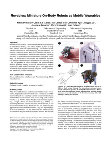
We developed a kinematic chain model of the human bodyusing openFrameworks library [6]. The data from IMUs wasfed into inverse kinematics equations to track the positions ofthe joints.03Y distance (cm)SensorsCamera6a9b121518051015202530X distance (cm)Figure 9. Localization accuracy on a 2D fabric. Comparison of a camera(ground truth) and on-board sensors for localization of one path.Localization accuracyAs shown in Figure 9, we tested localization accuracy using onboard sensors and a reference camera. The path wasrecorded on a calibration fabric, which is shown in Figure 7.The robot’s movement from the camera was manually analyzed and was assumed to be the ground truth. We found thatour localization algorithm has a mean error of 1.95cm and astandard deviation of 1.03 cm. As Figure 9 shows there is anerror is both linear distance (encoders) and yaw angle (IMU).The possible sources of error include limited resolution ofthe encoder (2.4mm) and wheel slippage. Furthermore, theIMU had a yaw angle error of about 6.4 degrees, as measuredwith reference angles as the ground truth. The IMU did notexperience drift, as on-chip algorithms corrected for it.The accuracy can be improved by using Kalman filter, whichis commonly employed in robotic localization. Kalman filtercombines the data from multiple sensors (encoders, IMU,motor commands) to provide a better location estimate. Ourcurrent system does not have enough memory to run Kalmanfilter in real-time.APPLICATIONSIn this section, we will introduce the potential applications ofmobile on-body interfaces. The applications were created toexplore the design space, as proposed in the interaction spacesection and Figure 2.Body motion trackingCore interactions: Location-specific sensing. Motion captureis used to record the movement of people or objects. Motioncapture has many applications such as in medicine, sports,and gaming. Most of
1. New paradigm of mobile on-body devices, and their possi-ble interactions space. 2. We implemented a novel platform, composed of miniature robots that can move on unmodified clothing. The robots are held in place by neodymium magnet wheels gripping between the fabric. The robots are untethered with onboard power, computation, and wireless .