Transcription
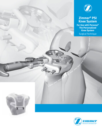
Surgical TechniquePhoenixTibial Nail SystemFeaturingCoreLock Technology Each nail features CoreLock Technology, a preassembled,embedded locking mechanism for locking all proximal obliquescrews, which can also be used to internally mechanicallycompress up to 5mm for a variety of tibial fractures Distally, the tibial nail offers an exceptionally low distal aspectof 4.5mm from the center of the most distal screw hole to thenail tip and 10mm from the center of the second most distalscrew hole from the cluster to the nail tip for treatment ofvery distal fractures
ContentsIntroduction. Page 1Indications and Contraindications. Page 2Design Features. Page 3Surgical Technique . Page 6Product Ordering Information . Page 31
IntroductionPhoenix Tibial Nail SystemThe Phoenix Tibial Nail System is composed of titanium alloyThis material represents the surgical technique utilized by and features CoreLock Technology that offers a preassembled,Michael S. Sirkin, M.D., Cory A. Collinge, M.D. and Kenneth J.embedded locking mechanism for locking all proximal obliqueKoval, MD. Biomet does not practice medicine. The treatingscrews, which can also be used to internally mechanicallysurgeon is responsible for determining the appropriate treatment,compress up to 5mm for a variety of tibial fractures. Distally, thetechnique(s), and product(s) for each individual patient.tibial nail offers an exceptionally low distal aspect of 4.5mm fromthe center of the most distal screw hole to the nail tip and 10mmfrom the center of the second most distal screw hole of the clusterto the nail tip for treatment of very distal fractures.The tibial nail is universal and available in outer diameters of7.5mm, 9mm, 10.5mm, 12mm and 13.5mm for applicationsin a wide variety of patients in lengths of 240mm-420mm, in10mm increments. Additionally, the system features a strong,lightweight Radiolucent Targeting Arm that permits radiographicvisualization in multiple planes. With its easy to use color-codedinstrumentation conveniently contained in a single tray and itsinnovative implant design, the Phoenix Tibial Nail System isdesigned to address both patient and surgeon needs.1
IndicationsINDICATIONSCONTRAINDICATIONSPhoenix Tibial Nail SystemThe Phoenix Tibial Nail System is indicated for alignment,stabilization, and fixation of fractures caused by trauma ordisease, and the fixation of long bones that have been surgicallyprepared (osteotomy) for correction of deformity and forarthrodesis.1. Infection.2. Patient conditions including blood supply limitations, andinsufficient quantity or quality of bone.3. Patients with mental or neurologic conditions who areunwilling or incapable of following postoperative careinstructions.4. Foreign body sensitivity. Where material sensitivity issuspected, testing is to be completed prior to implantation ofthe device.2
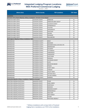
Design Features9 mmProximal ObliqueScrew Holes49mmDynamic/CompressionSlot10mmStatic HoleOBL90 OBL45 45 M/LM/L45 45 OBLOBL90 15.6mm10mm1.8mm*4.5mm*2.4mm for 7.5mm nail only3 DistalBend51mm(Distal Bend Location)NOTE:Views are not to scale and should be used for reference only.3
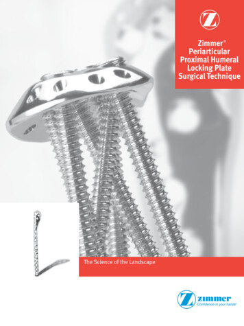
Design Features (Continued)CoreLock TechnologyInnovation made simple and elegant through deployment of thepreassembled, embedded setscrew/locking mechanism.Ability to lock proximal oblique screws to nail via preassembled,embedded setscrew/locking mechanism.5mm of internal mechanical compression via embeddedsetscrew/locking mechanism.7.5mm9mm10.5mm12mm13.5mmNail diameters offered:7.5mm, 9mm, 10.5mm, 12mm and 13.5mmOffered in lengths ranging from 240mm-420mm (10mmincrements)Proximal diameter for 7.5mm, 9mm and 10.5mm nail is 11mmSince the holes within the embedded setscrew are grooved,proximal screw removal can be achieved without disengaging theProximal diameter for 12mm nail is 12mmProximal diameter for 13.5mm nail is 13.5mmembedded setscrew.4
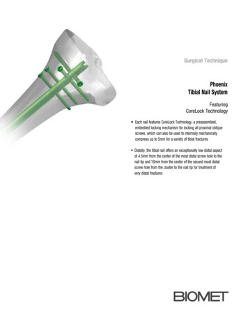
Double-Lead Thread Screws- Composed of Titanium Alloy- Features a double-lead thread design for quick insertion- Self-tapping tip- Interior of 4mm and 5mm cortical screw head is threadedfor secure retention to inserter- Threads are close to screw head and screw tip for betterbicortical purchase4mm Double-Lead Thread Screw- Used distally for locking 7.5mm nail only- Color-coded gold4mm Screw Lengths:20mm – 58mm(Available in 2mm increments)3.5mm Inserter Connector(Long & Short) retains headof screwInterior of screw head isthreaded for retention toinserterEnd Caps3.5mm Inserter Connector retains head of end capto facilitate easier insertion0mm5mm10mm15mm20mm5mm Double-Lead Thread Screw- Utilized for proximal locking all nail sizes- Used distally for locking 9mm, 10.5mmand 12mm nail sizes- Color-coded light green5mm Screw Lengths:20mm – 60mm(Available in 2mm increments)65mm – 110mm(Available in 5mm increments)5
Surgical TechniqueStep 1. Preoperative PlanningStep 2. Patient Positioning And PreparationSuccessful nailing of extreme distal tibia fractures is dependentThe patient is placed in a supine position on a radiolucentupon careful preoperative planning and patient evaluation.operating table, preferably one without metal sides for easeof imaging. Flex the knee 90 or greater over a knee triangleTo fully understand the fracture pattern, a complete radiographicor several rolled towels to provide access for adequate tissueevaluation of the entire tibia must be obtained. For those fracturesclearance of instruments.within 4cm of the physeal scar, formal ankle radiographs arenecessary to accurately assess the bone available for distalThe affected extremity should be prepped and draped free. Alocking. Careful scrutiny is mandatory, in order to delineate thethigh tourniquet may be used, but should not be left inflatedpresence or absence of any intra-articular pathology. Preoperativewhile intramedullary reaming is performed. Alternatively, aplanning with the use of implant templates can be helpful totraction table or femoral distractor can be used to obtain fractureassess whether distal locking is possible.reduction and maintain length while the nailing is performed.If grade IV comminution is present, radiographs of thecontralateral side will be necessary to help obtain the correctlength of the injured extremity. Alternatively, the contralateralside can be measured with the C-arm intraoperatively, prior toprepping and draping, using a radiopaque ruler and fluoroscopy.This will allow for the appropriate length nail to be chosen toaccurately restore the length of the fractured tibia.6
Step 3. Surgical ExposureA sagittal midline incision, centered over the patellar tendon,is made from the center of the patella to the top of the tibialplateau. The patellar tendon should be exposed to the level of theparatendon. Either a lateral or medial parapatellar approach isperformed, but the knee joint should not be entered. The patellafat pad should only be cleared anteriorly to permit entry for properportal placement.Step 4. Entry PointA 3.2mm x 460mm Entry Guide Wire (Catalog #27914) is placedjust distal to the articular margin, as viewed on the lateralradiograph. On an A/P image, the entrance portal will be justmedial to the lateral tibial eminence or just lateral to the midline.This position decreases risk of injury to the menisci, articularcartilage and ACL. Confirm placement of the Guide Wire using theC-arm image.9 ML7
Surgical Technique (Continued)Step 5. Opening The Medullary CanalAlternatively, a Curved Cannulated Awl (Catalog #41026) attachedto a Modular T-Handle, Non-Ratcheting (Catalog #29407) can bePlace the Working Channel Soft Tissue Sleeve (Catalog #41029)used to obtain the entrance portal.and the 11.5mm One-Step Reamer (Catalog #41009) over theGuide Wire to enlarge the entry site and drill until entering thecanal.11.5mmDiameterFor protection of the Modular T-Handle, Non-Ratcheting duringinsertion of the Curved Cannulated Awl, use of the Impactor Cap(Catalog #14-441047) is recommended.8
Step 6. Fracture Reduction And Guide Wire PlacementFracture reduction is performed manually, with use of an imageintensifier to aide with positioning. If the canal is to be reamed,a 2.6mm x 80cm Bead Tip Guide Wire (14-410002) is insertedthrough the opening in the proximal tibia and advanced to thelevel of the fracture. Images are checked as the Guide Wire ispassed across the fracture site. An A/P and lateral image shouldconfirm an intramedullary position of the Guide Wire in thecenter of the distal fragment in both planes. To help facilitateGuide Wire passage through the fracture site, the Keyless ChuckT-Handle (Catalog #14-442078) may be used. The Guide Wiremay be gently impacted into the distal metaphysis to the level ofthe physeal scar to prevent accidental removal of the guide wireduring reaming.9
Surgical Technique (Continued)In the case of a non-union, where the path to the canal isblocked and unlikely to advance a guide wire or entry reameracross the fracture site, a Pseudarthrosis Pin Straight (Catalog#14-442073) or Curved (Catalog #14-442074) may be usedto create an opening for the passage of a guide wire for canalreaming.5mmIn the event of a displaced fracture, the 8.5mm Fracture Reducer(Bowed) (Catalog #14-442068) may be used to facilitate GuideWire insertion through the fracture site.10
Step 7. Determining Nail LengthTo measure nail length, a direct reading can be made at thejuncture of the two tubes. The nail should be countersunk toThe Telescoping Nail Measuring Gauge (Catalog #14-440047)prevent any impingement. The selected nail should be at leastis placed over the 2.6mm Bead Tip Guide Wire, until it rests1cm shorter than the measured medullary canal to permiton the anterior cortex. The nail should come to rest in thecountersinking of the proximal end of the nail.distal metaphysis and can be inserted as distal as the physealscar. Choose the appropriate nail on this basis. With the GuideAlternatively, either a second Guide Wire of equal length may beWire resting at the desired distal level, the telescoping tube isused to measure the length of the medullary canal or use of aextended to the end of the Guide Wire.Medullary Canal and Length Estimator (Catalog #14-442075) maybe used to determine nail diameter and length.11
Surgical Technique (Continued)Step 8. Intramedullary ReamingUpon attaching the 8mm diameter Modular Reamer Head tothe Flexible Nitinol Reamer Shaft (40cm-Catalog #27958 or52cm-Catalog #27940), begin reaming over the Bead Tip GuideWire in 1mm increments until cortical chatter occurs and then in0.5mm increments. It is recommended that the surgeon ream to1mm greater than the diameter of the nail to be inserted.During medullary canal reaming, the Wire Pusher (CatalogReamer headdiameters availablefrom 8mm to 14.5mm(0.5mm increments)#41027) can be used to help retain the 2.6mm Bead Tip GuideWire during reamer extraction.NOTE: The 8mm reamerhead is the only forwardcutting reamer head; allothers are side-cutting.NOTE: Since the 2.6mm Bead Tip Guide Wire (Catalog #14-410002)will pass through all Phoenix Tibial Nail diameter cannulas, anexchange technique is not required.NOTE: Wire Pusherfeatures multiple bores.12
Step 9. Nail AssemblyNOTE: To ensure accurate proximal targeting, attach the TibialNail Targeting Arm (Catalog #41000) to the Driver Handle andAttach the Driver Handle (Catalog #41018) to the proximal aspectinsert the Soft Tissue Guide, Drill Sleeve and 4.3mm Calibratedof the tibial nail, ensure the slope is anterior and the three tangsDrill Bit through the associated arm slot to ascertain accuracy.on the underside of the Driver Handle engage with the three slotsUpon confirming accurate trajectories, remove the Targeting Armof the nail. Place the Connecting Bolt (Catalog #41002) into theand guides, if desired.Driver Handle and proceed to thread into the nail and secureusing a 5mm Connecting Bolt Inserter (Catalog #41003) attachedto the Modular T-Handle, Non-Ratcheting (Catalog #29407).IncorrectDriver Handlenose shownfully seatedto the nail13
Surgical Technique (Continued)Step 10. Nail InsertionThe tibial nail is inserted manually over the Bead Tip Guide Wireand advanced into the medullary canal. The fracture should beadequately reduced and out to length during insertion of the nailand should be monitored with the image intensifier. The Bead TipGuide Wire is removed after the nail passes the fracture site. Thenail can be countersunk to the level indicated by the groove onthe driver nose. Final nail positioning should be checked in bothA/P and lateral views to ensure proper alignment.If a Slotted Mallet (Catalog #14-442053) is desired to seat thenail into the canal, thread the Slap Hammer Adapter (Catalog#41001) into the Driver Handle and attach the Slap Hammer Shaft(Catalog #29448). To avoid nail misalignment, do not strike theDriver Handle directly.NOTE: It is recommended to only attach the Targeting Arm to theDriver Handle once the tibial nail has been completely seated intothe canal, to avoid potential loosening.20mm15mm29mm10mm5mmNOTE: Grooves on the Driver Handle nose help indicate depthwhen countersinking.14
Step 11. Determining Screw Length And Screw InsertionDetermining the length of the appropriate screw size for distalDetermining the appropriate 5mm screw length for proximallocking can be achieved by using a Screw Depth Gauge - Extralocking can be achieved by using a Screw Depth Gauge - ExtraShort (Catalog #14-442082) or overlay the 4.3mm x 152mmLong (Catalog #14-442081) or the appropriate screw length isShort Drill Bit (Catalog #27984) with the Short 4.3mm Drillmeasured off the 4.3mm Calibrated Drill Bit, at the end of theMeasuring Sleeve (Catalog #14-442076). Measurement is readDrill Sleeveat the end of the drill bit.NOTE: The 4mm screws are used distally with the7.5mm nail only.15
Surgical Technique (Continued)Screw InsertionWhen inserting distal screws, place the 3.5mm Inserter Connector,Short (Catalog #14-441045) through the cannula of either theModular T-Handle, Non-Ratcheting (Catalog #29407) or ModularAfter confirming the screw is retained to the insertion device,proceed with inserting the screw into bone and continue placingadditional screws as needed.Straight Handle, Ratcheting (Catalog #29408) and connect the3.5mm Inserter, Short (Catalog #14-441046).NOTE: When locking very distal screws, an attempt should bemade to countersink slightly, but not through the near cortex.When inserting proximal screws, place the 3.5mm InserterConnector, Long (Catalog #14-441043) through the cannula ofeither the Modular T-Handle, Non-Ratcheting (Catalog #29407) orModular Straight Handle, Ratcheting (Catalog #29408) and connectthe 3.5mm Inserter, Long (Catalog #14-441044).During proximal screw insertion, the line mark on the 3.5mmInserter, Long indicates when the screw head is fully seated(Ensure the Soft Tissue Sleeve is firmly against bone).Attach the appropriate screw to the threaded hex tip of theInserter Connector (Short or Long) and turn the knob in aclockwise fashion.NOTE: For final tightening 4mm screws and 5mm screws, the3.5mm Solid Inserter-Long (Catalog #14-441051) or the 3.5mmSolid Inserter-Short (Catalog #14-441052) should be used.16
Step 12. Targeting Arm AssemblyAssemble the Tibial Nail Targeting Arm (Catalog #41000) tothe Driver Handle and secure with the Thumb Screw (Catalog#41023).17
Surgical Technique (Continued)Step 13a. Proximal Locking - Static ScrewsAssemble the Trocar (Catalog #41006) to the Drill Sleeve (CatalogInsert the 4.3mm Calibrated Drill Bit (Catalog #41010) through#41005) and insert through the Soft Tissue Sleeve (Catalogthe Drill Sleeve to perforate the medial cortex, pass through#41004) through the Static hole (Dynamic Compression Slot) ofthe nail and perforate the lateral cortex. With the Drill Sleevethe Targeting Arm. Advance to the bone to determine and markassembly held firmly against the medial cortex, the appropriatethe entry point. Remove the Trocar and advance the assembly toscrew length is measured off the Calibrated Drill Bit, at the end ofthe near cortex.the Drill Sleeve. Alternatively, a Screw Depth Gauge (Extra Long)(Catalog #14-442081) may be used to determine or verify theDynamic Compression Slotlength of the screw.NOTE: All nail diameters utilize 5mm screws proximally.Static18
Step 13a. Proximal Locking - Static Screws (Continued)The Drill Sleeve is removed and the appropriate 5mm screwis inserted through the Soft Tissue Sleeve (reference pg. 16for insertion detail). Ensure position of screw with radiographicvisualization. Be sure not to exceed more than 2mm in the farcortex.If desired, the Static screw can be locked with the preassembled,embedded setscrew/locking mechanism. Insert the 4mm HexDriver (Catalog #41024) through the Driver Handle, into theproximal aspect of the nail and turn in a clockwise motion.19
Surgical Technique (Continued)Step 13a. Proximal Locking - Static Screws (Continued)StaticAn additional screw can be inserted in a similar fashion throughthe Static hole of the Targeting Arm (reference pg. 16 forinsertion detail).To remove the targeting assembly, insert the 5mm ConnectingBolt Inserter through the Driver Handle to engage the connectingbolt and turn counterclockwise to release attachment from thenail.20
Step 13b. Proximal Locking - Oblique ScrewsThe Drill Sleeve is removed and the appropriate 5mm screwis inserted through the Soft Tissue Sleeve (reference pg. 16for insertion detail). Ensure position of screw with radiographicvisualization. Be sure not to exceed more than 2mm in the farcortex.Assemble the Trocar (Catalog #41006) to the Drill Sleeve (Catalog#41005) and insert through the Soft Tissue Sleeve (CatalogRepeat this procedure for insertion of the second oblique screw.#41004) through either the Distal Oblique or the Proximal Obliquehole of the Targeting Arm. Advance to the bone to determineand mark the entry point. Remove the Trocar and advance theassembly to the near cortex.Insert the 4.3mm Calibrated Drill Bit (Catalog #41010) throughthe Drill Sleeve to perforate the medial cortex, pass throughthe nail and perforate the lateral cortex. With the Drill Sleeveassembly held firmly against the medial cortex, the appropriatescrew length is measured off the Calibrated Drill Bit, at the end ofthe Drill Sleeve. Alternatively, a Screw Depth Gauge (Extra Long)(Catalog #14-442081) may be used to determine or verify thelength of the screw.NOTE: All nail diameters utilize 5mm screws proximally.21
Surgical Technique (Continued)Step 13b. Proximal Locking - Oblique Screws (Continued)To remove the targeting assembly, insert the 5mm ConnectingBolt Inserter through the Driver Handle to engage the connectingbolt and turn counterclockwise to release attachment from thenail.When insertion of the proximal oblique screws are completed,insert the 4mm Hex Driver through the Driver Handle into theproximal aspect of the nail and turn in a clockwise motion to lockthe oblique screws with the preassembled, embedded setscrew/locking mechanism. When complete, remove the hex driver.22
Step 13c. Proximal Locking - Compression (Optional)Dynamic Compression SlotDynamicAssemble the Trocar (Catalog #41006) to the Drill Sleeve (Catalog#41005) and insert through the Soft Tissue Sleeve (Catalog#41004) through the Dynamic hole (Dynamic Compression Slot)of the Targeting Arm. Advance to the bone to determine and markthe entry point. Remove the Trocar and advance the assembly tothe near cortex.The Phoenix Tibial Nail offers a preassembled, embeddedsetscrew/locking mechanism that can provide up to 5mm ofcompression.NOTE: Mechanical compression may only be achieved throughthe Dynamic hole and deployment of the preassembled,NOTE: If compression is desired, first ensure distal lockingembedded setscrew/locking mechanism.has been completed. Prior to compressing, remove the sleeveassembly from bone.23
Surgical Technique (Continued)Step 13c. Proximal Locking - Compression (Optional)ContinuedInsert the 4.3mm Calibrated Drill Bit (Catalog #41010) throughthe Drill Sleeve to perforate the medial cortex, pass throughthe nail and perforate the lateral cortex. With the Drill Sleeveassembly held firmly against the medial cortex, the appropriatescrew length is measured off the Calibrated Drill Bit, at the end ofthe Drill Sleeve. Alternatively, a Screw Depth Gauge (Extra Long)(Catalog #14-442081) may be used to determine or verify thelength of the screw.The Drill Sleeve is removed and the appropriate 5mm screwis inserted through the Soft Tissue Sleeve (reference pg. 16for insertion detail). Ensure position of screw with radiographicvisualization. Be sure not to exceed more than 2mm in the farcortex.NOTE: All nail diameters utilize 5mm screws proximally.24
Step 13c. Proximal Locking - Compression (Optional)ContinuedIf using the preassembled setscrew for compression is desired,insert the 4mm Hex Driver (Catalog #41024) through theDriver Handle, into the proximal aspect of the nail and turnin a clockwise motion. Monitor screw position and fracturecompression under radiographic visualization.Alternatively, a backstroke technique can be employed forcompressing the fracture by using the Slotted Mallet in a reversemanner under radiographic visualization monitoring.25
Surgical Technique (Continued)Step 13c. Proximal Locking - Compression (Optional)ContinuedStaticAfter desired compression is achieved, repeat screw insertionthrough the Static hole to support the achieved compression.Upon screw insertion into the Static hole, use the 4mm HexDriver to reverse the preassembled setscrew (counterclockwise)until it stops against the Connecting Bolt. This will ensure correctpositioning of the preassembled setscrew for locking the proximaloblique screws, if desired.26
Step 13c. Proximal Locking - Compression (Optional)ContinuedTo remove the targeting assembly, insert the 5mm ConnectingBolt Inserter through the Driver Handle to engage the connectingbolt and turn counterclockwise to release attachment from thenail.When insertion of the proximal oblique screws are completed,insert the 4mm Hex Driver through the Driver Handle into theproximal aspect of the nail and turn in a clockwise motion to lockthe oblique screws with the preassembled, embedded setscrew/locking mechanism. When complete, remove the hex driver.27
IntroductionStep 14. Distal LockingVerify the depth of the nail distally in both A/P and lateral views.The Phoenix Tibial Nail may be locked distally with screws inboth the sagittal and frontal planes. Distal A/P locking allows forplacement of perpendicular screws for a more secure fixation ofthe distal fragment.When treating distal third fractures, ensure at a minimum, twodistal locking screws are used below the fracture site.A/P ViewNOTE: When locking from anterior to posterior all instrumentsM/L Viewplaced to the bone should be done medial to the tibialis anteriortendon. The tendon should be retracted laterally to allow safeplacement of the locking screw.Distal locking may be accomplished using a freehand techniqueor by using the Biomet Radiolucent Targeting Device. Theimage intensifier is aligned with the more distal hole in the nail,such that the hole appears as a perfect circle. A knife blade isplaced on the skin, with the incision point verified on the imageintensifier, and a 1cm incision is made over the hole in the nail.The tip of the drill bit appears as a solid circle in the center of thescrew hole. Proceed to drill through both cortices. The position ofthe drill bit is confirmed on the image intensifier in both the A/Pand Lateral planes, before it is withdrawn. Additional screw holesare drilled in a similar fashion.Perfect CircleNOTE: Distally, a 3.2mm drill bit is used for 4mm screws with the7.5mm nails only and a 4.3mm drill bit is used for 5mm screwswith 9mm or larger nails.IncorrectNOTE: For final tightening 4mm screws and 5mm screws, the3.5mm Solid Inserter-Long (Catalog #14-441051) or the 3.5mmSolid Inserter-Short (Catalog #14-441052) should be used.28
End Cap InsertionIf desired, one of five different profile end caps ranging from 0mmto 20mm (available in 5mm increments) can be inserted into theproximal end of the Phoenix Tibial Nail to prevent bony in-growth.For insertion, thread the end cap to the insertion device, in similarfashion for screw insertion (as referenced on pg. 16).0mm5mm10mm15mm20mmNOTE: For final tightening end caps, the 3.5mm Solid InserterLong (Catalog #14-441051) or the 3.5mm Solid Inserter-Short(Catalog #14-441052) should be used.29
Surgical Technique (Continued)Nail RemovalRemove the end cap if implanted and all but one of the lockingscrews with the 3.5mm Inserter Connector. It is important to leaveone screw in the nail to prevent nail rotation when connectingthe nail extractor to the nail. Alternatively, if all screws have beenremoved a 4.3mm Drill Bit can be placed through any of theremoved screw holes. If needed, the 3.5mm Hex Screw Extractor*(Catalog #14-442084) may be used to remove either a 4mm or5mm screw.Insert a Guide Wire into the top of the nail to help guide theextractor to the proximal portion of the nail. Attach the 3/4”Driver (Catalog #14-442066) to the Nail Extractor Tap* (Catalog#14-441048) and thread the assembly into the top of the nail. Atight interference fit should be achieved. The extractor is meantto cross-thread into the proximal portion of the nail. Thread theSlap Hammer Shaft (Catalog #29448) into the Nail Extractor Tapand remove the remaining screw or drill bit. Extract the nail with abackslapping motion using the Slotted Mallet.NOTE: Since the holes within the embedded setscrew are grooved,proximal screw removal can be achieved without disengaging theembedded setscrew.*Available sterile packed30
Product Ordering Information7.5mm Tibial Nails9mm Tibial Nails 024Tibial Nail, 7.5mm x 240mm40337Tibial Nail, 9mm x 370mm40025Tibial Nail, 7.5mm x 250mm40338Tibial Nail, 9mm x 380mm40026Tibial Nail, 7.5mm x 260mm40339Tibial Nail, 9mm x 390mm40027Tibial Nail, 7.5mm x 270mm40340Tibial Nail, 9mm x 400mm40028Tibial Nail, 7.5mm x 280mm40341Tibial Nail, 9mm x 410mm40029Tibial Nail, 7.5mm x 290mm40342Tibial Nail, 9mm x 420mm40030Tibial Nail, 7.5mm x 300mm10.5mm Tibial Nails40031Tibial Nail, 7.5mm x 310mmCatalog#Description40032Tibial Nail, 7.5mm x 320mm40624Tibial Nail, 10.5mm x 240mm40033Tibial Nail, 7.5mm x 330mm40625Tibial Nail, 10.5mm x 250mm40034Tibial Nail, 7.5mm x 340mm40626Tibial Nail, 10.5mm x 260mm40035Tibial Nail, 7.5mm x 350mm40627Tibial Nail, 10.5mm x 270mm40036Tibial Nail, 7.5mm x 360mm40628Tibial Nail, 10.5mm x 280mm40037Tibial Nail, 7.5mm x 370mm40629Tibial Nail, 10.5mm x 290mm40038Tibial Nail, 7.5mm x 380mm40630Tibial Nail, 10.5mm x 300mm40039Tibial Nail, 7.5mm x 390mm40631Tibial Nail, 10.5mm x 310mm40040Tibial Nail, 7.5mm x 400mm40632Tibial Nail, 10.5mm x 320mm40041Tibial Nail, 7.5mm x 410mm40633Tibial Nail, 10.5mm x 330mm40042Tibial Nail, 7.5mm x 420mm40634Tibial Nail, 10.5mm x 340mm9mm Tibial Nails40635Tibial Nail, 10.5mm x 350mmCatalog#Description40636Tibial Nail, 10.5mm x 360mm40324Tibial Nail, 9mm x 240mm40637Tibial Nail, 10.5mm x 370mm40325Tibial Nail, 9mm x 250mm40638Tibial Nail, 10.5mm x 380mm40326Tibial Nail, 9mm x 260mm40639Tibial Nail, 10.5mm x 390mm40327Tibial Nail, 9mm x 270mm40640Tibial Nail, 10.5mm x 400mm40328Tibial Nail, 9mm x 280mm40641Tibial Nail, 10.5mm x 410mm40329Tibial Nail, 9mm x 290mm40642Tibial Nail, 10.5mm x 420mm40330Tibial Nail, 9mm x 300mm40331Tibial Nail, 9mm x 310mm40332Tibial Nail, 9mm x 320mm40333Tibial Nail, 9mm x 330mm40334Tibial Nail, 9mm x 340mm40335Tibial Nail, 9mm x 350mm40336Tibial Nail, 9mm x 360mm31
Product Ordering Information (Continued)12mm Tibial Nails13.5mm Tibial bial Nail, 12mm x 240mm14-441224Tibial Nail, 13.5mm x 240mm40925Tibial Nail, 12mm x 250mm14-441225Tibial Nail, 13.5mm x 250mm40926Tibial Nail, 12mm x 260mm14-441226Tibial Nail, 13.5mm x 260mm40927Tibial Nail, 12mm x 270mm14-441227Tibial Nail, 13.5mm x 270mm40928Tibial Nail, 12mm x 280mm14-441228Tibial Nail, 13.5mm x 280mm40929Tibial Nail, 12mm x 290mm14-441229Tibial Nail, 13.5mm x 290mm40930Tibial Nail, 12mm x 300mm14-441230Tibial Nail, 13.5mm x 300mm40931Tibial Nail, 12mm x 310mm14-441231Tibial Nail, 13.5mm x 310mm40932Tibial Nail, 12mm x 320mm14-441232Tibial Nail, 13.5mm x 320mm40933Tibial Nail, 12mm x 330mm14-441233Tibial Nail, 13.5mm x 330mm40934Tibial Nail, 12mm x 340mm14-441234Tibial Nail, 13.5mm x 340mm40935Tibial Nail, 12mm x 350mm14-441235Tibial Nail, 13.5mm x 350mm40936Tibial Nail, 12mm x 360mm14-441236Tibial Nail, 13.5mm x 360mm40937Tibial Nail, 12mm x 370mm14-441237Tibial Nail, 13.5mm x 370mm40938Tibial Nail, 12mm x 380mm14-441238Tibial Nail, 13.5mm x 380mm40939Tibial Nail, 12mm x 390mm14-441239Tibial Nail, 13.5mm x 390mm40940Tibial Nail, 12mm x 400mm14-441240Tibial Nail, 13.5mm x 400mm40941Tibial Nail, 12mm x 410mm14-441241Tibial Nail, 13.5mm x 410mm40942Tibial Nail, 12mm x 420mm14-441242Tibial Nail, 13.5mm x 420mm32
4mm Double-Lead Thread Screws5mm Double-Lead Thread 4204mm x 20mm screw14-4050205mm x 20mm screw14-4004224mm x 22mm screw14-4050225mm x 22mm screw14-4004244mm x 24mm screw14-4050245mm x 24mm screw14-4004264mm x 26mm screw14-4050265mm x 26mm screw14-4004284mm x 28mm screw14-4050285mm x 28mm screw14-4004304mm x 30mm screw14-4050305mm x 30mm screw14-4004324mm x 32mm screw14-4050325mm x 32mm screw14-4004344mm x 34mm screw14-4050345mm x 34mm screw14-4004364mm x 36mm screw14-4050365mm x 36mm screw14-4004384mm x 38mm screw14-4050385mm x 38mm screw14-4004404mm x 40mm screw14-4050405m
innovative implant design, the Phoenix Tibial Nail System is designed to address both patient and surgeon needs. Phoenix Tibial Nail System This material represents the surgical technique utilized by Michael S. Sirkin, M.D., Cory A. Collinge, M.D. and Kenneth J. Koval, MD. Biomet does not practice medicine. The treating