Transcription
INSTALLATION AND SERVICEPROCEDUREService LiteratureXP17Corp. 1023-L3Revised December 2013XP17 (HFC-410A) SERIES UNITSTABLE OF CONTENTSI. OVERVIEWModel Number Identification . . . . . . . . . . . . . . . . . . . .Typical Serial Number Identification . . . . . . . . . . . . . .Specifications . . . . . . . . . . . . . . . . . . . . . . . . . . . . . . . . .Electrical Data . . . . . . . . . . . . . . . . . . . . . . . . . . . . . . . .Unit Dimensions . . . . . . . . . . . . . . . . . . . . . . . . . . . . . .Typical Unit Parts Arrangement . . . . . . . . . . . . . . . . .Operating Gauge Set and Service Valves . . . . . . . . .2223456II. SYSTEM OPERATION AND SERVICENOTICEA thermostat is not included and must be orderedseparately. A Lennox iComfort -enabled thermostat must beused in communicating applications. In non-communicating applications, the LennoxComfortSense 7000 thermostat may be used, as wellas other non-communicating thermostats.In all cases, setup is critical to ensure proper systemoperation.Field wiring examples forapplications begin on page 61.non-communicatingSee the iComfort -enabled thermostat Quick StartGuide for communicating and partial communicatingfield wiring connections.WARNINGImproper installation, adjustment, alteration, service ormaintenance can cause personal injury, loss of life, ordamage to property.Installation and service must be performed by a licensedprofessional installer (or equivalent) or a service agency.AccessoriesFor update-to-date information, see any of the followingpublications: Lennox XP17 Product Specification Bulletin (EHB)Lennox Product CatalogLennox Price BookJumpers, Loop and Terminals (101797-XX) . . . . . . .System Operations . . . . . . . . . . . . . . . . . . . . . . . . . . . .System Status, Fault and Lockout LED Codes . . . .Component Field Configuration andTroubleshooting . . . . . . . . . . . . . . . . . . . . . . . . . . . . . . .Jumpers and Links (103369-01 and -02) . . . . . . . . .Jumpers and Links (103369-03) . . . . . . . . . . . . . . . . .Configuring Unit . . . . . . . . . . . . . . . . . . . . . . . . . . . . . . .7-Segment Alert and System Status Codes . . . . . . .Reconfiguring Outdoor Control using iComfort -enabled Thermostat . . . . . . . . . . . . . . . . . . . . . . . . . . .Routine Maintenance . . . . . . . . . . . . . . . . . . . . . . . . . .SunSource Home Energy System . . . . . . . . . . . . . .Sound Cover (SR1) Disassembly and Assembly . .Start-Up and Performance Checklist . . . . . . . . . . . . .Unit Wiring Diagrams . . . . . . . . . . . . . . . . . . . . . . . . . .Factory Wiring Diagrams . . . . . . . . . . . . . . . . . . . . . . .Load Shed Wiring . . . . . . . . . . . . . . . . . . . . . . . . . . . . .Unit Sequence of Operations . . . . . . . . . . . . . . . . . . .810141926272831373738384041454952III. INSTALLATIONUnit Placement . . . . . . . . . . . . . . . . . . . . . . . . . . . . . . .Removing and Installing Panels . . . . . . . . . . . . . . . . .Electrical . . . . . . . . . . . . . . . . . . . . . . . . . . . . . . . . . . . . .Field Control Wiring . . . . . . . . . . . . . . . . . . . . . . . . . . .New or Replacement Line Set . . . . . . . . . . . . . . . . . .Flushing the System . . . . . . . . . . . . . . . . . . . . . . . . . . .Brazing Connections . . . . . . . . . . . . . . . . . . . . . . . . . . .Leak Testing the System . . . . . . . . . . . . . . . . . . . . . . .Evacuating the System . . . . . . . . . . . . . . . . . . . . . . . . .576061636570677272IV. SYSTEM CHARGEServicing Unit Delivered Void of Charge . . . . . . . . . .Unit Start-Up . . . . . . . . . . . . . . . . . . . . . . . . . . . . . . . . .System Refrigerant . . . . . . . . . . . . . . . . . . . . . . . . . . .767676APPENDIX A - UNIT CHARGING STICKERSPage 1 2013 Lennox Industries Inc.
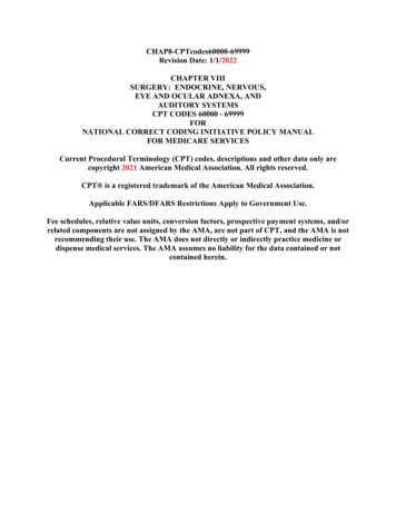
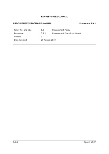
I. OVERVIEWModel Number IdentificationX P 17 036 230 2Refrigerant TypeX R-410AMinor Revision NumberVoltage230 208/230V-1ph-60hzUnit TypeP Heat Pump Outdoor UnitNominal Cooling Capacity024 2 tons030 2.5 tons036 3 tons042 3.5 tons048 4 tons060 5 tonsSeriesTypical Serial Number IdentificationLocation Code19 Saltillo, Mexico58 Marshalltown, IA5 8 09C057165 (or 6) Digit Unique NumberYear Code08 200809 200910 2010Month CodeA JanuaryB FebruaryC MarchSpecificationsUnitModel NumberOutdoor FanSound Rating Number(dB)1Factory RefrigerantCharge2Number of BladesDiameter - inches.XP17-024-230-01, -02, -03, -04, -056210 lbs. 0 oz.526.2XP17-024-230-06. -076310 lbs. 0 oz.526.2XP17-024-230-08639 lbs. 10 oz.526.2UnitModel NumberOutdoor FanSound Rating Number(dB)1Factory RefrigerantCharge2Number of BladesDiameter - inches.XP17-030-230-01, -02, -03, -04, -05, -06,-076710 lbs. 2 oz.526.2XP17-030-230-08, -09679 lbs. 12 oz.526.2UnitModel NumberOutdoor FanSound Rating Number(dB)1Factory RefrigerantCharge2Number of BladesDiameter - inches.XP17-036-230-01, -02, -03, -04, -057010 lbs. 2 oz.526.2XP17-036-230-077110 lbs. 2 oz.526.2XP17-036-230-08719 lbs. 12 oz.526.2UnitModel NumberOutdoor FanSound Rating Number(dB)1Factory RefrigerantCharge2Number of BladesDiameter - inches.XP17-042-230-01, -02, -03, -04, -05, -067111 lbs. 0 oz.526.2XP17-042-230-077211 lbs. 0 oz.526.2XP17-042-230-087210 lbs. 10 oz.526.2XP17Page 2
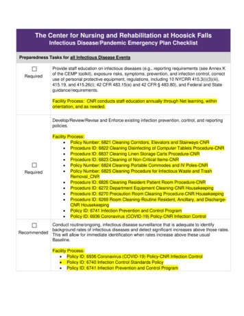
UnitModel NumberOutdoor FanSound Rating Number(dB)1Factory RefrigerantCharge2Number of BladesDiameter - inches.XP17-048-230-01, -02, -03, -04, 05, -067114 lbs. 0 oz.526.2XP17-048-230-077314 lbs. 0 oz.526.2XP17-048-230-087313 lbs. 10 oz.526.2UnitModel NumberOutdoor FanSound Rating Number(dB)1Factory RefrigerantCharge2Number of BladesDiameter - inches.XP17-060-230-01, -02, -03, -04, 05, -06,-077314 lbs. 8 oz.526.2XP17-060-230-087314 lbs. 2 oz.526.21 Testedaccording to AHRI Standard 270-2008 test conditions.2 Refrigerantcharge sufficient for 15 feet length of refrigerant lines.Electrical Data208/230V-60 Hz-1 PhUnitCompressorMaximum Overcurrent 230-01, -02,-03, -0430XP17-024-230-05, -06,-07. -0830Model NumberCondenser FanRated LoadAmps (RLA)LockedRotor Amps(LRA)Motor HPNominal RPMFull LoadAmps /230V-60 Hz-1 PhUnitCompressorMaximum Overcurrent 230-01, -02,-03, -0430XP17-030-230-05, -06XP17-030-230-07XP17-030-230-08, -09Model NumberCondenser FanRated LoadAmps (RLA)LockedRotor Amps(LRA)Motor HPNominal RPMFull LoadAmps 30V-60 Hz-1 PhUnitModel NumberXP17-036-230-01, -02,-03, -04, -05, -07, -08CompressorMaximum Overcurrent denser FanRated LoadAmps (RLA)LockedRotor Amps(LRA)Motor HPNominal RPMFull LoadAmps (FLA)16.779.01/36002.0208/230V-60 Hz-1 PhUnitModel NumberXP17-042-230-01, -02,03, -04, -05, -07, -07,-08CompressorCondenser FanMaximum Overcurrent Protection(amps)1MinimumCircuityAmpacity2Rated LoadAmps (RLA)LockedRotor Amps(LRA)Motor HPNominal RPMFull LoadAmps (FLA)4024.417.9107.01/36002.0208/230V-60 Hz-1 PhUnitModel NumberXP17-048-230-01, -02,-03, -04, -05, -06, -07,-08XP17CompressorMaximum Overcurrent denser FanRated LoadAmps (RLA)LockedRotor Amps(LRA)Motor HPNominal RPMFull LoadAmps (FLA)21.8117.01/36752.0Page 3
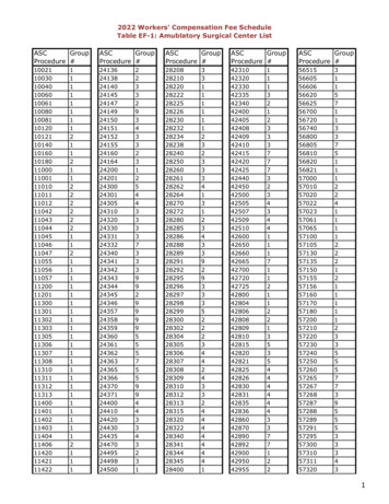
208/230V-60 Hz-1 PhUnitModel 1, -02,-03, -04, -05, -06, -07,-081 HACR2 ReferCompressorMaximum Overcurrent Protection(amps)1Condenser FanRated LoadAmps (RLA)LockedRotor Amps(LRA)Motor HPNominal RPMFull LoadAmps (FLA)26.4134.01/36752.0type circuit breaker or fuse.to National or Canadian Electrical Code manual to determine wire, fuse and disconnect size requirements.Unit Dimensions -- Inches (Millimeters)39-1/2(1003)DISCHARGE AIRELECTRICAL INLETS35-1/2(902)37 (940) [-024 THRU -042] 47(1194) [-048 AND -060]4-7/16(113)VAPOR LINEINLETLIQUID LINEINLET18-1/2(470)8 (203)1 (25)SIDE VIEWACCESS VIEWUNIT 9)3-3/4 (95)30-3/4(781)BASE WITH ELONGATED LEGSXP17Page 44-5/8(117)
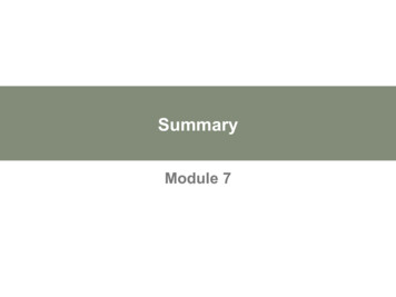
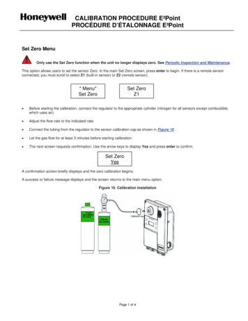
Typical Unit Parts ArrangementSECOND GROUND LUG FOR SOURCESOURCE GROUND LUGWIRE TIEFAN MOTOR CONTROL (A177)CONTACTOR-1POLE (K1-1)HIGH VOLTAGE FIELDCONNECTIONSSLEEVEOUTDOOR AMBIENTTEMPERATURESENSOR (RT13)HEAT PUMPCONTROL (A175)EXTERNAL SURGEPROTECTION USED ONXP17-XXX-230-01 AND -02ONLY). LATER VERSIONSINCORPORATE FEATUREINTO FAN MOTOR.CAPACITOR (C12)CONTROL BOXCOMPRESSORRT21 — MODELS-024, - 030, -036AND -042 (12TUBES NEREVERSINGVALVESOLENOID (L1)MODELS -048AND -06024 TUBES UPVAPOR VALVEAND GAUGEPORTCHECK EXPANSIONVALVEHR1 CRANKCASEHEATERTRUE SUCTIONLINE PORTLIQUID VALVE ANDGAUGE PORTLIQUID LINEBI-FLOW FILTERDRIERCRANKCASE HEATER THERMOSTAT(S40)LOW PRESSURESWITCH (S87)HIGH PRESSURE SWITCH(S4)Figure 1. Typical Parts ArrangementXP17Page 5
IMPORTANTThis unit must be matched with an indoor coil asspecified in Lennox' Product Specification bulletin.Coils previously charged with HCFC-22 must beflushed.WARNINGThis product and/or the indoor unit it is matched with maycontain fiberglass ntenance, or repair will expose you to fiberglass wooldust. Breathing this may cause lung cancer. (Fiberglasswool is known to the State of California to cause cancer.)Fiberglass wool may also cause respiratory, skin, andeye irritation.To reduce exposure to this substance or for furtherinformation, consult material safety data sheets availablefrom address shown below, or contact your supervisor.Lennox Industries Inc.P.O. Box 799900Dallas, TX 75379-9900Operating Gauge SetThese instructions are intended as a general guide and donot supersede local codes in any way. Consult authoritieswho have jurisdiction before installation.TORQUE REQUIREMENTSWhen servicing or repairing HVAC components, ensurethe fasteners are appropriately tightened. Table 1 liststorque values for fasteners.IMPORTANTOnly use Allen wrenches of sufficient hardness (50Rc Rockwell Harness Scale minimum). Fully insert thewrench into the valve stem recess.Service valve stems are factory-torqued (from 9 ft-lbs forsmall valves, to 25 ft-lbs for large valves) to preventrefrigerant loss during shipping and handling. Using anAllen wrench rated at less than 50Rc risks rounding orbreaking off the wrench, or stripping the valve stemrecess.See the Lennox Service and Application Notes #C-08-1for further details and information.IMPORTANTCAUTIONPhysical contact with metal edges and corners whileapplying excessive force or rapid motion can result inpersonal injury. Be aware of, and use caution whenworking nearby these areas during installation or whileservicing this equipment.IMPORTANTThe Clean Air Act of 1990 bans the intentional venting ofrefrigerant (CFCs, HCFCs AND HFCs) as of July 1, 1992.Approved methods of recovery, recycling or reclaimingmust be followed. Fines and/or incarceration may belevied for noncompliance.WARNINGElectric Shock Hazard. Can cause injuryor death. Unit must be grounded inaccordance with national and localcodes.Line voltage is present at all componentswhen unit is not in operation on units withsingle‐pole contactors. Disconnect allremote electric power supplies beforeopening access panel. Unit may havemultiple power supplies.The XP17 is a high efficiency residential split-system heatpump unit, which features a one stage scroll compressorand HFC-410A refrigerant. Units are available in 2, 2.5, 3,3.5, 4 and 5-ton sizes. The series is designed for use withan expansion valve only (approved for use with HFC-410A)in the indoor unit.XP17To prevent stripping of the various caps used, theappropriately sized wrench should be used and fittedsnugly over the cap before tightening.Table 1. Torque RequirementsPartsRecommended TorqueService valve cap8 ft.- lb.11 NMSheet metal screws16 in.- lb.2 NMMachine screws #1028 in.- lb.3 NMCompressor bolts90 in.- lb.10 NMGauge port seal cap8 ft.- lb.11 NMUSING MANIFOLD GAUGE SETWhen checking the system charge, only use a manifoldgauge set that features low loss anti-blow back fittings.Manifold gauge set used with HFC-410A refrigerantsystems must be capable of handling the higher systemoperating pressures. The gauges should be rated for usewith pressures of 0 - 800 psig on the high side and a lowside of 30” vacuum to 250 psig with dampened speed to500 psi. Gauge hoses must be rated for use at up to 800psig of pressure with a 4000 psig burst rating.OPERATING SERVICE VALVESThe liquid and vapor line service valves are used forremoving refrigerant, flushing, leak testing, evacuating,checking charge and charging.Each valve is equipped with a service port which has afactory-installed valve stem. Figure 2 provides informationon how to access and operating both angle and ball servicevalves.Page 6
SERVICE VALVES ANGLE AND BALLOperating Angle Type Service Valve:1. Remove stem cap with an appropriately sized wrench.2. Use a service wrench with a hex-head extension (3/16” for liquid line valve sizes and 5/16” for vapor line valve sizes) to backthe stem out counterclockwise as far as it will go.SERVICE PORT CAPSERVICE PORT CORE(VALVE STEM SHOWNCLOSED) INSERT HEXWRENCH HERE(VALVE STEM SHOWN OPEN)INSERT HEX WRENCH HERETO INDOORUNITSTEM CAPTO OUTDOOR UNITANGLE-TYPE SERVICE VALVE(BACK-SEATED OPENED)ANGLE-TYPE SERVICE VALVE(FRONT-SEATED CLOSED)When service valve is OPEN, the service port isopen to linE set, indoor and outdoor unit.WHEN SERVICE VALVE IS CLOSED, THE SERVICE PORT ISOPEN TO THE LINE SET AND INDOOR UNIT.To Access Service Port:Operating Ball Type Service Valve:1. Remove stem cap with an appropriately sized wrench.2. Use an appropriately sized wrenched to open. To open valve,rotate stem counterclockwise 90 . To close, rotate stemclockwise 90 .TO INDOOR UNITTO OPEN ROTATE STEMCOUNTERCLOCKWISE 90 .TO CLOSE ROTATE STEMCLOCKWISE 90 .BALL (SHOWNCLOSED)VALVESTEM1. Remove service port cap with an appropriately sized wrench.2. Connect gauge set to service port.3. When testing is completed, replace service port cap and tighten asfollows:1/6 TURN With torque wrench: Finger tighten andtorque cap per table 1.11 12 1 Without torque wrench: Finger tighten and210use an appropriately sized wrench to turn93an additional 1/6 turn clockwise.8Reinstall Stem Cap:SERVICE PORTCORESERVICE PORTCAP8STEM CAPNOTE — A label with specific torque requirements may be affixed to the stem cap. If the label is present, use the specified torque.Figure 2. Angle and Ball Service ValvesXP177 6 54Stem cap protects the valve stem from damage and serves as theprimary seal. Replace the stem cap and tighten as follows:1/12 TURN With Torque Wrench: Finger tighten and thentorque cap per table 1.11 12 1 Without Torque Wrench: Finger tighten and210use an appropriately sized wrench to turn anadditional 1/12 turn clockwise.39SERVICE PORTTO OUTDOORUNITA service port cap protects the service port core from contamination andserves as the primary leak seal.Page 77 6 54
II. SYSTEM OPERATION AND SERVICEJumpers, Loops and Terminals (101797-XX)HEAT PUMP CONTROL — ONE STAGEDS11 and DS14E37*30LED ALERT CODESSECOND DELAY30COMPRESSORSHIFT DELAY0SECOND DELAY0E33FIELD TESTDS13 and DS15LED ALERT ETDEFROST TERMINATION TEMPERATUREW1FOR HUMIDITROL — ENHANCEDDEHUMIDIFICATIONACCESSORY(EDA) APPLICATIONS.Figure 3. Jumpers, Loop and Terminals (101792-xx)XP17Page 8
Table 2. Heat Pump Control (A175) Jumper and Terminal DescriptionsBoard IDLabelDescriptionE12PSC Fan240 VAC output connection for outdoor fan.E16PSC Fan240 VAC input connection for outdoor fan.W24VAC output for defrost auxiliary heat output.LThermostat service light connection.Y224VAC thermostat input/output for second stage operation of the unit.Y124VAC thermostat input for first stage operation of the unit.O24VAC thermostat input for reversing valve operationDSHumiditrol InputC24VAC system common (Build -02 or later)i-Input/Output - RSBus data low. Used in communicating mode only with compatible indoor thermostat. (Build -02or later)i Input/Output - RSBus data high. Used in communicating mode only with compatible indoor thermostat. (Build-02 or later)R24VAC system power input (Build -02 or later)E19 and E20O OUT24 VAC output connection for reversing valve.E21 and E22LO-PSConnection for low-pressure switch (2.4 milliamps @ 18VAC)E31 and E32Y1 OUT24 VAC common output, switched for enabling compressor contactor.E24 and E25HS-PSS87 connection for high-pressure switch (E25) and 24VAC (E24) to A177 “R” input.E26FAN 1First Stage and second stage basic and precision dehumidification ECM fan motor 24VDC output connection 1.E27FAN 2Second stage basic and precision dehumidification ECM fan motor 24VDC output connection 2.E28FAN CECM common connection for ECM fan.E18Six position square pin header. P4 provides connections for the temperature sensors.DIS(YELLOW)Not UsedAMB 1 — Outdoor ambient temperature sensor supply.E30AMB (BLACK)AMB 2 — Outdoor ambient temperature return.Range is -40ºF to 140ºFCOIL(BROWN)COIL 1 — Outdoor coil temperature sensor supply.COIL 2 — Outdoor coil temperature sensor returnE33Field TestThis jumper allows service personnel to defeat the timed off control, initiate or terminate a defrost and fieldprogramming of unit capacity feature.E37Comp ShiftDelayThe heat pump control has a field-selectable function to reduce occasional sounds that may occur while the unitis cycling in and out of the defrost mode. When a jumper is installed on the DELAY pins (E37), the compressorwill be cycled off for 30 seconds going in and out of the defrost mode. Units are shipped with jumper installed onDELAY pins. If no jumper is installed, the 30 second compressor shift delay is not active.50*E477090100W1Seven position square pin header. E47 provides selection of the defrost terminate temperature based on the posi tion of the selection jumper. The defrost termination temperature is measured by the defrost coil sensor. Thejumper termination pin is factory set at 50 F (10 C). If the temperature jumper is not installed, the default termina tion temperature is 90 F (32 C). In addition, it provides selection points for enabling the field test mode.Short DS To R Cut for Humiditrol — Enhanced Dehumidification Accessory (EDA) applications.* Factory default settingXP17Page 9
The heat pump control (A175) provides the followingfunctions: Demand defrost algorithmField-selectable defrost termination temperaturesInternal switching of outputsCompressor anti-short-cycle delay.Five strikes lockout safety functionHigh (S4) and low (S87) pressure switchesAmbient (RT13), and coil temperatures (RT21)temperature monitoring and protection.COMPRESSOR ANTI-SHORT CYCLE DELAYThe heat pump control protects the compressor from: Short cycling (five minutes) when there is initial powerup Interruption in power to the unit Pressure or sensor trips Delay after Y1 demand is removed.In non-communicating systems the delay is set for 300seconds (five minutes) and can not be changed. Tooverride timer when active or inactive, place a jumper onthe field test pins between 1 and 2 seconds.In communicating system, the iComfort -enabledthermostat has a separate built-in 5-minute non-adjustableshort cycle protection. Resetting Anti-Short Cycle DelayThe FIELD TEST pins (E33) on the heat pump control canbe jumpered between 1 to 2 seconds to bypass delay.HIGH (S4) AND LOW (S87) PRESSURE SWITCHESThe unit's pressure switches (LO PS - S87 and HI PS - S4)are factory-wired into the heat pump control on the LO-PSand HI-PS terminals, respectively.Low Pressure Switch (LO-PS) — See figure 30 for lowpressure switch sequence of operation.Resetting Five-Strike LockoutOnce the condition has been rectified, power to the heatpump control's R terminal must be cycled OFF, or a jumperplaced on the FIELD TEST pins between 1- to 2-seconds toreset the heat pump control.Defrost SystemThe heat pump control (A175) measures differentialtemperatures to detect when the system is performingpoorly because of ice build-up on the outdoor coil. Thecontroller self-calibrates (see figure 32) when the defrostsystem starts and after each system defrost cycle. Theheat pump control monitors ambient temperature, outdoorcoil temperature, and total run-time to determine when adefrost cycle is required. The coil temperature sensor isdesigned with a spring clip to allow mounting to the outsidecoil tubing. The location of the coil sensor is important forproper defrost operation (see figure 1 for location of coilsensor).NOTE - The heat pump control accurately measures theperformance of the system as frost accumulates on theoutdoor coil. This typically will translate into longer runningtime between defrost cycles as more frost accumulates onthe outdoor coil before the heat pump control initiatesdefrost cycles.DEFROST OPERATING MODESThe heat pump control board has three operational modeswhich are:Defrost calibration and operation (see figure 32) Defrost test (see figure 7)DEFROST TERMINATION TEMPERATURES (E47)The heat pump control selections are: 50, 70, 90, and100 F (10, 21, 32 and 38 C). The jumper termination pin isfactory set at 50 F (10 C). If the temperature jumper is not installed, the defaulttermination temperature is 90 F (32 C). See figure 32 foron how this settings affects defrost calibration and defrostmodes.NOTE - Colder climates could require a high dischargetermination temperature setting to maintain a clear coil.100High Pressure Switch (HI-PS) — See figure 31 for highpressure switch sequence of operation.DEGREETARGETPressure Switch Event SettingsThe following pressures are the auto reset event valuetriggers for low and high pressure thresholds: High Pressure (auto reset) - trip at 590 psig; reset at418.Low Pressure (auto reset) - trip at 25 psig; reset at 40.XP1770DEGREETARGET50DEGREETARGET100907050 IF JUMPER ISNOT INSTALLED(90ºF)90DEGREETARGET100907050Some scroll compressor have internal vacuum protectorthat will unload scrolls when suction pressure goes below20 psig. A hissing sound will be heard when thecompressor is running unloaded. Protector will resetwhen low pressure in system is raised above 40 psig. DONOT REPLACE COMPRESSOR.FACTORY DEFAULT(50ºF)100907050IMPORTANTCOMPRESSOR PROTECTION — FIVE-STRIKELOCKOUT SAFETY FUNCTIONThe five-strike lockout safety function is designed toprotect the unit's compressor from damage. The five-strikefeature is used for high pressure (S4) and low (S87)pressure switch trips and W input fault or miswire.100907050System OperationsFigure 4. Defrost Termination Temperature SettingsPage 10
Table 3. Sensor Temperature / Resistance RangeUNIT SENSORSSensors connect to the heat pump control through afield‐replaceable harness assembly that plugs into thecontrol. Through the sensors, the heat pump controldetects outdoor ambient and coil temperature faultconditions. As the detected temperature changes, theresistance across the sensor changes. table 4 shows howthe resistance varies as the temperature changes for bothtype of sensors. Sensor resistance values can be checkedby ohming across pins shown in table 3.NOTE — When checking the ohms across a sensor, beaware that a sensor showing a resistance value that is notwithin the range shown in table 3, may be performing asdesigned. However, if a shorted or open circuit is detected,then the sensor may be faulty and the sensor harness willneed to be replaced.Ambient Temperature Sensor (RT13)See table 3 for sensor range. If the ambient sensor isdetected as being open, shorted or out of the temperaturerange of the sensor, the heat pump control will not performdemand defrost operation. The heat pump control willrevert to time/temperature defrost operation and willdisplay the appropriate alert code. Heating and coolingoperation will be allowed in this fault condition.Outdoor(Ambient)Figure 5. 10k Resistor LocationXP173 and 4(Black)280,000 to 37505 and 6(Brown)W Input Fault or MiswireIn case of a W input fault or possible miswire, the systemwill function as listed in the sequence of operation in figure33.Shift Delay (E37)The heat pump control has a field-selectable function toreduce occasional sounds that may occur while the unit iscycling in and out of the defrost mode. When a jumper isinstalled on the DELAY pins (E37), the compressor will becycled off for 30 seconds going in and out of the defrostmode. Units are shipped with jumper installed on DELAYpins.*30High Discharge Line Temperature SensorThis model does not use a high discharge line temperaturesensor. The cable assembly attached to the heat pumpcontrol's E30 connection has a 10K resister installedbetween pins 1 and 2 as illustrated in figure 5. No alerts oralarms would be generated if resistor is damage.10K RESISTORPins/WireColorNOTE — Sensor resistance decreases as sensed temperatureincreases (see table 4).See table 3 for sensor range. If the defrost coil sensor isopen, shorted or out of the temperature range of thesensor, the heat pump control will not perform demand ortime/temperature defrost operation and will display theappropriate fault code. Heating and cooling operation willbe allowed in this fault condition.AMBIENT AIRTEMPERATURE SENSOR-40 (-40) to 140(60)Resistance valuesrange (ohms)CoilCoil Temperature Sensor (RT21)COIL TEMPERA TURE SENSORTemperatureRange F ( C)SensorFACTORY DEFAULT OR WHENJUMPER IS MISSINGSECOND DELAY300SECOND DELAY0Figure 6. Shift Delay SettingsTHERMAL PROTECTION SWITCH (S173) COMPRESSOR MOUNTEDSome units are equipped with a compressor mountednormally closed temperature switch that preventscompressor damage due to overheating caused by internalfriction. The switch is located on top of the compressorcasing. This switch senses the compressor casingtemperature and opens at 239-257 F (115 C-125 C) toshut off compressor operation. The auto-reset switchcloses when the compressor casing temperature falls to151-187 F (66 C-86 C), and the compressor isre-energized. This single-pole, single-throw (SPST)bi-metallic switch is wired in series with the 24V Yinput signal to control compressor operation.Page 11
MULTI-FUNCTION TEST PINS (E33)Placing the jumper on the field test pins (E33) using a specific sequence allows the technician to: Clear short cycle lockout Clear five-strike fault lockout Cycle the unit in and out of defrost mode Manually place the unit in defrost mode to clear the coilWhen Y1 is energized and 24V power is being applied to the heat pump control (A175), a test cycle can be initiated by placing a jumper on the heatpump control's TEST pins for 2 to 5 seconds. If the jumper remains on the TEST pins (E33) for longer than five seconds, the heat pump control willignore the jumpered TEST pins and revert to normal operation.The heat pump control will initiate one test event each time a jumper is placed on the TEST pins. For each TEST the jumper must be removedfor at least one second and then reapplied.Y1 ActivePlace a jumper on TEST pins forlonger than one second but lessthan two seconds.Clears any short cycle lockout andfive strike fault lockout function, ifapplicable. No other functions willbe executed and unit will continue inthe mode it was operating.Place a jumper on TEST pins formore than two seconds.Clears any short cycle lockout andfive strike fault lockout function, ifapplicable.ACTIVEIf in DEFROST ModeIf in HEATING ModeThe unit will terminate defrost andenter HEAT MODE uncalibratedwith defrost timer set for a maximum34 minute test.If no ambient or coil sensor fault exist, unit will go into DEFROSTMODE.If ambient or coil faults exist (openor shorted), unit will remain inHEAT MODE.If in COOLING ModeNo further test mode operation willbe executed until the jumper isremoved from the TEST pins andreapplied.INACTIVEO Line StatusNOTE — Heat pump control cannot be force intodefrost mode when the ambient temperature inputfrom the RT13 sensor is above 65ºF (18ºC).NOTE — If ambient or coil fault is detected, the boardwill not execute the TEST mode.If jumper on TEST pins remains inplace for more than five seconds.If jumper on TEST pins is removedbefore a maximum of five seconds.The unit will return to HEAT MODEun calibrated with defrost timer setfor 34 minutes.The unit will remain in DEFROSTMODE until termination on time ortemperature.Figure 7. Test Pin (E33) FunctionsXP17Page 12
Table 4. RT13 Ambient and RT21 Coil Sensors Temperature / Resistance 6-5.2-5.7-6.3-6.9-7.5-8.2-8.8-9.4-10.0-10.6Page 1158754597156069461693
Page 1 2013 Lennox Industries Inc. XP17 Service Literature Corp. 1023-L3 Revised December 2013 INSTALLATION AND SERVICE PROCEDURE XP17 (HFC-410A) SERIES UNITS NOTICE A thermostat is not included and must be ordered separately. A Lennox iComfort -enabled thermostat must be used in communicating applications. In non-communicating applications .