Transcription
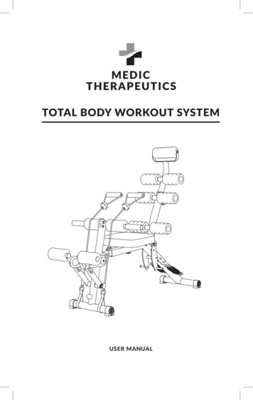
TOTAL BODY WORKOUT SYSTEMUSER MANUAL
Review the user manual carefully prior to first use. To ensure proper product operation,pay special attention to the safety precautions. Retain this user manual for furtherreference.SAFETY PRECAUTIONSTo avoid damage or injury to the user or third parties, read all instructions and safetyrecommendations prior to use of this product. Continue to follow all instructions andguidelines.IMPORTANT NOTICES DURING OPERATION: E lderly or vulnerable people should consult their doctor before using the device, evenif there is no specific precondition for your health. I f you experience pain or any abnormal sensations when using the device, stop useimmediately and consult your doctor. Use the device on a flat surface. If it is not placed on flat surface, the device will not bestable, and could tip over resulting in injury. If the operation of the device begins to look abnormal, stop the exercise immediately. Always store in a cool, moisture-free area. C hildren and individuals with disabilities must not use the device without adultsupervision. To avoid accidents or injuries, do not allow children or pets get on the device. I t should not be used by more than two people at the same time. To avoid accident orinjury, the device should not be used while holding a baby. I f the device fails, consult your dealer or consult the section on Warranty of thisManual. Do not use it for other means than those described in this manual.2
PARTS LIST:Reference ImagesParts ListBase and chairPart # 1Quantity 1Straight RollersPart # 8Quantity 4Bolt 8 * 85Part # 15Quantity 1Screw M10 * 90 allenPart # 22Quantity 1PP ScrewsPart # 29Quantity 2Back SupportPart # 2Quantity 1Grips piecePart # 9Quantity 2Bolt 8 * 45Part # 16Quantity 1Rear LegPart # 3Quantity 1SpringsPart # 10Quantity 2Bolt 8 * 55Part # 17Quantity 1Screw M8 * 55 allenPart # 23Quantity 1PP NutPart # 30Quantity 2PedalsPart # 31Quantity 2Front LegPart # 5Quantity 1ConnectorPart # 4Quantity 1Caps 7Part # 12Quantity 3KnobsPart # 11Quantity 2Back support rollers (A)Part # 18Quantity 3Hex Nut M8Part # 24Quantity 2Washer 8 * 19 * 1.5Part # 19Quantity 19Bushing PP 12 * 27.5Part # 25Quantity 2Washer 8 * 22 * 1.5Part # 32Quantity 23Neck supportPart # 6Quantity 1Backing RollersPart # 7Quantity 3Hex Cap Nut M8Part # 13Quantity 4Screw M8 * 45 allenPart # 14Quantity 1Washer 10 * 20 * 1.5Part # 20Quantity 1Hex Nut M10Part # 21Quantity 1Bushing coverPart # 26Quantity 2Insert bushing 12 * 86Part # 33Quantity 2Screw M6 * 12Part # 27Quantity 2GartersPart # 28Quantity 2Resistance BandsPart # 34Quantity 2
EXPLODED-VIEW DRAWING4
ASSEMBLING INSTRUCTIONSStep 1Attach the back support piece (# 2) tothe base piece and seat (# 1) in the holesindicated with the dotted line of thedrawing using the screw (# 22), washer(# 20) and nut (# 21) that are attachedto the base piece and seat (# 1) usingthe 17mm (11/16”) wrench and the 5mm(13/64”) Allen key.Step 2Attach the back leg piece (# 3) to thebase piece and seat (# 1) at the holesmarked with the dotted line of thedrawing. Take the screw (# 23), washer(# 21) and nut (# 24) and place it on therear leg (# 3). Tighten the screw, washerand nut by using the 13mm (1/2”)wrench and 5mm (13/64”) Allen key.Use the 8 * 55 bolt (# 17) that islocated in the lower hole of the rear legpiece (# 3) to fix the piece in place inactive mode.Step 3Attach the connector piece (# 4) to thebase piece and seat (# 1). Once insideinsert the knob (#11) and slide it to alignthe holes on the connector piece to theknob.These holes are used to be able tochange the length of the devicedepending on the height of the user.Simply pull the knob and adjustconnector piece to desired length.5
Step 4Place the front leg piece (# 5) in theconnector piece (# 4) in the holes indicatedwith the dotted line. Using the screw (#14),washer (#21) and nut (#24) and place themin the base piece and seat (#1). Tighten thescrew, washer and nut by using the 13mm(1/2”) wrench and a 5mm (13/64”) Allen key.This hardware is inside the bag that you willfind inside the packaging.Use the 8 * 55 bolt (#16) that comes insidethe bag that is inside the packaging to placeit in active mode.Step 5Insert the neck support piece (#6)to the back support piece (#2). Onceinside, insert the knob (#12) and slidethe neck support part to align the holesto the knob.These holes are used to change theheight of the neck support dependingon the height of the user.Step 6Place the back roller pieces (#7), one in eachof the bushings found in the neck support(#6) and back support (#2) pieces indicatedwith the dotted line.Next, put the back support rollers (# 20)and at the end, place the caps (#13) on theopposite end of the back roller parts (#7).These caps come inside the bag that you willfind inside the packaging.6
Step 7Insert the straight roller pieces (#9)into the horizontal tubes of thefront leg (# 5) indicated with thedotted line. Next, place the grippieces (#10) on the horizontal tubesof the front leg piece (#5) markedwith the dotted line.Cardio system assemblyAll the parts required to set up the cardio system are insidethe box in the packaging.Step 8Place the bushing (#33) in thehole marked with the dotted lineon the front leg (#5). Next, insertthe bushing piece (#25) into thebushing insert (# 33) followed bythe rubber bands (#28) on the sidewith round holes. Finally, usingthe hub cover piece (#26) and thescrew (#27) fix them using the 5mm(13/64”) Allen key.Make sure to place each of the partsmentioned in the previous stepin the correct order in which it isspecified in the drawing, using thedotted line for reference.7
Step 9Insert the pedals (#31) into the threadedstuds from where you previously removedthe horizontal tubes attached to themiddle of the front leg (# 5). Using thewashers (#32) and nuts (#13) fix them bytightening them with the wrench. Finally,place the straight rollers (#8) in thehorizontal tubes located on the upper partof the pedals (#31).Make sure to place each of the partsmentioned in the previous step in thecorrect order in which it is specified inthe drawing, using the dotted line forreference.Step 10Using the PP nut (#30) and the PPscrew (# 29) attach the band piece (#28) to the pedal piece (#31).Step 11Remove the nuts (#13) found on thehorizontal bolts of the middle part of therear leg (# 3) and place the 2 springs (#10)from its lower end.8
HOW TO USEAdjust the level of back support assistance. To adjust the level of assistance it is necessaryto place or remove the springs, only the upperpart, identified by a hook that attaches to thebolts sides that are at the bottom of the backleg support (# 3) It is necessary to modify this assistancedepending on the weight and physical capacityof the user.Back support position adjustment.Total Body Workout System has 4 options for placing the back support The Total Body Workout System has 4 options for placing the back support. ABS mode: Depending on the amount of springs used, that will be the assistedresistance the user will get without being fixed with the 8 * 85 bolt part (#17). Abdominal bench mode: Place the back support in a position parallel to the ground andfix it by inserting the 8 * 85 bolt (# 17) crossing it through the hole indicated with thedotted line. It is recommended that no springs be attached for easy placement. Fixed mode: Position the back support vertically by inserting the 8 * 85 bolt (# 17)crossing it through the hole marked with the dotted line. It is recommended that nosprings be attached for an easier setup. Folding mode: Remove pin 8 * 85 (# 17) and make sure that no spring is attached.9
Resistance adjustment in cardio system The Total Body Workout System has 3 levels of resistance in its cardio system to beused depending of the physical capabilities of the user. To be able to modify the resistance level, loosen the PP nut, change the level andtighten again. Level 1 higher resistance, Level 3 lower resistance.Resistance band placement The Total Body Workout System has2 resistance bands to work the upperbody, back, shoulder, biceps, tricepsand arms. Attach the resistance bands fromtheir lower end to the front or rear legdepending on the exercise to perform. Secure the level of the resistance bandto the leg correctly to prevent the legfrom coming loose during workouts.10
WARRANTY:Limited Lifetime WarrantyYour Medic Therapeutics Total Body Workout System is backed by a limited lifetimemanufacturer’s warranty. Medic Therapeutics will repair or replace your device at anytime should it fail due to a defect in material or workmanship, subject to the certainlimitations.This limited warranty does not cover any damage that results from unauthorizedor improper use, service, or repair. Further, it does not cover damage caused byaccident, impact, negligence, or normal wear and tear. Should you discover your MedicTherapeutics Total Body Workout System is not functioning properly, please send yourdevice to our repair center for evaluation. If your product cannot be repaired or serviced,we will reserve the right to change it for a similar or newer model.Please note that a flat rate of 60.00 will be charged to cover a service evaluation feeand return shipping of your device. All warranty claims must be accompanied by a copyof your proof of purchase from an authorized retailer. Please send your device, proofof purchase, and a check or money order in the amount of 60.00 made out to MedicTherapeutics to:Address:Medic Therapeutics Service Center3069 Taft StreetHollywood, FL 33009Contact:warranty@medictherapeutics.com11
To be able to modify the resistance level, loosen the PP nut, change the level and tighten again. Level 1 higher resistance, Level 3 lower resistance. Resistance band placement The Total Body Workout System has 2 resistance bands to work the upper body, back, shoulder, biceps, triceps and arms. Attach the resistance bands from