Transcription
2.5 Separation of Systematic ErrorsHale, Layton C. "Principles and techniques for desiging precision machines."PhD Thesis, 1999.2.6 Exact-Constraint DesignBy “dusting off” the principles of kinematics and applying them to machinedesign, we arrive at the method of Exact Constraint. The method of ExactConstraint has been developed to the point where it comprises a body ofknowledge which can be used to routinely create new machine designswhich are both high in performance and low in cost. The results are soexcellent, yet so obvious; so elegant, yet so simple; that at once they seem67
Chapter 2 Precision Engineering Principles both profound and trivial! Perhaps it is this duality which has kept theseprinciples so well hidden. One may ask: “Of what value could anything sotrivial be?” And so these principles have been overlooked. They havebecome disused.[Blanding, 1992]The designers of mechanisms routinely use the principles of kinematics becauseoverconstrained or underconstrained devices simply will not function. What the precisionengineer must remember is that at some scale, everything is a mechanism. The componentthat must remain stable to nanometers will not if it is overconstrained to a structure thatdeforms by micrometers. This is often the most important motivation for exact-constraint orkinematic design in precision machines, that is, to isolate sensitive parts or systems such asa metrology frame from the influence of dimensionally changing supports and/ormanufacturing tolerances.I Similarly, parts will fit together precisely and without backlashif they are exactly constrained, for example, kinematic couplings. This is why [Smith andChetwynd, 1992] state that “a divergence from pure kinematic design results in increasedmanufacturing costs.”IIThe term exact constraint is very explicit and meaningful once the basic concept isunderstood. An unconstrained rigid object has six degrees of freedom usually identified asthree translations and three rotations. A nonrigid object may have one or more degrees offlexibility that act as additional degrees of freedom, relatively speaking. For example, anopen shoe box is torsionally flexible and so would have a total of seven degrees offreedom. The proper application of constraints would eliminate degrees of freedom in aone-to-one fashion. It is the objective of exact-constraint design to achieve some desiredfreedom of motion or perhaps no motion by applying the minimum number of constraintsrequired. Often we conceptualize in terms of an ideal constraint, which is absolutely rigidagainst motion in one or more degrees of freedom and is absolutely free in the remainingdegrees of freedom. A real constraint such as a small-area contact between surfaces, a linkor a bearing, provides one or more degrees of constraint that are relatively much stiffer thanthe degrees of freedom and so approximates ideal behavior.IIIThe reference by Blanding is an excellent introduction to exact-constraint designand rigid structures. Because it is so basic and complete, it forms the basis for thisIThe word kinematic is more often used, but exact constraint is more descriptive and thus is preferred.IIAs a practical matter, purely kinematic designs are generally difficult to achieve; whereas, so called semikinematic designs (for example, Hertzian contact areas instead of frictionless point contacts) generallyprovide acceptable isolation characteristics, greater robustness and lower cost. The quotation might betterread “a divergence from kinematic design theory may result in increased manufacturing costs.” As analternative, the process of replication produces a good fit and is relatively low in cost.IIIIn the case of a sliding bearing or small-area contact, the degree of freedom may be as stiff as theconstraint until sliding occurs. Ideal behavior requires that the frictional force divided by the constraintstiffness be a negligible deflection.68
2.6 Exact-Constraint Designintroductory section. Several other references provide accounts of more specific exactconstraint designs such as [Slocum, 1992], [Smith and Chetwynd, 1992], and [Furse,1981]. In addition, Chapter 6 provides a thorough treatment of exact-constraint design, andexamples of exact-constraint designs appear in Chapter 7. In this section, however, thebasic concepts are introduced through statements that appear in [Blanding, 1992]. Althoughthese statements deal specifically with ideal constraints, they provide the essentialunderstanding of kinematics required for the design of real constraint systems. Followingeach statement is an explanation to reinforce and sometimes extend its meaning. The pointhere is to understand and visualize basic kinematic techniques rather than to apply a bunchof rules that are easy to forget.Statement 1: Points on the object along the constraint line can move onlyat right angles to the constraint line, not along it.A single-degree constraint prevents motion in one direction, the constraint direction,represented by a line in space. The only component of motion allowed by the constraint isperpendicular to the constraint line. If the object is rigid, then all points of the object alongthe constraint line are so constrained. The initial or so called instantaneous motion is alwaysperpendicular to the constraint direction (for ideal constraints). The constraint direction maychange as the object moves in which case the constrained path is curved and theinstantaneous motion is tangent to the curve. For example, any point on a wheel with afixed axle is constrained to a circular path. The constraint direction is radial and theinstantaneous motion is tangent to the circle.Statement 2: Any constraint along a given constraint line is functionallyequivalent to any other constraint along the same constraintline (for small motions).By Statement 1, the instantaneous motion is always perpendicular to the constraintline irrespective of the actual constraint. It follows that any constraint on a given constraintline produces the same instantaneous motion. For small motions about an operating point,the curved path of motion produced by any constraint on the given line is approximatelyequal to the instantaneous motion (or tangent) at the operating point. Thus, any twoconstraints on the same constraint line are approximately equal for small motions.Statement 3: Any pair of constraints whose constraint lines intersect at agiven point, is functionally equivalent to any other pair in thesame plane whose constraint lines intersect at the same point.This is true for small motions and where the two constraintslie on distinctly different constraint lines.IIThe final sentence in Statement 3 was changed from “This is true for small motions and where the anglebetween constraints does not approach 0 (180 )” to allow the possibility of parallel constraints thateffectively intersect at infinity.69
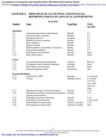
Chapter 2 Precision Engineering Principles The intersection described by this statement is an instantaneous center of rotation,or simply an instant center. The reduction of a constraint pair (or triple) to an instant centeris an important visual and conceptual aid in the field of kinematics. We must distinguish,however, between the stationary point that is on or relative to the constrained body and theinstant center that lies momentarily at this point. The point on the body can have onlyinstantaneous motion that is perpendicular to the plane formed by the two constraints. Inthis plane the point will appear stationary for small motions while the instant center willappear to move with the moving constraint directions. Any pair of constraints that lie in thisplane and intersect the same point will allow the same instantaneous motion of that point onthe body; however, the motion of the instant center may be quite different. Any other pointon the body may have an additional, tangential component of instantaneous motion aboutthe instant center, as shown in Figure 2-16 (a).I.C. atinfinityI.C.path(a)(b)Figure 2-16 In (a), the instant center is momentarily located at the physical center of the circle (heavylines). The instant center moves down (light lines) while the circle rotates approximately about its physicalcenter. In (b), the instant center is off at infinity and the circle initially translates downward.The condition that the two constraint lines be distinctly different requires furtherexplanation as it leads to a key concept. If two constraints were to lie on a single line, thenthey would not define a plane and the statement would not make sense. The physical resultwould be one overconstrained degree of freedom rather than two constrained degrees offreedom. An acceptable case, however, is two parallel constraints that are separate and thusdefine a plane. As Figure 2-16 (b) indicates, we may consider parallel constraint lines tointersect at infinity such as railroad tracks appear at a distance. An object that rotates about adistant center appears to translate such as a ship appears as it rotates about the center of theEarth. With this background, we may conceptualize three translations and three rotations asbeing equivalent to six rotational degrees of freedom where three axes are at infinity.Statement 4: The axes of a body’s rotational degrees of freedom will eachintersect all constraints applied to the body.IIThis is true if each axis provides uncoupled rotation. An example of coupling is the rotation of a leadscrew with its associated translation. The consequence of violating Statement 4 is more complex motion.70
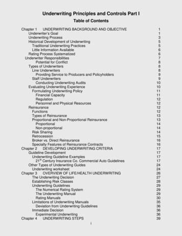
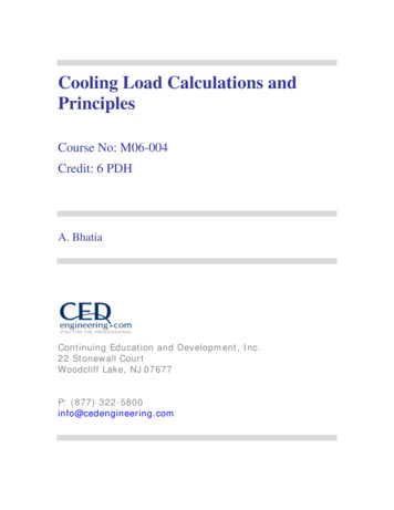
2.6 Exact-Constraint DesignThis is a very powerful and comprehensive statement that uses explicitly therepresentation of translations as rotational axes located at infinity. It is a generalization ofthe instant center and is valuable as a visual aid to understanding a mechanism or insynthesizing the system of constraints for a new mechanism. The proof of this statement isquite trivial. If there exists an axis that intersects all applied constraint lines, then noconstraint exists that can affect a moment about that axis because the lever arm is zero.Hence, the body is free to rotate about that axis, as demonstrated in Figure 2-17.Figure 2-17 All five applied constraints intersect the only remaining degree of freedom, a rotation aboutthe center of the cube.Statement 5: A constraint applied to a body removes that rotational degreeof freedom about which it exerts a moment.In order to constrain a rotational degree of freedom (which includes translations byequivalency), the constraint must react with a moment about the axis of rotation. Aconstraint will satisfy this requirement if the constraint line does not intersect the axis ofrotation and if the constraint line is not parallel to the axis of rotation.I An exception to thefirst condition will result in a zero-length lever arm. An exception to the second conditionwill result in a moment that has no component along the axis of rotation. Figure 2-18shows the addition of a third constraint to prevent rotation of the circle about its center.Each constraint prevents rotation about the instant center formed by the other pair ofconstraints so that three degrees of freedom are exactly constrained. The axes of theremaining three rotational degrees of freedom will each intersect all three constraints perStatement 4. If the three constraints happen to lie in the plane of the figure, then so too willthe axes of rotational freedoms.IJust as parallel constraints intersect at infinity, an axis of rotation and a constraint line that are parallel toeach other also intersect at infinity.71
Chapter 2 Precision Engineering Principles I.C.I.C.I.C.pathI.C.(a)(b)Figure 2-18 The rotational freedom of the circle about its center in (a) is constrained in (b) by theaddition of a constraint that reacts with a moment about the center. Each constraint reacts with a momentabout an instant center formed by the other pair of constraints.The length of the lever arm, that is, a perpendicular drawn from the constraint lineto the constrained rotational axis, is a relative measure of the effectiveness of thatconstraint. If one is seeking a balanced design, then a sensible approach is to seek leverarms having nearly equal length. This leads to a simple rule of thumb for planar problems;arrange constraint lines to form an equilateral triangle, as shown in Figure 2-19. Of coursethere may be valid reasons to choose different angles. Many three dimensional problemshave a planar nature, which greatly helps visualization.I.C.I.C.I.C.I.C. I.C.I.C.(a)(b)Figure 2-19 An equilateral arrangement of constraints often provides a better balance of stiffness. In (a)the center of stiffness lies at the center of the circle, and the vertical and horizontal stiffnesses are equal. Thecenter of the triangular object in (b) is somewhat lower than the center of stiffness. A slightly wider angularspacing between the lower two constraints would lower the center of stiffness while increasing thehorizontal stiffness and decreasing the vertical stiffness.Statement 6: Any set of constraints whose constraint lines intersect acomplete and independent set of rotational axes, isfunctionally equivalent to any other set of constraints whoseconstraint lines intersect the same or equivalent set of72
2.6 Exact-Constraint Designrotational axes. This is true for small motions and when eachset contains the same number of independent constraints.IThis is an extension of Statement 3, the functional equivalence of any constraintpair having the same instant center, based on Statement 4, the generalization of the instantcenter to a rotational axis. The statement is most meaningful and useful when theconstraints total four or more, as at least two pairs of constraints are required to uniquelydefine an axis of rotation. The examples shown in Figure 2-20 are functionally equivalent(for small motions) to each other and to the example in Figure 2-17. Each has fiveconstrai
2.6 Exact-Constraint Design By “dusting off” the principles of kinematics and applying them to machine design, we arrive at the method of Exact Constraint. The