Transcription
Payment Express Colour Mini Vend (CMV)Hardware GuideVersion 0.1
DOCUMENT REVISION INFORMATIONVersion0.1Revision InformationInitial version.RELATED DOCUMENTSVersion1.6.76A00Document TitlePayment Express SCR Serial Communications – SCR Serial Message SpecificationMI0022 Mounting Diagrams CMV300COPYRIGHT Copyright 2017, Payment Express Limited33 Wilkinson Road, EllersliePO Box 8400Auckland, 1150New Zealandwww.paymentexpress.comAll rights are reserved. No part of this work may be reproduced or copied in any form or by any means, electronic ormechanical, including photocopying, without the express written permission of Payment Express Ltd.PROPRIETARY NOTICEThe information described in this document is proprietary and confidential to Payment Express Limited. Any unauthoriseduse of this material is expressly prohibited except as authorised by Payment Express Limited in writing.
CONTENTSDocument Revision Information . 2Related Documents . 2Copyright . 2Proprietary Notice . 21234567Overview . 11.1Terms and Acronyms . 11.2Hardware Models . 11.3Connectivity Diagram . 1CMV300 (AB0146) . 22.1CMV300 Dimensions & Cut-Out. 32.2CMV300 Installation . 3Cables . 73.18-PIN Connector Pin-out . 73.28-Pin to RJ45 Connector Pin-out. 7Secure Acceptance . 84.1Serial Numbers . 84.2Sign of Tampering . 8Activation . 95.1Authorised Customer Agents . 95.2Activation Process. 9Maintenance. 106.1Tradeouts & Deactivation Process . 106.2Maintenance Cards . 106.3Cleaning Instructions. 10Appendix . 117.1Contact Payment Express . 11
11 OVERVIEWThe Payment Express Colour Mini Vend (CMV) solution offers a complete solution for taking ICC Chip/Contactlesspayments in an unattended environment.Payment Express develops and owns the hardware design, intellectual property and processor platform to ensure end toend accountability from card read to bankcard provider.1.1TERMS AND ACRONYMSTermExplanationPINPersonal Identification Number. In the context of card transactions this is typically a secret four digitvalue, entered to approve a transactionPCIPayment Card Industry Standards Security Council (established 2006). Set data security standards forhardware and software in the payments industryPTSPIN Transaction Security. As set of standards applied to a security standards applying to securedevices such as the CMV300CMVColour Mini Vend (version 300)CRCCyclic Redundancy CheckMCUMain Control UnitRSARSA algorithmAESAdvanced Encryption StandardICCIntegrated Circuit Card (chip card/smart card)HostThe Payment Express Host. Provides e-commerce services on the internet1.2HARDWARE MODELSThe CMV solution consists of a core module, anti-removal device and mounting nuts.Standard UnattendedModelCMV300PX Product CodeAB0146Brief Description Base moduleAnti-removal device (AB0170)M4 flange nuts (MF0099)Please note that these are our standard models. When ordering or querying about a particular product please mentionthe PX Product Code. Please contact Payment Express if you require a bespoke solution (see Appendix 7 for contactdetails).1.3CONNECTIVITY DIAGRAMCMV300RS232 SerialHOSTEQUIPMENT
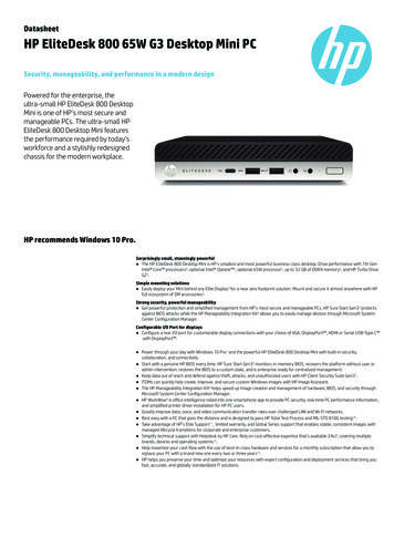
22 CMV300 (AB0146)CMV300 Front ViewHardware Overview Front Mount Design Hardware accelerated encryption (Triple DES,RSA and AES) and a CRC engine Combined magnetic stripe card and ICC cardreader interfaceCMV300 Rear View RS-232 serial ports x1Secure crypto MCU designed for POSapplicationsDedicated tamper grid and removal switchmonitorPhysical Link InterfacePlease refer to the above photo (CMV300 Rear) for reference. Connection with the customer equipment is via the 8-pin port labelled “HOST”. Connection for the anti-removal device labelled “SEC”Power RequirementsThe device accepts DC regulated from 9V to 43.5V. SELV (Safety Extra Low Voltage)When idle (no card inserted), power of 1400mW is drawn and when active 2800mW is drawn (3200mW max).Operating & Storage Temperature RatingsStorage: -20 to 80 degrees (Celsius)Operating: -20 to 75 degrees (Celsius)Standards & Compliance EMV Contact Level 1 & 2 EMV Contactless Level 1 IN PROGRESS PCI SRED (Secure Reading and Exchange ofData) v5 IN PROGRESSAdditional CommentsThis device complies with Part 15 of the FCC Rules. Operation is subject to the following two conditions:1. This device may not cause harmful interference, and2. This device must accept any interference received, including interference that may cause undesiredoperation.
3Changes or modifications not expressly approved by the party responsible for compliance could void the user’sauthority to operate the equipment.2.1CMV300 DIMENSIONS & CUT-OUTRecommended cut out dimensions for customer equipment.Please note that mounting plates are not supplied by Payment Express Hardware and is the responsibility of thecustomer to arrange their selected mounting method. All non-dimensioned lengths are subject to individual customermachine fronts.2.2CMV300 INSTALLATIONDRAWING REQUIRED#PX Product CodeDescriptionDefault QTY1AB0146CMV30012AB0170CMV300 M4 SEC with FPC Connector1 (included with AB0146)3MW0142CMV300 communications cable14MF0099Nut M4 Flange OD 12mm4 (included with AB0146)Machine Mounting Plate (Customer Equipment)Refer to Section 2.115
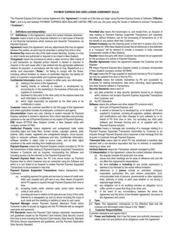
4Installation Steps:1. Prepare the mounting surface in accordance with the MI0020 mounting instructions. Make sure the edge of thehole is smooth.2. Connect the SEC (2) to the rear of the CMV300 as shown3.Insert the communications cable (3) into the rear of the CMV300 as shown.
54.Remove the four nuts (4) from the CMV300.5.6.Feed the SEC (2) and communications cable (3) through the hole in the mounting plate.Insert the CMV300 into the Machine Mounting Plate (5).
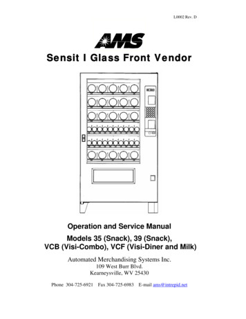
67.Fit 3 of the M4 nuts (4) to the CMV300 mounting studs and tighten to 1.5 Nm.Nut over SEC(3) uses lowertorque.8.Mount the SEC (3) on the remaining mounting stud, fit the remaining M4 nut (4), and tighten to 0.8 Nm. EnsureM4 SEC (3) is mounted with silicone facing the M4 Flange Nut (4).Silicone insertfaces away frommounting plate9. Connect the communications cable to the Host Application (customer application specific)10. The device now needs to be activated before it can be used. Activation is done via a dual control process. Referto Section 5 (Activation) of this document for more information.
73 CABLES3.18-PIN CONNECTOR PIN-OUTThe interconnection between the CMV and the host application is made by a cable plugged into the 8-pin port. The pinson this cable are allocated as follows:Pin IDSignalTypeDescription1TXOutput from CMV300Transmit out. RS232 level, 115Kbps max2RTSOutput from CMV300Request-To-Send. RS232 level3RXInput to CMV300Receive in. RS232 level, 115Kbps max4PWRPower9Vdc to 43.5Vdc.5PWRPower6CTSInput to CMV300Clear-To-Send. RS232 level.7GND-System Ground8GND-3.28-PIN TO RJ45 CONNECTOR PIN-OUTThe standard cable for use with the CMV300 is MW0142. This crosses over the input and output signal lines to plug intohost equipment. The connections for the 8-pin end are as above, and the connections for the RJ45 are as follows:Pin IDSignalTypeDescription1RXInput to CMV300Receive in. RS232 level, 115Kbps max2CTSInput to CMV300Clear-To-Send. RS232 level.3TXOutput from CMV300Transmit out. RS232 level, 115Kbps max4PWRPower9Vdc to 43.5Vdc.5PWRPower6RTSOutput from CMV300Request-To-Send. RS232 level7GND-System Ground8GND-
84 SECURE ACCEPTANCEThe CMV is a security device; therefore, the customer must check the following before installation.4.1SERIAL NUMBERSEach unit (CMV) has their own unique serial number. Upon receiving the unit, the customer must check to ensure thatthe serial number on the box matches the serial number on the unit.Any discrepancies need to be reported to Payment Express (see Appendix 7.1 for contact numbers).Firmware versionnumberProduct nameSerial number(samples shown)Assembly andversion number4.2SIGN OF TAMPERINGThe device should be checked upon receipt and then bi-monthly for the following signs of tampering: The exterior of the device should have no (new) holes, signs of adhesives or stickers other than the device label(as shown in Error! Reference source not found.a) Only one silver-coloured magnetic read head should be visible on the magnetic swipe slot No wires or foreign objects should be visible in the chip card reader slot as shown in Figure 1.(a)(b)Figure 1: Foreign object and wires inserted into the device’s chip card reader slot. a) Normal slot – no wires visible.b) Tampered slot - wires have been routed into right hand side of slot.If any of the above signs of tampering is detected, please cease using the device immediately and arrange to return thedevice to Payment Express Ltd. for examination per Section Error! Reference source not found.4.3LOSS OR THEFTIn the event that a CMV300 device is lost or stolen, please notify Payment Express immediately (see Appendix forcontact information).
95 ACTIVATIONThe CMV300 solution requires activation before the devices can begin processing. Activation is required for initialinstallations and re-installations. Activation is done via a dual control process.5.1AUTHORISED CUSTOMER AGENTSPrior to the installation process beginning two or more customer agents are authorised by Payment Express for theactivation of devices. The customer agents are trusted individuals nominated by the customer.Once the customer agents are established, Payment Express will issue a unique login (username/password) to eachcustomer agent. These logins are used to access the Payment Express website required for the dual control Activationprocess.5.2ACTIVATION PROCESSTwo authorised customer agents must be available for the Activation process to begin.1.Log on to Payment ExpressTwo of the authorised customer agents start separate sessions to log on to the Payment Express website usingtheir individual logins.2.Identify Terminal(s)Once logged in, the terminals available for installation are displayed.3.Authorise Terminal(s)Both of the customer agents will authorise the terminal(s) for installation via the Payment Express website. Thisauthorisation will require a password.When both agents approve a terminal for installation the host terminal information will enter into the “Ready forInstallation” state pending communications from the terminal. This “Ready for Installation” state will revert to a“Removed” state if physical installation and communication with the terminal do not occur within 24 hours. Theagents will need to start the Activation process again if this occurs.For audit purposes, a record will be created in the Payment Express host database for all state changes(including the login used and a timestamp).Utilizing the 24 hour window, authorised customer agents can choose to begin the Activation process at thetime of physical installation or initiate the Activation process prior to the physical installation if they know thephysical installation will be done within the next 24 hours.4.Physical InstallationWithin the 24 hour window, the installation technician will physically install the CMV300 into their mountings.The devices must be connected to communications and the secure channel established to the CMV300.5.Terminal LogonThe installation technician will trigger a transaction via the vendor’s point of sale which will fail with a removaldetection error code (W0) and an on-screen message “MAINTENANCE IN PROGRESS”. The terminal firmwarewill automatically force a logon, upon which the terminal state is then updated.6.Ready State (Activation Process Complete)The terminal and is now authorised for processing transactions. The installation technician should run anothertest transaction (using a valid payment card) to confirm correct operation. This transaction should successfullyprocess.
106 MAINTENANCE6.1TRADEOUTS & DEACTIVATION PROCESSIn the event that the CMV300 device needs to be swapped out or deactivated, please follow instructions below.1.2.3.6.2Call Payment Express Support to log a ticket (see appendix 10.1 for contact numbers). Please provide thefollowing information. Serial Number(s) of CMV300 device(s). Brief description of fault / reason for deactivation. Contact Name. Contact Phone Number. Shipping Address (for replacement if needed).Physically remove the device(s). At next communication with the host the device will be marked as removed.Ship the device(s) back to Payment Express.MAINTENANCE CARDSThe card reader slot in the CMV unit should be checked on a regular basis. This is to ensure that nothing is lodged insidethe card reader slot that may prevent successful card reads or pose a security threat.The card reader slot can be checked by using a standard maintenance card or standard credit card to ensure smoothinsert & remove operation.6.3CLEANING INSTRUCTIONSThe external face of the CMV300 device should be carefully cleaned on a regular basis. This is to ensure that thekeyboard and display are free of dirt and solvents which could damage the device or prevent users from using the deviceas intended.Payment Express recommend cleaning the device with a damp cloth. Do not use any solvents as this may damage thedevice surface.
117 APPENDIX7.1CONTACT PAYMENT EXPRESSPhoneInternational 64 9 309 4693Australia1 800 006 254 or 61 2 8268 7700Hong Kong 852 3 678 6766New Zealand0800 PAYMENT (729 6368) or 09 309 4693Singapore 65 3 158 1353South Africa 27 10 500 8784United Kingdom 44 (0) 20 3176 5551USA 1 310 670 ort@paymentexpress.comDev Supportdevsupport@paymentexpress.com
The Payment Express Colour Mini Vend (CMV) solution offers a complete solution for taking ICC Chip/Contactless payments in an unattended environment. Payment Express develops and owns the hardware design, intellectual property and processor platform to ensure end to end accountability from card read to bankcard provider. 1.1 TERMS AND ACRONYMS