Transcription
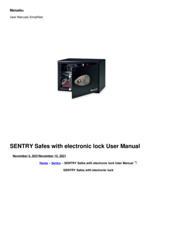
Electronic Safe Lock Axessor USBOperating ManualEN
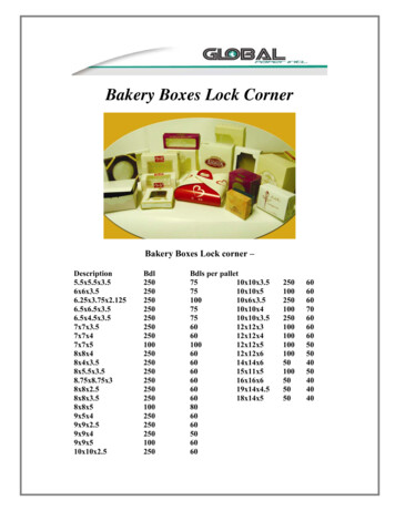
Axessor USBSystem overview - Electronic safe lock Axessor USB21419peTyo.tNPar No.ialSer nrsiots.Vexxorss XXXXXAxe XXX XX/X08XXXX20XX X.XXXXXX xxx.xx815Cer341 2 3 4 5 6 7 810913S111Vd1218175167620Operating ManualSubject to change without prior noticeA21-L-02-02 Axessor USB Manual EN.pdfPage 3
Axessor USBInput Unit1 Housing2 Connection cable to lock unit3 Interface (USB) for PC connection4 ENTER key (enter, confirm)5 INFO/ESC key (activate info display or escape/go back to upper level)6 Battery compartment7 MODE key (activate Programming Mode)8 LEFT and RIGHT key (directional keys to navigate)9 0 . 9 (numeric keys 0.9)10 DEL key (delete, close lock)11 LCD (liquid crystal display)12 BuzzerLock13 Lock housing14 Terminal blocks (Inputs/Outputs)15 Pin for cable tie holder16 Connecting socket X1 (cable from input unit) and X2 (external power supply)17 Warranty seal18 Type label19 VdS-label (protects spring bolt setting screw)20 External power supply (option)A21-L-02-02 Axessor USB Manual EN.pdfPage 4Operating ManualSubject to change without prior notice
Axessor USBTABLE OF CONTENT1Introduction91.1To the very beginning91.2Notes regarding the Operating rget groupLimitationSupplementary documentationSymbols used in this operating manualText markingSafety and Environment99991010112.1General112.2Qualification of personnel112.3Prohibited modifications to the unit112.4Environment11Product overview123.1Product description123.2Field of application133.3Intended use13Installation144.1Important information prior to the installation144.2Upacking and checking the delivery144.3Installing the Input Unit154.4Installing the lock204.5Perform wiring check after lock installation224.6External connections at the lock23Operating ManualSubject to change without prior noticeA21-L-02-02 Axessor USB Manual EN.pdfPage 5
Axessor USB5Operating255.1Operating and display elements of the Input Unit255.2Operating modes265.35.2.1Normal operating mode5.2.2Programming mode5.2.3Information menuBuzzer signals262626275.4Status messages275.55.4.1Locked5.4.2Open5.4.3Immediate time lock5.4.4Time lock (Weekly)5.4.5Time lock (Holiday)5.4.6Time Delay5.4.7Confirmation after elapse of Time Delay5.4.8Enter second code (Dual Mode activated)5.4.9Penalty after wrong trials5.4.10Remote Disabling5.4.11Identification with denied code5.4.12The battery compartment has been opened5.4.13Connected with Programming Software5.4.14External power supply availableAccess Codes2727272828282829292929303030315.65.5.1Code hierarchy and code formats5.5.2Code types5.5.2.1Master Code5.5.2.2Manager Codes5.5.2.3User Codes5.5.2.4Courier Code5.5.3Shelve Function5.5.4Duress CodeCode entry3131323333333434355.7Opening procedure365.8Closing procedure38A21-L-02-02 Axessor USB Manual EN.pdfPage 6Operating ManualSubject to change without prior notice
Axessor USB6Programming Mode396.1Operating the programming mode396.26.1.1Activating the programming mode6.1.2Navigating in the Programming Mode6.1.3Modify and save settings in the Programming Mode6.1.4Exiting the Programming ModeMenu overview39404041426.3Access .56.4.5.16.4.5.26.4.5.36.4.5.46.4.5.5Menu TIMESetting the time - submenu TIMESetting the time - submenu DATESetting the time format - submenu AM/PMMenu PROGConfiguring Weekly Locking Periods - Submenu WEEKLYAdding a Weekly Locking PeriodModifying an existing Weekly Locking PeriodDeleting an existing Weekly Locking PeriodActivating an Immediate Time Lock - Submenu IMM-TLConfiguring Holiday Locking Periods - Submenu HOLIDAYAdding a Holiday Locking PeriodModifying an existing Holiday Locking PeriodDeleting an existing Holiday Locking PeriodMenu DELAYSetting/Deactivating Time Delays - Submenus DELAY 1.2Configuring the Confirmation Window - Submenu CNF WINMenu CODEChanging the Master Code - Submenu MASTERSetting Manager Codes - Submenu MANAGERSetting User Codes - Submenu USERSetting the Courier Code - Submenu COURIERReset the whole Axessor USB safe lock system tofactory defaults - Submenu SHELVEModifying a codeDeleting a codeMenu MISCActivating/Deactivating Code Denial - Submenu CDE DENActivating/Deactivating Remote Disabling Submenu RMT-DISActivating/Deactivating Duress Code function Submenu DURESSActivating/Deactivating Dual Mode - Submenu DUALSetting the display language - Submenu LANGOperating ManualSubject to change without prior notice616263646465666768A21-L-02-02 Axessor USB Manual EN.pdfPage 7
Axessor USB789Servicing697.1Cleaning697.2Replacing the batteries697.3Customer Service707.4Spare parts and accessories71Error messages72Technical 9.4Approvals and Certificates799.5Factory settings80A21-L-02-02 Axessor USB Manual EN.pdfPage 8Operating ManualSubject to change without prior notice
Axessor USB1Introduction1.1To the very beginningWe thank you for having opted for the electronic safe lock Axessor USB.The electronic safe lock Axessor USB incorporates the latest technical advancesand meets all recognized safety standards. Nevertheless, improper use of theelectronic safe lock Axessor USB may result in impairment of material assets.To ensure a safe, proper, and economical operation of the electronic safe lockAxessor USB, please observe and comply with all information and safety instructions contained in the present Operating Manual as well as the instructions givenin the manuals for the components used in conjunction with the safe lock.If you have questions, which are not or insufficiently answered in this OperatingManual, please contact your supplier. They will be glad to assist you.1.2Notes regarding the Operating Manual1.2.1ValidityThis Operating Manual describes the electronic safe lock Axessor USB.1.2.2Target groupThis Operating Manual addresses itself to well trained personnel which is incharge with the installation, the commissioning, the operation, the servicing andthe trouble shooting of the electronic safe lock Axessor USB.1.2.3LimitationThis Operating Manual is restricted to the installation, commissioning, operation,servicing and trouble shooting of the electronic safe lock Axessor USB.The optional AS 284 Programming Software is only described insofar as this isnecessary for proper operation of the safe lock. Further information on the AS284 Programming Software can be obtained in the help function of the software.1.2.4Supplementary documentationThis operating manual is supplemented with the Axessor USB Quick ReferenceGuide.Operating ManualSubject to change without prior noticeA21-L-02-02 Axessor USB Manual EN.pdfPage 9
Axessor USB1.2.5Symbols used in this operating manualThe following symbols are used in this operating manual to direct your attentionon particular situation, e.g. to indicate a hazardous situation, requirements whichmust be met, etc.:Warning!Indicates a hazard which can cause damage to the unit or have a serious effecton the function or use of the unit if unobserved.Important!Indicates important information which must be observed during the describedprocedure.Note!Indicates notes, information or pointers, which facilitate work or provide additionalbackground information or point out specific details.Requirement!Indicates requirements that must be met for the execution, activation, modification or deletion of the described function. These requirements must be met beforeproceeding.AS 284 Programming SoftwareRefers to the AS 284 Programming Software (optionally available), which allowsadditional settings and functions.1.2.6Text marking The character „ “ stands for „see“, „refer to“ or „also consult“Sample: for a description of Access Code Hierarchy Code hierarchy andcode formats on page 31). Text appearing on the display is marked in capitals and set into quotationmarks (sample: „LOCKED“). Keys to be used are marked in bold capitals and set into angle brackets: DEL Delete key NUMERIC Numeric keys 0 9 INFO/ESC Information/Escape key ENTER Enter key MODE Mode key LEFT Left arrow key RIGHT Right arrow keyA21-L-02-02 Axessor USB Manual EN.pdfPage 10Operating ManualSubject to change without prior notice
Axessor USB2Safety and Environment2.1GeneralEvery person working with the Axessor USB must have read and understood theoperating manual before carrying out any work.Knowing and understanding the contents of the operating manual is a basicrequirement for protecting the personnel against any kind of danger, to preventfaulty operation, and to operate the unit safely and correctly.2.2Qualification of personnelAll actions described in the present operating manual (installation, commissioning, operation, etc.) must be carried out only by well trained and sufficientlyqualified personnel.For safety and warranty reasons any action beyond the scope of this manualmust be carried out only by qualified personnel authorised by the manufacturer.It is assumed that all persons working with the Axessor USB are familiar andcomply with the appropriate regulations on work safety and the prevention ofaccidents.2.3Prohibited modifications to the unitModifications on the electronic safe lock Axessor USB are explicitly not recommended, it may void warranty and impair the security and safety of the unit.For the replacement of defective components use exclusively original accessoriesand spare parts available from your supplier.2.4EnvironmentPacking and consumable material (e.g. batteries) must be disposed of and/orrecycled according to the local regulations.At the end of the service life the unit and its components must be returned to themanufacturer or to a collecting point for disposal or recycling according to thelocal regulations.In case of doubt please contact your supplier.Operating ManualSubject to change without prior noticeA21-L-02-02 Axessor USB Manual EN.pdfPage 11
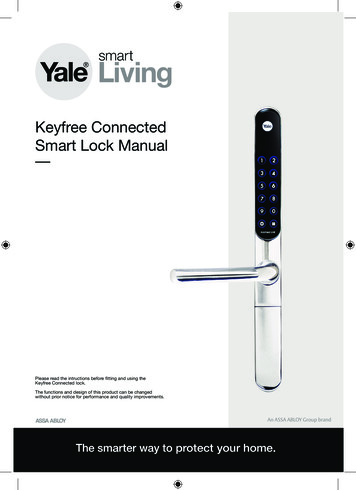
Axessor USB3Product overview3.1Product descriptionThe electronic safe lock Axessor USB is an intelligent motor-bolt lock with integrated terminals used for instance to connect to an alarm centre. It features awide range of functionalities, such as a code hierarchy with User Group management, Courier Code, Dual Mode, Duress Code, Time Delay, Time Lock functions,Remote Disabling and Code Denial. The operation and the programming is donevia the Input Unit.The electronic safe lock Axessor USB may also be configured with the AS 284Programming Software (optionally available). This gives access to an evenenhanced functionality and allows customer-tailored solutions to almost everyextent.Unit configuration standard versionVdSCepeTy.rt NoPa No.lriaSeonrsi.rtsVe90srier sesoXXXXesAx XXXX X/XXX07XX20XX X.XXXXXxXX8.x041 2 3 4 5 6 7 8In its standard version the electronic safe lock Axessor USB is battery poweredand consist of: the input unit, the lock and the connection cable. The lockincludes 2 inputs and 2 outputs (assignment External connections at the lockon page 23). Optionally, an external power supply (6VDC/500mA) can be connected to one of the lock sockets „X1“ or „X2“.Only use the original Axessor USB power supply. Even if the external powersupply is connected, the batteries must remain in the battery compartment at alltimes. They are mainly but not exclusively used in case of a power failure. Onlyuse non rechargeable AA Alkaline or AA Lithium batteries.A21-L-02-02 Axessor USB Manual EN.pdfPage 12Operating ManualSubject to change without prior notice
Axessor USB3.2Field of applicationThe electronic safe lock Axessor USB provides a wide range of functions for applications in the high security sector. They permit programming of various codesand code combinations, time related functions as well as storage and recall of adetailed event log (Audit Trail).The programming can be done via the input unit or by connecting a computerrunning the AS 284 Programming Software to the input unit via USB cable.This electronic safe lock is especially suitable for applications where high security,multiple users, traceability and flexibility are required.3.3Intended useThe electronic safe lock Axessor USB serves to block and release the mechanicalblocking point of a safe, vault, data cabinet, ATM etc. which is usually activatedmanually by a boltwork. The electronic safe lock Axessor USB can be employedinstead of a mechanical combination or key lock. Applicable regulations andstandards have to be observed.Enabling (lock opening) is only performed upon entry of one or several codes onthe Input Unit. The opening procedure can also be made dependent on time functions and/or external signals.The electronic safe lock Axessor USB may only be employed and operated in accordance with its intended use – blocking and releasing the mechanical blockingpoints of above mentioned equipment. Any other type of application is explicitlynot recommended.The electronic safe lock Axessor USB is designed for indoor applications(environmentally protected areas) – they are not suitable for direct exposure toenvironmental impact.Operation of the equipment in the intended manner requires that all the information in this operating manual is observed.Operating ManualSubject to change without prior noticeA21-L-02-02 Axessor USB Manual EN.pdfPage 13
Axessor USB4Installation4.1Important information prior to the installationWarning!Please observe the following: Compliance to described sequence is a necessity. Improper assembly or different sequence may cause damage to the unit! To avoid any damage make sure to keep cables away from moving parts! Donot lead cables over sharp edges! Do not close the safe door until all installation steps have been completedsuccessfully!Important!Please observe the following: Removal of or damage to the warranty seal ( System overview - Electronicsafe lock Axessor USB on page 3, item 17) voids warranty! The mounting screws must be secured against loosening, e.g. by usingscrew cement, such as LOCTITE 243 (medium, blue). Removal of or damage to the VdS label ( System overview - Electronic safelock Axessor USB on page 3, item 19 ) voids VdS approval! The lock must not be mounted directly behind leadthroughs! Clog or secureleadthroughs correspondingly. A suitable cover plate to protect the lock isavailable from your supplier (52x DPUL drilling protection plate).4.2Upacking and checking the deliveryUnpack the delivery and check the content of completeness.The Axessor USB delivery includes: Input Unit Lock Connection cable Plastic bag containing installation material 3 batteries AA-size Instruction leaflet with further information and reference to homepageThe optional computer software packages include: AS284-USBW: CD, USB cable, 1 x Operator dongleA21-L-02-02 Axessor USB Manual EN.pdfPage 14Operating ManualSubject to change without prior notice
Axessor USB4.3Installing the Input UnitMounting the base plate1. Mark either the fixation bores 3 and 5 or 2 and 4 plus bore 1 (recommended). Also mark one of the two bores 6 (cable leadthrough) Do so according tothe illustration below or by using the template ( Template Input Unit on page83).141.326404 x M45510610519334902. Drill the 3 fixation bores Ø3.2 x 14 mm and the cable leadthrough boreØ10 mm. Remove burrs. Tap M4 threads into the 3 fixation bores.Operating ManualSubject to change without prior noticeA21-L-02-02 Axessor USB Manual EN.pdfPage 15
Axessor USB3. Remove the 3 screws on the bottom of the cover (1 at the battery compartment, 2 at the housing). Lift-off the cover from the base plate, then carefullyremove the battery compartment.4. Fix the base plate with the enclosed special M4x12 flat-head screws to thedoor.The Input unit must be fixed to the door with at least two oppositelypositioned screws. The third screw (Pos. 1) is recommended.A21-L-02-02 Axessor USB Manual EN.pdfPage 16Operating ManualSubject to change without prior notice
Axessor USBConnecting the cables5. Carefully lead the enclosed connection cable through the Ø10mm bore in thedoor and carefully draw it towards the lock chamber.6. Mount battery compartment in place. Then, carefully lead the battery cablethrough strain relief guides of the battery compartment and the base plate.Make sure not to squeeze the cable!Finally check for free movability of the battery compartment.Make sure the spiral cable lays flat when moving the battery compartment (i.e. the cable does not move in other directions when extendedand compressed).Operating ManualSubject to change without prior noticeA21-L-02-02 Axessor USB Manual EN.pdfPage 17
Axessor USB7. Position the cover on top of the base plate in an angle 90 .8. Plug the battery cable into the 2 pole connection terminal and the connectioncable into the 6 pole connection terminal.Check correct position of the plugs before connecting them. Do notuse excessive force to plug-in, but make sure that proper connection isgiven.BatteryLockA21-L-02-02 Axessor USB Manual EN.pdfPage 18Operating ManualSubject to change without prior notice
Axessor USBMounting the cover9. Engage the cover at notch on top of base plate.10. Slowly flip down the cover onto the base plate while carefully pulling the connection cable towards the lock chamber; leave some spare loop.Make sure that cables are not squeezed. Check battery compartment forfree movability: carefully push the battery compartment into place, then slideit out again.11. Fix the cover on the base plate using two M3x6 countersink screws.12. Check battery compartment for proper movability: carefully push the batterycompartment into place, then slide it out againDo not insert the batteries and do not fix the battery compartmentscrew yet.Operating ManualSubject to change without prior noticeA21-L-02-02 Axessor USB Manual EN.pdfPage 19
Axessor USB4.4Installing the lockMounting the lock3 x Ø51. Mark the 3 fixation bores (A) according to the illustration below or by usingthe template ( Template Lock on page XXXSerial No.XXXXXXXXXXPart No.AXESSORType2 x M4VdS41.31 2 3 4 5 6 7 87.81525.22.5A66.77.92. Drill the bores Ø5mm. Remove the burrs and tap M6 threads into the bores.3. Mount the lock with the 3 enclosed M6x10 screws (equivalent Inch screwsmay be used instead).Make sure that the screw heads rest on the base of the shoulderedbore! Make sure to keep the space underneath the lock free for a relocker system or the connection cable!4. If the lock is to be operated in spring bolt function, remove the retainer screw(B) underneath the VdS label.Be aware, that this operating mode voids VdS approval!BA21-L-02-02 Axessor USB Manual EN.pdfPage 20Operating ManualSubject to change without prior notice
Axessor USB5. If needed, use the two M4 threads at the front end of the lock bolt to attach anextension.Observe the maximum moving force of 5N in both directions.11.5max. 1000NVdSCerts.2008max. 5Nmax. 1000NXXXXX.XXXXXX/XXXSerial No.XXXXXXXXXXPart No.AXXESSOR seriesType2 x M4max. 1000Nxxxxx.xxVersion1 2 3 4 5 6 7 87.81525.213Connecting the cable6. Verify correct position of the connector, then carefully plug connection cableinto one of the lock sockets „X1“ or „X2“.VdSCerpeTyo.tNPar No.ialSer nrsiots.VexxRSO XXESXXXAX XXX XX/X08XXXX20XX X.XXXXXX xxx.xx1 2 3 4 5 6 7 8X1,X27. Secure the cable with the cable tie and carefully fix any excess cable.Operating ManualSubject to change without prior noticeA21-L-02-02 Axessor USB Manual EN.pdfPage 21
Axessor USB4.5Perform wiring check after lock installationRequirementTo perform wiring check the door must be open.1. Carefully slide out the battery compartment until it comes to a stop.2. Insert the 3 enclosed batteries (3x AA mignon, Alkaline type) according to themarkings in receptacles – observe polarity!As soon as the batteries are inserted a test routine is initiated. The following displays appear successively (version display may vary) and the „BEEPsignal“ sounds:3. Close battery compartment. Wait until the error message „BAT-CMP OPEN“reappears again.4. Confirm the error message by entering the current Master Code (default:00123456) with the NUMERIC keys, then press the ENTER key. Thelock opens and closes again after approx. 6 seconds.5. Fix battery compartment with hexagon countersink screw.Important!If during wiring test the error message „LINE OFF“ continuously appears, theconnection cable is either connected incorrectly or it was damaged duringinstallation. Do not continue installation and proceed as follows: Check connection cable for correct connection or damage. Disconnect connection cable and replace if necessary. Reconnect connection cable as described in sections Installing the InputUnit on page 15 and Installing the lock on page 20. Check whether new batteries were inserted. If not, insert new batteries.If another error message appeared please refer to section Error messageson page 72.A21-L-02-02 Axessor USB Manual EN.pdfPage 22Operating ManualSubject to change without prior notice
Axessor USB4.6External connections at the lockIf desired, connect additional external signals at the lock terminal block. Refer tothe table and the wiring examples below.DescriptionCapacity / RemarksIN2GNDIN1 IN1OUT1 AOUT1 BOUT2 AOUT2 B12345678TerminalNote: Function and polarity of the Inputs and Outputs can bechanged with optional AS 284 Programming Software.1/2Output 2standard: bolt or motor open3/4Output 1standard: Duress alarm5(–) / 6( )Input 1standard: not assignedoptional: remote disabling, orcontrolled disabling12 VDC (min. 20mA)7/8Input 2standard: not assignedoptional: Programmable withAS 284 Programming SoftwareDo not apply any voltage – potential free contact only!Recommendation: Suitable microswitch with gold-plated contacts for12 VDC/50mA (e.g. „DB series“ byCherry).SocketDescriptionCapacity / Remarks1 2 3 4 5 6 7 830 VDC/2A, 50 VAC/0.5Awith resistive load.Relay with potential-free workingcontacts (NO - normally open).X1X2X1, X2Connection to input unitorConnection of power supplyOperating ManualSubject to change without prior noticeEnclosed connection cable must beused.Use only the original Axessor powersupply that is available as optionalaccessoryA21-L-02-02 Axessor USB Manual EN.pdfPage 23
Axessor USB12345678Example of wiring „Door Contact“Example of wiring several locks in a way that only one lock may be opened at thesame timeThe following settings must be made with the AS 284 Programming Software inaddition:Output 2 bolt or motor openInput 1 Controlled disabling1 2 3 45 6 78.1 2 3 45 6 781 2 3 45 6 78 12V / 20mAGNDA21-L-02-02 Axessor USB Manual EN.pdfPage 24Operating ManualSubject to change without prior notice
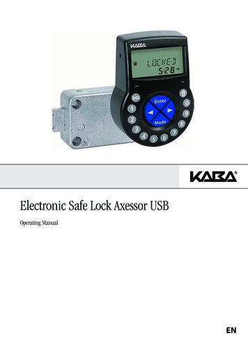
Axessor USB5Operating5.1Operating and display elements of the Input 191516171918LC-DisplayBuzzer DEL (delete, close lock) NUMERIC keys (numeric keys 0 9) LEFT key (directional key to navigate) MODE key (activate Programming Mode) RIGHT key (directional key to navigate) INFO/ESC key (activate info display or escape/go back to upper level) ENTER key (enter, confirm)Menu TIME (to set time/date)Menu PROG (to program Locking Periods)Menu DELAY (to program Time Delays)Menu CODE (to modify codes)Menu MISC (to access additional settings)Symbol „Lock open“ (unlocked) or „Lock closed“ (locked)Symbol „Replace batteries“Symbol „Warning“Time format (12/24 Hrs.)Text linesOperating ManualSubject to change without prior noticeA21-L-02-02 Axessor USB Manual EN.pdfPage 25
Axessor USB5.2Operating modes5.2.1Normal operating modeNormal operating mode for opening/closing operation. All programmed functionsare carried out, alarms will be supported and forwarded, diagnose is carried outand possible errors are displayed with a message.5.2.2Programming modeThe Programming Mode is used to alter factory set parameters and to changesettings, codes etc. Depending on the programming level, different codes arerequired.5.2.3Information menuThe information menu is accessible by pressing the INFO/ESC key while thedisplay shows “OPEN” or “LOCKED”. By repetitive pressing the INFO/ESC key or the arrow keys the individual information of the information menu can bequeried in sequence. The sequence of the information depends on whether atime lock is active or not:– Sequence, if no time lock is active: Display language Battery charge condition (in % of the nominal capacity) Opening counter Serial number Wait 000:00– Sequence, if time lock is active:Wait with hhh:mm until locking period has elapsedDisplay languageBattery charge condition (in % of the nominal capacity)Opening counterSerial numberNotes! The display language can be changed within the information menu at anytime by pressing the ENTER key (even if the lock is closed). The information menu is quitted automatically after 10 seconds without actionor can be quitted manually be pressing the DEL key.A21-L-02-02 Axessor USB Manual EN.pdfPage 26Operating ManualSubject to change without prior notice
Axessor USB5.3Buzzer signalsBuzzer signalDisplayCause1 short beepKey stroke1 short, low-frequency beepREFUSEDAction refused1 short beepevery 60 secondsWAITTime Delay or Duress TimeDelay active3 short beepsevery 60 secondsCONFConfirmation Window active(waiting for confirmation codeafter elapse of Time Delay)10 short beepsevery 10 secondsBAT-CMPOPENBattery compartment has beenopened10 short beepsevery 30 secondsOPENLock openAS 284 Programming Software Buzzer signal during „OPEN“ (lock open), during „WAIT“ (Time delay) andduring „CONF“ (Confirmation window) can be deactivated. Buzzer volume may be set to „high“, „low“ or „off“.5.4Status messagesDuring normal operation the following status messages can occur:5.4.1Locked5.4.2OpenThe lock is mechanically closed – the current time is displayed. It may be opened by entering a valid code.The lock is mechanically open. The boltwork or the safe doorcan be opened during a set period of time (factory default: 6seconds). If the boltwork is not opened, the lock automaticallycloses after the set bolt open time has elapsed.5.4.3Immediate time lockThe lock is blocked by the Immediate time lock function andcannot be opened – the current time is displayed. It may onlybe opened by entering a valid code once the set LockingPeriod has elapsed.Operating ManualSubject to change without prior noticeA21-L-02-02 Axessor USB Manual EN.pdfPage 27
Axessor USB5.4.4Time lock (Weekly)The lock is in a Weekly Locking Period and cannot beopened – the current time is displayed. It may only be openedby entering a valid code once the set Locking Period haselapsed.5.4.5Time lock (Holiday)The lock is in a Holiday Locking Period and cannot beopened – the current time is displayed. It may only be openedby entering a valid code once the set Locking Period haselapsed.5.4.6Time DelayAfter entering a valid code to open the lock the set TimeDelay starts counting – the remaining time is displayed. A„BEEP signal“ is emitted every 60 seconds. Once the counterhas elapsed, the end of the Time Delay is indicated withanother „BEEP signal“.Notes! The duration of a Time Delay may vary between the code groups. If the DEL key is pressed, the Time Delay is reset and the lock automatically returns to „LOCKED“ status. The Courier Code overrides a Time Delay if not defined differently. An input may be defined to5.4.7Confirmation after elapse of Time DelayOnce the Time Delay has elapsed, a code must be enteredagain as confirmation, within a set period of time. The remaining time allowance to enter the code is displayed.An „BEEP signal“ is emitted every 60 seconds. If the code isnot confirmed, the lock automatically returns to locked statusonce the counter reached 00:00.Notes! If the DEL key is pressed, the lock automatically returns to „LOCKED“status. If Dual Mode is activated proceed as follows in the confirmation window:Repeat two codes for confirmation, whereby the sequence is irrelevant.A21-L-02-02 Axessor USB Manual EN.pdfPage 28Operating ManualSubject to change without prior notice
Axessor USB5.4.8Enter second code (Dual Mode activated)If Dual Mode is activated, 2 codes must be entered to openthe lock. This message prompts you to enter the secondcode.Notes!Master Code and Courier Code override the Dual Mode – the lock can beopened without any additional code if not defined differently.5.4.9Penalty after wrong trialsA time penalty of 5 minutes is initiated after the fourth consecutive incorrect code is entered upon opening or accessingprogramming mode. During this period no code entries areaccepted, neither bypassing nor cancellation is possible. Theremaining penalty time is displayed.5.4.10Remote DisablingLocal opening of the lock can be disabled by a remote inputsignal (disabling signal). While Remote Disabling is activethis message is shown while the lock is closed.5.4.11Identification with denied codeCodes can be denied with a superior code, i.e. declared asinvalid until possible further re-permission. Identification witha denied code is answered with this message. The selectedfunction is not executed, the lock condition remains unchanged. This message is also displayed upon attempting toopen the lock with a Manager Code or the Master Code if therespective Code type is set to„cannot open“.Operating ManualSubject to change without prior noticeA21-L-02-02 Axessor USB Manual EN.pdfPage 29
Axessor USB5.4.12The battery compartment has been openedIf the battery compartment, which also serves as a dismounting protection for the Input Unit, has been opened. This message appears when lock is open while battery compartment is open, and when lock is locked and the battery compartment has beenopened and closed again.The message can onl
the trouble shooting of the electronic safe lock Axessor USB. 1.2.3 Limitation This Operating Manual is restricted to the installation, commissioning, operation, servicing and trouble shooting of the electronic safe lock Axessor USB. The optional AS 284 Programming Software is only described insofar as this is necessary for proper operation of .