Transcription
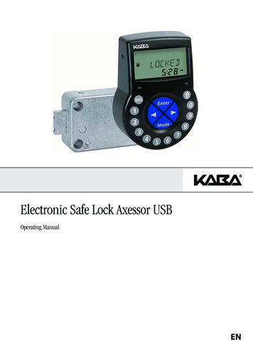
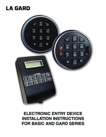
ELECTRONIC ENTRY DEVICEINSTALLATION INSTRUCTIONSFOR BASIC AND GARD SERIES
TABLE OF CONTENTSGENERAL INFORMATION 1ENTRY DEVICE MOUNTING TEMPLATES 33000 AND 3715 ENTRY DEVICE 43035 & 3125 ROUND ENTRY DEVICE 5 Swingbolt instructions Dead bolt instructions3710 ANGULAR ENTRY DEVICE 7 Additional instructions 3710 keypad replacement3750, 3750-K, 3750KE, & 3190 ENTRY DEVICE 8 Swingbolt instructions Dead bolt instructions8130 102666 KNOB ASSEMBLY 11
ELECTRONICENTRY DEVICEInstallation InstructionsGENERAL INFORMATIONIn order to maintain the highest quality standards and ensure a problem-free application, please read this guide thoroughly beforemounting the input unit. The installation instructions are the basis for Security Agency Approvals. The lock installation must be done inaccordance to these instructions in order to maintain the labeled approval level.SAFEGUARDS FOR MOUNTING1. Once an electronic lock has been mounted, no more welding can be done on the safe.2. Keep metal dust, filings, etc. away from the lock.3. Keep cables away from sharp edges and moving parts.4. Never carry keypads or locks by the cable.5. Use 9-Volt ALKALINE batteries only. The use of a high quality, name brand battery (Energizer or Duracell ) is recommended.BASIC TOOLS AND MATERIALS REQUIRED: Medium Phillips head screwdriver (#2) (recommend magnetized tip) Small flat file or deburring stone Tape measure or ruler ESD wrist bandPREPARATION FOR NEW INSTALLATION: (IF REQUIRED)1. Use the template provided to establish the exact locations (relative to the spindle hole) of the mounting holes for the Entry Deviceand the lock assembly. Be sure to consider the cable length from the entry device to the lock.2. The spindle hole diameter can be a minimum of .406" (10.3mm) to a maximum of .438" (11.1mm). The .406" (10.3mm) diameter isrecommended. Spindle hole must be deburred.3. The Entry Device mounting screws require drilled and tapped holes to 3/8" (9.5mm) depth if possible (minimum 1/4" or 6.4mmdepth required.) Drill either the two horizontal mounting holes or the two vertical holes.For Lock installation instructions, refer to 717.088 available at www.kaba-mas.com.(P/N)762.128 Rev B EN 05/10 copyright 2009-2010 Kaba Mas LLCpage 1
DIAL RING/FRONT HOUSING BASE MOUNTING TEMPLATE(P/N)762.128 Rev B EN 05/10 copyright 2009-2010 Kaba Mas LLCpage 2
8130 ENTRY DEVICES MOUNTING TEMPLATEDO NOT SCALE(P/N)762.128 Rev B EN 05/10 copyright 2009-2010 Kaba Mas LLCpage 3
3000 AND 3715 ROUND ENTRY DEVICEThe 3000 and 3715 Entry Device is designed with keyhole slots for easeof mounting and battery replacement.1. Install the two #8-32 shoulder screws (US) or the M4-0.7 shoulderscrews (metric) to mount the Entry Device to the door.2. Feed the key pad cable through the spindle cable hole from the frontof the safe door. Leave approximately 2 inches (50mm) of the cableextended out the front of the container door, to allow forbattery replacement.3. Position the Entry Device over the mounting screws and then side theEntry Device down onto the mounting screws. (Figures 1 & 2)4. Ensure that the Entry Device cable is running through the channel atthe back of the lock.37153000Keyhole SlotsFigure 1Keyhole SlotsFigure 2INSTALLING BATTERIES1. Slide the keypad housing up and carefully pull away from mounting surface to expose battery compartment.CAUTION! Hold onto the battery connector to avoid pulling the wires out of the board.2. Connect a new 9-Volt alkaline battery to the battery connector.3. Push the battery and the leads completely into the battery compartment.4. Repeat procedure for second battery ( 3000 only).5. Carefully position the keypad over the mounting screwsand slide the keypad housing down. Ensure there are no wiresor cables trapped between the Entry Device and the safe door.9 Volt Battery3000(P/N)762.128 Rev B EN 05/10 copyright 2009-2010 3715Kaba Mas LLCpage 4
3035 & 3125 ROUND ENTRY DEVICESWING BOLT1. Mount the dial plate (p/n 2676) centered on the through hole. Attach the dial platewith the two mounting screws US 8-32 (US) or the M4-0.7 (metric), and the shoulderbushings (p/n 2618).2. Slide the bearing plate (p/n 2674) over cable and press onto the fasteners on theEntry Device.3. Feed the key pad cable through the spindle cable hole from the front of the safe door.4. Insert the springs (p/n 2893) and blocking pins (p/n 2894) into the hole located on theback of the key pad.5. Rotate the key pad approx. 30 counter-clockwise and place onto the bushings. Thenturn the key pad clockwise until the blocking pin clicks, and secures the Entry Deviceto the safe door.3035 & 3125 Entry Device(Swingbolt Option)1. Key Pad2. Bearing Plate3. Mounting Screws4. Shoulder Bushing5. Dial Plate6. Spring7. Blocking Pin3125WARNING: Once installed, the Entry Device cannot be removed from the safe doorwithout causing physical damage to the Entry Device.6. When installing the lock, ensure that the Entry Device cable is running through thechannel at the back of the lock.DEAD/SPRING BOLT1. Mount the dial plate (p/n 2676) centered on the through hole. Attach the dialplate with the two mounting screws US 8-32 (US) or the M4-0.7 (metric), andthe shoulder bushings (p/n 2618).2. Measure total mounting thickness (door thickness mounting plate). (Figure 3)3. Cut the spindle to a length of .700” (17mm) plus the total mounting thickness.3035 & 3125 Entry Device(Dead Bolt/Spring Bolt Option)NOTE: the spindle must be deburred.4. Insert the spindle into the keypad, and route the cable in the groove ofthe spindle.5. Slide the bearing plate (p/n 2674) over the cable, and press onto the fastenerson the Entry Device.NOTE: It is important to make sure the cable will not rub on the dial plate afterassembly.31251. Key Pad2. Bearing Plate3. Mounting Screws4. Shoulder Bushing5. Dial Plate6. Spindle7. Cable Protector6. Feed the Entry Device’s cable and spindle through the spindle/cable hole fromthe front of the safe door.WARNING: Spring and blocking pin are NOT installed when Entry Device is used with either the dead bolt or spring bolt locks.7. Rotate the key pad approx. 30 counter-clockwise and place onto the bushings.8. Then turn the key pad clockwise until the key pad is vertical (Figure 4).Battery compartmentDOORMOUNTING PLATEFigure 3Total Mounting Thickness door thickness mounting plateFigure 4Cable protector9. The spindle should protrude between .300" - .350" (8 - 9 mm) through the safe door.10. Slide the cable protector (p/n 2754) over the cable and spindle, until the flat side rests against the inside of safe door. Route thecable through the groove of the cable protector.11. Gently pull on the cable to assure that there is no excess cable in the spindle hole that would rub on the metal door.12. Install the lock with the bolt extended onto the spindle.(P/N)762.128 Rev B EN 05/10 copyright 2009-2010 Kaba Mas LLCpage 5
INSTALLING BATTERIESThe 3035/3125 Entry Device required either a battery box (2788 or 4001), or a battery/alarm box (2789 or4002) to provide power to the lock.Mount the battery box inside the safe, and connect the cable coming from the battery box directly into theconnector port marked BAT on the lock.Small Battery and Battery/Alarm Box:1. Open safe door.2. Remove battery box cover by pulling the front portion away from the safe door.CAUTION! Hold onto the battery connector to avoid pulling the wires out of the board.2788 Small Battery Box or2789 Small Battery Alarm Box3. Connect a new 9-Volt alkaline battery to the battery connector.4. Push the battery and the leads completely into the battery compartment.5. Replace the cover and test the lock several times before closing the door.Large Battery and Battery/Alarm Box:1. Open safe door.2. Remove battery box cover by pulling the front portion away from the safe door.3. Insert six new “C” cell alkaline batteries4. Replace the cover and test the lock several times before closing the door.4001 Large Battery Box4002 Large Battery Alarm Box(P/N)762.128 Rev B EN 05/10 copyright 2009-2010 Kaba Mas LLCpage 6
3710 ANGULAR ENTRY DEVICE (ADDITIONAL INSTRUCTIONS 3716 ADAPTER)The 3710 Entry Device comes with the mylar portion of the keypad unattached.1. Feed the key pad cable through the spindle cable hole from the front of the safe door. (Figure 5).2. Position the Entry Device over the screw holes on the door, and lift the keypad to expose themounting holes.3. Install the two #8-32 screws (US) or the M4-0.7 screws (metric) to mount the Entry Device tothe door.NOTE: Ensure that the battery connector is routed through the battery open at the bottom of thehousing, and no wires are pinched under the housing.4. Remove the adhesive strip from the back of the keypad and carefully align before adhering tothe housing (Figure 6). Prior to adhering, make sure that the housing is completely free of debrissuch as filings, dust, etc., for the best possible contact.WARNING: Once installed, the Entry Device cannot be removed from the safe door without causingphysical damage to the keypad.37105. Ensure that the Entry Device cable is running through the channel at the back of the lock. Refer to lockinstallation instructions which are available at www.kaba-mas.com.Figure 5Figure 6ALTERNATE INSTALLATIONThe option adapter plate (p/n 3716) may be used to mount the 3710 Entry Device to a safe withvertical mounting hole (12 and 6 o’clock).1. Mount the adapter plate centered on the through hole. Attach the dialplate with the two mounting screws US 8-32 (US) or the M4-0.7 (metric).Then follow the above installation instructions.3716BATTERY INSTALLATION1. If installed, remove black plastic battery compartment cover (located at the bottom of the keypad) bygently pulling downward on its handle.2. Allow the battery connector and its attached leads to drop down and out of the batterycompartment. If it does not drop, gently pull on the battery connector until it does.CAUTION! Hold onto battery terminal connector to avoid pulling the wires out of housing.3. Connect a new 9-Volt alkaline battery to the battery connector.4. Push the battery and the leads completely into the battery compartment.5. Install the battery cover by placing one side of the cover in position and then pressing theother side into position with your finger.(P/N)762.128 Rev B EN 05/10 copyright 2009-2010 Kaba Mas LLCpage 7
3750, 3750-K, 3750KE, & 3190 ENTRY DEVICESWING BOLT1. Mount the dial plate (p/n 3752) centered on the through hole (Figure 6). Attach the dial plate with thetwo mounting screws US 8-32 (US) or the M4-0.7 (metric).2. Slide the bearing plate (p/n 2674) over cable and press onto the fasteners on theEntry Device (Figure 7).3. Feed the key pad cable through the spindle cable hole from the front of the safe door.4. Insert the two springs (p/n 2893) and blocking pins (p/n 2894) into the holes located on theback of the keypad (Figure 8).5. Rotate the key pad approx. 30 counter-clockwise and place keypad bushings intothe large openings on the dial plate. Then turn the key pad clockwise until theblocking pin clicks, and secures the Entry Device to the safe door.3750, 3750-KWARNING: Once installed, the Entry Device cannot be removed from the safe door without causingphysical damage to the Entry Device.6. When installing the lock, ensure that the Entry Device cable is running through thechannel at the back of the lock. Refer to lock installation instructions which areavailable at www.kaba-mas.com.3190Swing BoltMounting ScrewsPins & SpringsFigure 6(P/N)762.128 Rev B EN 05/10 copyright 2009-2010 Figure 7Insert Springs & PinsFigure 8Kaba Mas LLCpage 8
DEAD BOLT/SPRING BOLT1. Mount the dial plate (p/n 3752) centered on the through hole (Figure 6). Attach the dial plate with the two mounting screws US 8-32(US) or the M4-0.7 (metric). .2. Measure total mounting thickness (door thickness mounting plate). (Figure 9.)3. Cut the spindle to a length of 1.06” (27 mm) plus the total mounting thickness.NOTE: the spindle must be deburred .4. Insert the spindle into the keypad, and route the cable in the groove of the spindle (Figure 7).5. Route the cable either under the spindle or between the circuit board and the spindle.6. Slide the bearing plate (p/n 2674) over the cable, and press onto the fasteners on the Entry Device (Figure 7).NOTE: It is important to make sure the cable will not rub on the dial plate after assembly.7. Feed the Entry Device’s cable and spindle through the spindle/cable hole from the front of the safe door.WARNING: Spring and blocking pin are NOT installed when Entry Device is used with either the dead bolt or spring bolt locks.8. Rotate the key pad approx. 30 counter-clockwise and place keypad bushings into the9. Then turn the key pad clockwise until the key pad is vertical.10. The spindle should protrude between .300" - .350" (8 - 9 mm) through the safe door.11. Slide the cable protector (p/n 2754) over the cable and spindle, until the flat side rests against the inside of safe door. Route thecable through the groove of the cable protector.12. Gently pull on the cable to assure that there is no excess cable in the spindle hole that would rub on the metal door.13. Install the lock with the bolt extended onto the spindle. Refer to lock installation instructionswhich are available at www.kaba-mas.com.Figure 9MOUNTING PLATEDOORTotal Mounting Thickness door thickness mounting plateFigure 9Dead/Spring BoltBATTERY INSTALLATION1. If installed, remove black plastic battery compartment cover (located at the bottom of thekeypad) by gently pulling downward on its handle.2. Allow the battery connector and its attached leads to drop down and out of the batterycompartment. If it does not drop, gently pull on the battery connector until it does.CAUTION! Hold onto battery terminal connector to avoid pulling the wires out of housing.3. Connect a new 9-Volt alkaline battery to the battery connector.4. Push the battery and the leads completely into the battery compartment.5. Install the battery cover by placing one side of the cover in position and then pressing theother side into position with your finger.(P/N)762.128 Rev B EN 05/10 copyright 2009-2010 Kaba Mas LLCpage 9
8130 ENTRY DEVICEStandard methodThe 8130 Entry Device comes with a backplate with keyhole slots for ease of mounting (Figure 10).1. Locate, drill and tap holes to mount the Entry Device to the outside of the safe door using the installation template provided.2. Install the two #8-32 shoulder screws (US) or the two M4-0.7 shoulder screws (Metric) on the front of the safe door to mount theEntry Device to the door (Figure 11).3. Feed the Entry Device cable through the spindle cable hole from the front of the safe door (Figure 12).4. Position the keyhole slotted holes on the backplate of the Entry Device over the mounting screws and then slide the Entry Devicedown onto the mounting screws.5. Remove the adhesive strip from the back of the keypad and carefully align before adhering to the housing. Refer to lock installationinstructions which are available at www.kaba-mas.com.Figure 10Figure 11Figure 128130 alternate method (tamper evident for vds approval)The 8130 Entry Device comes with the mylar portion of the keypad unattached (Figure 13).1. Locate, drill and tap holes to mount the Entry Device to the outside of the safe door using theinstallation template provided.2. Feed the Entry Device cable through the spindle/cable hole from the front of the safe door.3. Install the two M4-0.7 Phillips screws through the front of the housing to mount the Entry Device tothe door (Figure 13).WARNING: 8130 Before completing the next step, you should ensure that the jumper switches fortime delay/open window are set as desired.4. Remove the adhesive strip from the back of the keypad and carefully align before adhering tothe housing.In order to use either the Dead bolt or Spring bolt locks, with Entries 3000, 3710, 3715, and 8130 amethod of retracting the bolt will be required. Knob Assembly (p/n 2666) is recommended.(P/N)762.128 Rev B EN 05/10 copyright 2009-2010 Figure 13Kaba Mas LLCpage 10
2666 KNOB ASSEMBLY2666The holes required to mount the knob need to be drilled 1.25" apart and must be centered over the spindle hole.1. To install the Knob Assembly, remove the insert from the front of the knob.2. Cut the spindle to a length of .820" (20.8mm) plus the door thickness (Figure 14).NOTE: the spindle must be deburred.3. Install the knob assembly using the two 8-32 X 5/16 phillips pan screws.4. Install the lock (with the bolt extended) onto the spindle, placing it flush to the mounting surface. Refer to lock installationinstructions which are available at www.kaba-mas.com.Figure 14MOUNTING PLATEDOORTotal Mounting Thickness door thickness mounting plate(P/N)762.128 Rev B EN 05/10 copyright 2009-2010 Kaba Mas LLCpage 11
The lock installation must be done in accordance to these instructions in order to maintain the labeled approval level. SAFEGUARDS FOR MOUNTING 1. Once an electronic lock has been mounted, no more welding can be done on the safe. 2. Keep metal dust, filings, etc. away from the lock. 3. Keep cables away from sharp edges and moving parts. 4.