Transcription
Audio Distortion Measurementsby Steve TemmeIn the never ending quest for bettersound transmission, reinforcement, andreproduction, the electronics have beenextensively analyzed for distortion. Dis tortion in the electro acoustic transduc ers, while typically several orders ofmagnitude greater, has often been ne glected or not even specified because ithas been difficult to measure and inter pret. With a basic understanding oftransducer limitations, some knowledgeof human hearing, and the applicationof different distortion test methods, electroacoustic transducer distortion be comes easier to measure and assess.VJIntroductionAll transducers have limitations, in cluding our ears. There are many waysto describe these limitations, both ob jectively through measurements, andsubjectively through personal listen ing evaluations. The goal, of course, isto correlate what we measure withwhat we hear, and so to better under stand how the transducer works. Thisin turn should help the designer tomake better performing and soundingelectro acoustic transducers faster t h a nby trial and error alone.Before looking at distortion, somefundamentals must be understood. Itis pointless to discuss nonlinear meas urements without having first per formed some linear measurements. Forexample, what is the transducer's fundamental frequency, phase, and timeresponse. These typical measurementscan tell a lot about a transducer's performance and are necessary for a better understanding of its nonlinear behaviour. But these linear measurements cannot completely describe allof the inaccuracies we hear. For exampie, people often refer to the perceived"clarity" in a long distance telephonecall or the "transparency" in a highquality loudspeaker system. It is veryunlikely that this condition can be completely explained by linear measurements alone. Nonlinear analysis aidedby distortion measurements is probably going to be more revealing as tothe limitations which most influencethis perception.In order to clarify why and how tomeasure distortion in electroacoustictransducers, information will be presented on psychoacoustics, transducermechanisms causing distortion, distortion measurements without the needfor an anechoic chamber, and standards for measuring distortion. Different test methods are discussed formeasuring random, harmonic, inter-
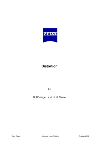
modulation, difference frequency, andtransient distortion. Practical examples of distortion measurements madeon loudspeakers, microphones, tel-ephones, and hearing aids will be presented. Of course, most of what is discussed can be equally applied to distortion measurements on other transduc-ers, electronics, and storage medias(e.g. headphones, amplifiers, tape recorders, etc.).Distortion DefinitionDistortion occurs whenever the input/output transfer function alters thewaveform of a signal, discounting noise,interference, and amplification or at tenuation (Fig. 1). Distortion can bedivided into two main categories [1].a. Linear distortion: time and fre quency dependent characteristics ofthe amplitude and phase responseof the transfer function, e.g. anideal equalizer. This occurs with nochanges in the frequency content ofthe input signal such that one fre quency at the input results in onlyone frequency at the output. , r ,.,.,. ,,b. Nonlinear distortion: changes in thefrequency content of the input sig nal such that energy is transferredfrom one frequency at the input tomore than one frequency at the out put. Nonlinear distortion productsusually have a fixed frequency rela tionship to the excitation frequency.This phenomena is usually level de pendent, e.g. clipping.For convenience, the term fundamental is defined herein as the linear por tion of the response, and distortion asthe nonlinear portion of the responseof the device under test.Fig. 1 Nonlinear transfer characteristicsFig. 2 Harmonic distortionFig. 3 Positive Peak Limited Sine wave results in Even OrderHarmonics2Fig. 4 Positive and Negative Peak Limited Sine wave results inOdd Order Harmonics
Distortion OrderDistortion can be broken down intoindividual even and odd order compo ndrdnents, for example, 2 and 3 har monic distortion products (Fig. 2).Asymmetrical system nonlinearitiescause only even order distortion products (Fig. lc). Signals, like the positivepeak limited sine wave, limited only onthe upper half-cycle (Fig. 3), containhigher amplitude even order harmon ics than odd order harmonics. Symmetrical system nonlinearities causeonly odd order distortion products (Fig.lb). Signals, like the positive andnegative limited sine wave (Fig. 4), whichwill look like a square wave if limitedenough contain higher amplitude odd, , '. .,, ,order harmonics than even order harmonies.Distortion is a relative measurement,usually referenced to the linear por tion of the output signal both in ampli tude and frequency. For example, totalharmonic distortion (THD) is usuallydescribed as a percentage of the powersum of all the harmonics to the powersum of all the harmonics plus the fun damental (i.e. amplitude normaliza tion).%THD -1 0 0 V g 2 2 HiHf Hi HlFig5a Simli ied'P frepresentation of a transducer with a limited frequencyrange and ardpeak at 1 kHz. Fundamental response (HJ, 2nd harmonic (HJ and 3 harmonic (HJ of20 Hz -HiHN Harmonic response ofthN harmonic.H1 Fundamental response.The distortion response is usually plotted under the corresponding excitation frequency of the measured funda mental response (i.e. frequency nor ndmalization). For example, the 2 har monic of 20 Hz occurs at 40 Hz and therd3 harmonic occurs at 60 Hz (Fig. 5a).Instead of plotting the harmonic dis tortion products at their actual meas ured frequency (Fig. 5b), their valuesare plotted at their excitation frequency(Fig. 5c). This can lead to some difficul ties in evaluation due to the influencethat the passband and shape of thefundamental response have on the dis tortion responses. For example, a peakat 1 kHz in the fundamental responsendwill show up as a peak in the 2 har monic response at 1/2 the frequencyrdand 1/3 the frequency for the 3 har monic response (Fig. 5c). When following this convention it is easy to misin terpret the relative distortion level.Typically when viewing such a graphas in Fig. 5c, it is the difference in thelevel that is observed between the distortion and the fundamental at a parrdticular frequency (see Fig. 5c.: 3 Har-Fig. 5b Distortion Responses at the Actual Measured Frequencies (assuming 100%constant distortion vs. frequency)Fig. 5c Distortion Responses frequency normalized to the Fundamental Responsemonic at 20 Hz). This explains whyharmonic components can appear tobe higher in level than the fundamental at the low end of the frequency scaleand lower in level at the high end of thefrequency scale. Significantly different results will be obtained if the responses in Fig. 5b and 5c are used tocompute THD.3
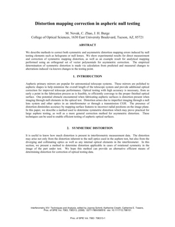
PsychoacousticsThe human ear's sensitivity to soundvaries with frequency and level.Fletcher-Munson loudness curves de scribe this relationship. These curvesindicate that tones at the low and highfrequency end of the audio band areless audible than tones of the sameamplitude in the middle frequencyband. This also applies to distortionproducts. For example, Moir found thatharmonic distortion below 400 Hz be came increasingly harder to detect thanharmonic distortion above 400 Hz [2].Distortion audibility is also a func tion of sound duration. The ear has afinite time resolution. Moir has foundthat distortion due to clipping of a 4millisecond tone burst reached about10% before it was detectable, but in creasing the pulse length to 20 miiliseconds reduced the "just detectable"distortion point to around 0.3% [21.Another important psychoacousticphenomena is masking. Sounds in ourenvironment rarely occur in isolationas pure tones. The study of masking isconcerned with the interaction ofsounds. Tonal masking, for instance,deals with the change in the percep tion threshold for a particular tone inthe presence of another tone (Fig. 6).Narrow band noise is used instead of apure tone for the masking frequency inorder to reduce "beating", low frequencymodulation, when the probe tone ap proaches the same frequency of themasking tone. Fig. 6 indicates thatmore masking occurs for frequenciesabove the masking tone than below [3].This becomes significant when discuss ing the audibility of different kinds ofdistortion.In the case of harmonic distortion,ndthe fundamental masks the 2 har rdmonic component more than the 3harmonic and very little for the higherharmonic components. This is anotherfrequency and level dependent phe nomena. The masking threshold wid ens in the low and high frequency endof the audio band and with increasingsound pressure level.4 Q Masking threshold for a pure tone in the presence of narrow band noise centred ati kHz (Zwicker, 1975). For a masking tone of 100 dB SPL, the 2nd Harmonic is maskedfor levels below 70 dB and the 3rd Harmonic is masked for levels below 60 dB SPL -7Middle C (261.63 Hz) played by a Flute
The harmonic structure of musicalinstruments may also mask harmonicdistortion products. The amount ofmasking will vary depending on thetype of instrument and music.For example the flute (Fig. 7) hasfewer and relatively lower harmonicsthan the guitar (Fig. 8). The flutesounds more "pure" while the guitarsounds more "rich". Consequently, har monic distortion introduced by a loud speaker when reproducing guitar mu sic will be harder to detect than whenreproducing flute music.Some people think that vacuum tubeelectronics also sound pleasingly "rich"or "warm". Their nonlinearity, typi cally more asymmetric than symmet ric, occurs more gradually with levelthan most transistors and results insofter clipping. Therefore, they mayndhave relatively high 2 order distor tion but very little high order distor tion. Furthermore, even order distor tion, especially integer multiples2,4,8,16., coincides with perfect oc tave intervals on the musical scale. Soadding a certain amount of even orderdistortion to the original music signalis generally quite tolerable and some times even pleasant.Odd order distortion, resulting fromsymmetrical clipping, for example, gen erally sounds "fuzzy" and "grainy". Thehuman ear is not very tolerant to thiskind of distortion. In fact the harderthe clipping, the greater the number ofhigher order harmonics. At some point,probably above the 15th harmonic,these high frequency components be gin to sound separate from the funda mental. They become two distinctsounds. A defective rubbing voice coilin a loudspeaker is a good example ofthis.A "rub and buzz" measurement isperformed by placing the microphonein the nearfield of the loudspeaker, asnear to the loudspeaker cone as possi ble, to achieve the best signal to noiseratio (Fig. 9). The excitation frequencyshould be near or at the loudspeaker'sresonant frequency and at as high alevel as possible to achieve maximumcone excursion.Fig. 8 Middle C (261.63 Hz) played by a classical GuitarFig. 9 Measurement setup for Rub and Buzz measurement on a loudspeaker5
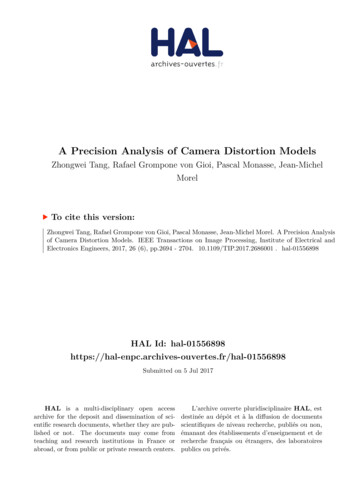
The significant difference betweenthe two loudspeakers in Fig. 10, is thedramatic rise in the level of harmonicsabove the 12th harmonic. High orderharmonics as low as 60 dB below thefundamental can be quite audible [4].This is probably in part due to the largeshift in frequency from the fundamen tal and the region in which these highorder harmonics fall, outside the mask ing region and typically in the ear'smost sensitive frequency range.Notice that in the "good" loudspeaker(Fig. 10a), the total harmonic distor tion is actually higher t h a n t h a t for the"bad" (Fig. 10b), buzzing loudspeaker.ndrdThis is because the 2 and 3 har monic components dominate in levelcompared with the high order harmon ics. Therefore, measuring just totalharmonic distortion is clearly notenough to completely describe the non linear behaviour of an electroacoustictransducer. Therefore, to detect ruband buzz it is necessary to measurehigh order distortion products inde pendent of both low order distortionproducts and background noise.Fig. 10 Resulting spectrum for a pure tone excitation (f) at 200 Hza) Upper curve shows a distortion spectrum of a normally functioning loudspeaker.THD 6%b) Lower curve shows a distortion spectrum containing high order harmonics resultingfrom a "rubbing" voice coil caused by a bent frame. THD 2%Transducer Mechanisms Causing DistortionAll electroacoustic transducers possesssome asymmetrical nonlinearities.This could be due to an asymmetricm a g n e t i c or electric field whosestrength changes with diaphragm po sition. Electrostatic transducers, suchas condenser microphones, are usuallypolarized with a single fixed electrode.Consequently, the electric field be comes stronger as t h e d i a p h r a g mmoves closer to the electrode. Dynamicor moving-coil transducers, such asmost loudspeakers, typically have anasymmetrical magnetic field, due tothe geometry of the pole piece, causingthe force on the voice coil to changewith position (Fig. 11 a). When the voicecoil is in its upper position, there isvery little of the pole piece inside it. Inits lower position, the pole piece acts asan iron core, thus raising self-induc tion. This alternating magnetizationof the pole piece and asymmetricalforce create self-induction distortionand hysteresis distortion.Therefore, even order distortionproducts, especially at low frequencieswhere the displacement is greater,6Fig. 11a Cross section of a loudspeaker "motor" with a "short-circuiting ring"should indicate these asymmetricalnonlinearities. A good example of howa loudspeaker manufacturer reducedthis kind of distortion by adding a"short-circuiting ring" to counter balance some of t h e s e a s y m m e t r i c a l
nonlinearities, can be seen in Fig. l i b[5].All electroacoustic transducers alsopossess some symmetrical nonlineari ties. This could be the result of physi cal limits on the diaphragm's displace ment or an actual limiting circuit suchas found in telephones to prevent hear ing damage from excessively loud sig nals. So, odd order distortion productsshould indicate these symmetric nonlinearities. For example, when a voicecoil approaches the physical excursionlimits of the motor system. Again atlow frequencies, where the displace ment becomes greater, odd order dis tortion products should increase (Fig.lie).It is interesting to note t h a t in theprocess of reducing asymmetrical dis tortion, with the short circuiting ring,rdsome symmetrical distortion, 3 har monic, was reduced as well.ndrdMeasuring the 2 , 3 , and higherharmonics of a transducer can be vervrevealing as to some of the design prob,. ., ,.,lems, but as already discussed, someharmonic distortion produced by thetransducer may not be especially dis pleasing nor audible. Third harmonicdistortion in a tweeter, for example, at10 kHz occurs at 30 kHz. Clearly, thedistortion present at 30 kHz is notaudible, but it still represents a prob lem. So what significance should beplaced on harmonic distortion prod ucts? How and what levels are clearlyobjectionable, and are there any otherways t h a t distortion can be producedt h a t might be more objectionable?In the hope of answering these ques tions, different distortion test methodsneed to be discussed with respect to;How well do they simulate real operat ing conditions? Can they be correlatedwith each other and perceived distor tion audibility? How easy are they tounderstand and perform?Fig. lib 2nd Harmonic Distortion reduced by the addition ofan aluminium (AL) shortcircuiting ring in the woofer's motor. Measured in an anechoic chamber at 40 cm, 104 dB1 kHzto1terrf%J?* '*f "Pjvalent«? f *?SPL. (IEC Graph Standard87263 — same 25 dB/decade as in rig. 27 using B&K chart paper)Fig. lie 3rd Harmonic Distortion with the addition of an aluminium short-circuitingring in the woofer's motor7
Distortion Test MethodsIt is possible to make theoretical mod els for some of the nonlinear behaviourin transducers. But, under real operat ing conditions, transducers and theirassociated electronics also exhibit nonlinearities which are very difficult tomodel. This could be distortion due toabrupt or temporal changes in the in put/output characteristics, such asthermal effects, saturation, and me chanical fatigue. Capacitors, inductors,springs, and dampers all possess someof these nonlinearities. Consequently,the best solution and maybe the onlysolution, in this case, is to measuredistortion with the best tools avail able. This has always been very diffi cult for two main reasons: First, from apractical point of view, the question ofhow to separate out the distortion prod ucts while at the same time simulatingreal operating conditions; Second, theproblem of getting instrumentation toperform tests quickly and accurately.Real operating conditions vary fromapplication to application. For exam ple, the spectral content and energy ofspeech is very different from that ofmusic. Therefore, maybe different testsignals should be used for telephonetesting as compared to loudspeakersdesigned for listening to music. Mostnatural sounds including speech andmusic are continuously changing.Therefore, real world signals tend to betransient, and contain many simulta neous frequencies like a pulse (Fig.12).The problem is how to isolate distor tion products from the fundamentalresponse and noise.Fig. 12 A Pulse and its Frequency SpectrumRandom Distortion (RD)One way to isolate the distortion prod ucts and still use a broadband testsignal is to measure the coherence be tween the input and the output signal.This can be performed by using a twochannel signal analyzer that can meas ure the coherent and noncoherentpower of the device under test, forP ' iP iCoherent power is the part of thedevice's output spectrum which is lin early related to the input, while non coherent power is the remainder. Noncoherence can be caused by distortion,noise, leakage or resolution bias errors, and uncompensated group delays. But with careful measurementprocedure, some of these factors can beeliminated or reduced so that distortion is t h e d o m i n a n t factor fornoncoherence. A more thorough de-8Fig- 13 Measurement setup for 2-Channel measurement on Hearing Aidss crip tion of this technique can be foundin reference [6].Measurements on hearing aids withcompressor circuits are particularlydifficult to perform because they usually contain a microphone, an amplifier with signal processing, and a loudspeaker. Their response, like the ear,changes depending on the level andfrequency content of the signal whichis applied. The family of curves in Fig.14a accurately represents the devicewhen the input is a sine wave. Buthearing aids are made to be used withcomplex signals such as speech ormusic. The sine result may not realis-
tically represent this intended use.One way to measure distortion witha more realistic test signal, is to userandom noise with a speech-shapedspectrum and measure the ratio of thenoncoherent to coherent power (Fig.14b). Notice how the shape of the re sponse is different from the sine test inFig. 14a.While this provides a reasonable ap proximation of real world operatingconditions, the end result is total random distortion. Since the device undertest is simultaneously being stimu lated across its entire frequency range,there is no way to identify the type ofdistortion at a particular frequency.H a r m o n i c D i s t o r t i o n (HD)It turns out t h a t the simplest and mostpractical way to separate out the indi vidual distortion components from thelinear response is to use a sine wave asthe excitation signal Since distortion,j ,.n jis very level dependent, using a sinewave as the test signal makes inter preting input and output levels verystraightforward. By sweeping the sinewave, the individual harmonic distor tion components can be measured witha tracking filter so t h a t individual har monic distortion versus frequency canbe measured (Fig. 15a). Also noise willbe largely attenuated. Using a notchfilter (Fig. 15b) t h a t only attenuatesthe fundamental and measures every thing else will include not only totalharmonic distortion but noise as well.Noise in the case of electroacoustictransducer measurements is usuallyentirely due to background noise sincetransducers inherently have no self,i,.minoise. The one noticeable exception arehearing aids which have built-in elec tronics. Also it is common for the back ground noise to be higher t h a n theelectroacoustic transducer's distortion.Because electroacoustic transducersusually have a nonflat response with alimited frequency range as was shownin Fig. 5. results for distortion meas urements, especially for harmonic dis tortion can be misleading and difficultto correlate with perceived distortion.The transducer's fundamental re sponse can be viewed as a linear filterwhich is independent of the transduc er's nonlinearities. This linear filterwill alter the shape of the distortionresponse. Consequently, this can leadto an underestimation of the true dis tortion, especially at the transducer'shigh frequency limit, (i.e. above 1/3 therdupper cutoff frequency for the 3 harmonic). This can also lead to overestimations of the true distortion, espe-F S- 14a Hearing aid with a varying response due to its built-in compressor. Frequencyresponse measured with stepped sine stimulus from 50 - 90 dB input level in 2 dBincrementsFi14eren am \' l' *Noncoherent Power output of a hearing aid measured using a 2channel bb 1 analysis. Speech-weighted noise stimulus at 70 dB input levelaFig- l& Total Harmonic Distortion (THD) measured with a "tracking" filter (includesselected distortion components)9
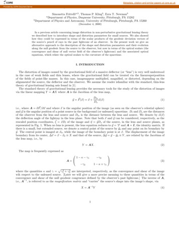
cially at the lower frequency limit.When reading a distortion responsegraph, it is important to keep in mindat what frequencies are the distortionproducts actually occurring and howdoes this level compare to the level ofthe fundamental at the excitation frequency.Two-Tone Interaction DistortionAn interesting alternative to harmonicdistortion is to use two test tones andmeasure intermodulation distortion.Intermodulation distortion resultswhen signals with more than one frequency interact to produce frequencycomponents not found in the originalsignal. In practice, system nonlinearities cause intermodulation distortion(IM) to occur due to amplitude and/orfrequency modulation of the higherfrequency components by the lowerfrequency components [7].This is a more reasonable approxi mation of a real world signal. Meas urements with more than two test tonesare possible, but interpreting resultsbecome unmanageable and too com plex. Although intermodulation dis tortion requires two signal generators,the purity of the signal generators isnot as important as with harmonicdistortion measurements since themeasured intermodulation compo nents do not correspond with the harmonies of the individual signal generators.This is illustrated in Fig. 16a wheretwo sine waves at 100 Hz and 800 Hzare simultaneously introduced into anonlinear system. The resulting signalcontains distortion components whichare sidebands around 800 Hz. The fre quencies of the sidebands are equal tothe sum and difference of the upperfrequency (800 Hz) and the integermultiples of the lower frequency: 800Hz /-100 Hz, 800 Hz /- 200 Hz, 800Hz /- 300 Hz, and so on.Difference frequency distortion (Fig.16b) is a special case of intermodula tion distortion which only considerscomponents which are the differenceand multiples of the difference betweenthe excitation frequencies. IM distor tion considers both sum and differencecomponents.Distortion order is used to describethe frequency relationship of a givendistortion component to the input signal. For harmonic distortion, distortion order is equal to the harmonicnumber. For intermodulation distortion and difference frequency distortion, distortion order is equal to thesum of the absolute value of the fre-10A/ otch\R t e r a t Fundamental/\/\/ -\/\/00veral1 noise level 4 /I r A/y .IWIMAA 'VWJJ WWA- / ievei rrI IvW tii\fl/V\fi/w\e1II(U" 20 kHz f(iin) *920348e - 1CU mrrn -KTJ -,L « u» ru r 1 ,J7 7 - 7 / 1tig. 15b 1HD N measured with a notch fitter (mctudes overall noise level)iuustrationHz input signalFig16a0fIMdistortion resulting from the interaction of a 100 Hz and 800Fig. 16b Difference frequency distortion resulting from a 800 Hz and 900 Hz inputsignalquency coefficients (Fig. 17a and b). Anegative distortion order means thatthe measured distortion componentfalls below the higher of the two testtones.Example: - 3 IMThe distortion order offj - 2f 2 (Fig. 16a) is111 - 1-21 3rd orderdistortion productPositive even order difference frequency distortion products are equivalent to their negative even order counter parts, except that they occur atnegative frequencies and are, therefore, not measured.It is important to be careful not tomeasure too low in frequency wherethe measured distortion componentfalls either too close to DC or one of the
test tones. Also, it is important not toinadvertently measure at harmonicmultiples of the test tones. This willinclude unwanted harmonic distortioncomponents. A good rule of thumb is tomeasure more than N times above thefixed tone (f2) for IM distortion. For DFdistortion measure more than N timesabove the delta frequency (f: - f2). N isthe greatest absolute value of the nega tive distortion order.Example: - 3 DFIf A f f 1 - f 2 1 0 0 H zwhenf2 100 Hzandfx 200 Hzthen 2f 2 -lf 1 0 Hzso the frequency sweepshould start aboveI-3 I-100 Hz 300 HzSince music and speech consist of manydifferent frequencies occurring simul taneously, the distortion test signalused should also contain more thanjust one frequency. This provides anopportunity to see how the systemcauses interaction between the vari ous frequency components. A singletone cannot be used to measure interaction phenomena, such as a full rangetransducer might cause when repro ducing a broadband signal. Further more, the sum and difference compo nents arising in two-tone interactiondistortion have no harmonic musicalrelationships and hence can be quiteannoying. The difference components,in particular, are unlikely to be maskedby the two test tones since they appearat lower frequencies, outside the effec tive masking curve region as was shownin Fig. 6.Another advantage of two-tone in teraction distortion measurements isthat they can be used over the entirefrequency range of the system, whereasharmonic distortion measurementsbecome meaningless when the distor tion products approach the system'sfrequency limits.Practical examples of DifferenceFrequency Distortion (DFD) measurementsAll transducers, including our ears,have some kind of frequency limits.Even the measurement equipmentused to measure the transducer undertesthasfrequencylimits(e.g.theBruel& Kjaer Type 4133 measurement microphone rolls offabove 40 kHz). So thegoal is to get the distortion componentsto fall in the passband where they arenot attenuated and can be measured(Fig. 18).Forelectroacoustictransduc-Fig. 17a IM distortion order definitionF&17hDFdistortion order definition ig. }g Harmonic distortion components are attenuated by the high frequency roll-off ofthe system, while difference frequency distortion components remain inside the passbandof the system (assuming 100% distortion)ers, this usually corresponds to peopie's hearing range, as well.A transmit measurement on a telephone is a classic example of abandlimited device (Fig. 19). The telephone interface provides the desiredline loading and DC powering whilethe artificial mouth and ear simulatereal operating conditions.Note the way that the -2 differencefrequency distortion rises with frequencyinFig. 20. This is probably dueto the limited maximum current delivered to the telephone line. Government regulations require a limit toprevent saturation or line loading.11
Notice how at the higher frequencies,ndthe measured 2 harmonic distortionndunderestimates the true 2 order dis tortion due to the steep roll off which isactually desired because of the tel ephone line's limited t r a n s m i s s i o nbandwidth. If one were to judge thequality of this telephone based on thendmeasured 2 harmonic distortion at 5kHz, one might think t h a t 1 % (-40 dB)distortion was inaudible. But in real ndity, the 2 order distortion as meas ured by the -2 difference frequencywould indicate 32% (-10 dB) distortionat 5 kHz and probably is very audible.This is true both for transducer highfrequency limitations and for electronicfiltering which also imposes a highand/or low frequency limit. For exam ple, a two-way loudspeaker system con sisting of a low frequency woofer, acrossover filter network, and a highfrequency tweeter (Fig. 21a).As can be seen in Fig. 21b, there is anrdincrease in level of the 3 harmonicdistortion from approximately 8001000 Hz. This region actually corre sponds to the crossover frequency re gion around 3 kHz ( 3 x 1 kHz). Above 1rdkHz the 3 harmonic is greatly attenu ated by the crossover filter. In com rdparison, notice how the 3 order differ ence frequency distortion increases inthe crossover frequency region. Thereis a substantial peak in the response ofthe -3 difference frequency curve at thecrossover frequency of 3 kHz. Thisclearly indicates a problem with thecrossover design t h a t might have beenrdoverlooked if only inspecting the 3harmonic distortion. In this case, abipolar electrolytic capacitor was usedin the design and its voltage rating wasexceeded causing it to saturate.Practical e x a m p l e s of Intermodul a t i o n D i s t o r t i o n (IMD) m e a s u r e mentsIntermodulation distortion can also beused effectively to evaluate crossoverdesigns. If a transducer is excited witha fixed low frequency test tone, forexample near resonance to cause largediaphragm excursions, and anothertest tone t h a t sweeps up in fre
sound transmission, reinforcement, and reproduction, the electronics have been extensively analyzed for distortion. Dis tortion in the electro acoustic transduc ers, while typically several orders of magnitude greater, has often been ne glected or not even specified because it has been difficult to measure and inter pret.