Transcription
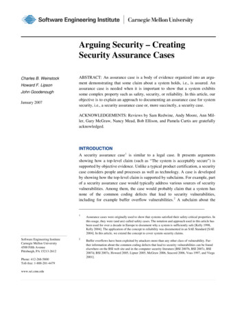
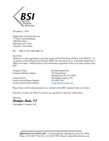
BSI Engineering, Inc.Civil & Subsurface Utility EngineersHaley and Aldridge465 Medford Street, Suite 2200Boston, MA 02129-1400Tel: (617)-886-7338Fax: (617)-886-1638November 18, 2013Project: Woburn IPLEX ProjectSubject: Subsurface Utility Engineering – CCTV InvestigationBSIE Job # 13-2830Attn: Mark Kelley, P.E.Dear Mr. Kelley,BSIE is pleased to provide the following report as per your request:CCTV INVESTIGATION OFWoburn IPLEX – Woburn, MAIntroductionBSI Engineering, Inc. conducted a CCTV investigation of sanitary sewer system at the Woburn IPLEX site in Woburn,MA. Two 30” RCP sewer interceptors ran parallel through the project limits, tying into one 30” MWRA owned andoperated system. The point of tie-in occurred in SMH 102. BSI Engineering, Inc. inspected the aforementioned sanitarysewer system and the eight associated sewer manholes. A site plan can be found attached detailing manhole numbers,location and configuration of the system. All manholes inspected will be referenced using the numbering system providedto BSI engineering found in attached site plan.Investigation Results1. SMH-104 to SMH-105 to SMH-109Utility: 30” RCP Sanitary SewerVideo: Disc 1, Title: Woburn IPLEX SMH 104-109Comments: This pipe inspection was performed upstream due to limited accessibility. Video inspection begins in SMH104 and heads north, travelling through SMH 105 and continuing to SMH 109.The pipe inspected is deemed to be in fullyoperational condition. No cracks, slipped joints or root infiltrations were discovered.Figure 1.0 SMH 105 – Top viewFigure 2.0 – SMH 105 Interior ViewClient: Haley & AldridgeJob # 13-283011/18/2013Page 1 of 4 *623707*SEMS Doc ID 623707
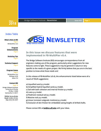
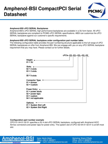
2. SMH-104 to SMH-102Video: Disc 1, Title: Woburn IPLEX SMH 104-102Utility: 30” RCP Sanitary SewerComments: The pipe inspected is the 30” RCP connecting the reading sewer line to the MWRA sewer line. This shortrun connects SMH 104 to SMH 102. A dye test was performed to confirm the connectivity of these two systems.Midway through the pipe a substantial amount of debris was encountered; due to flow levels the debris could not beidentified. The disruption of flow due to the debris can be seen below in figure 4.0.Figure 3.0 – SMH 104 Top ViewNote:DebrisFigure 4.0 – Debris EncounteredTable 1.0 – Notable CCTV Results (SMH 104 - SMH102)Distance:Clock face Orientation:4’6:003. SMH-102 to SMH 108 to SMH-110Visual:Figure 4.0Video: Disc 1, Title: Woburn IPLEX SMH 102-110Utility: 30” RCP SewerComments: This pipe inspection began in SMH 102, the first point at which the Reading system ties into the MWRAsystem. This inspection travels downstream (South), through SMH 108 and concludes in SMH 110. With the exceptionof possible debris build-up (figure 7.0) the pipe is fully operational. No cracks, slipped joints or root infiltrations werediscovered.Figure 5.0 – SMH 110 Top ViewFigure 6.0 – SMH 102 Top ViewClient: Haley & AldridgeJob # 13-283011/18/2013Page 2 of 4
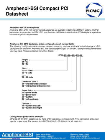
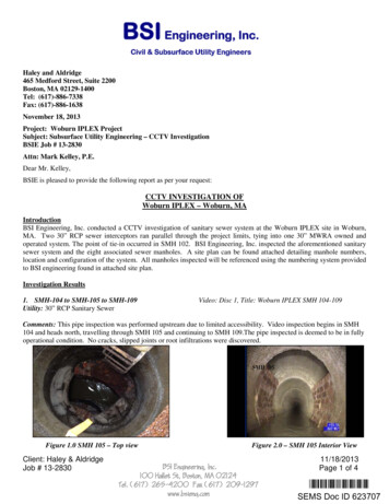
Note:DebrisTable 2.0 - Notable CCTV Results (SMH 102 - SMH110)Distance:Clock face Orientation:191’6:00Figure 7.0 – Potential Debris EncounteredVisual:Figure 7.0Figure 8.0 SMH 108 – Top View4. SMH-106 to SMH-102Video: Disc 1, Title: Woburn IPLEX SMH 106-102Utility: 30” RCP Sanitary SewerComments: This pipe inspection began at SMH 106 and travelled downstream towards SMH 102. A buried manhole wasdiscovered approximately 18’ from SMH 106. This structure was survey located by BSI. Minor debris was encountered(figure 10.0); otherwise this section of pipe has no noticeable cracks, slipped joints or root infiltration. The pipe is fullyoperational.Figure 9.0 - SMH 106 – Top ViewFigure 10.0 – Debris encounteredFigure 11.0 – Buried Structure FoundFigure 11.0 – Buried Structure locatedClient: Haley & AldridgeJob # 13-283011/18/2013Page 3 of 4
Note:DebrisBuried StructureTable 3.0 - Notable CCTV Results (SMH 106 - SMH102)Distance:Clock face Orientation:82’6:0018’N/A5. SMH-110Visual:Figure 10.0Figure 11.0Video: Disc 1, Title: Woburn IPLEX SMH 110 – Project LimitsUtility: 6” VCP Sanitary SewerComments: This section of CCTV inspection travels from SMH 110 extending past the project limits. Due to substantialdebris 327’ from SMH 110 (figure 12.0) we were not able to progress to the next structure. The pipe is in good condition,no cracks, slipped joints or root infiltrations were discovered.Figure 12.0 – Debris encounteredNote:DebrisFigure 13.0 SMH 110 – Top viewTABLE 4.0 - Notable CCTV Results (SMH 110 - Limits)Distance:Clock face Orientation:327’6:00Visual:Figure 12.0If you have any questions or concerns regarding this report, please do not hesitate to contact me at 617-265-4200 orgryan@bsieng.com.George RyanSubsurface Utility EngineerClient: Haley & AldridgeJob # 13-283011/18/2013Page 4 of 4
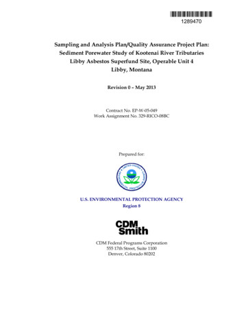
PARTIAL UTILITY SURVEYWOBURN IPLEX PROJECTWOBURN, MAPREPARED FORHALEY & ALDRICH INC.465 MEDFORD STREETSUITE 2200BOSTON, MA 02129PROJECT AREALOCUS PLANNOT TO SCALEREV.NO.DATEDESCRIPTIONMADEBYCHK.BYAPPD.BYBSI Engineering, Inc.100 Hallet Street, Boston, MA 02124Telephone (617) 265 4200 Fax (617) 209 1297 www.bsieng.comBSI ENGINEERING, INC.100 HALLET ST, BOSTON, MA 02124617 265 4200INDEX OF SHEETSSHEET NO.COVER - C1LEGEND & NOTES - L1SUEPLAN123SUBSURFACE UTILITY ENGINEERINGPARTIAL UTILITY SURVEYWOBURN IPLEX PROJECTWOBURN, MAOWNER:November 15, 2013PREPARED FORHALEY & ALDRICH INC.465 MEDFORD STREETSUITE 2200BOSTON, MA 02129IPEXMWRATOWN OF READINGBSIE PLAN NO.: 13-2830FILE: 13-2830UTIL01.DWGSUE BY: DOC/GRDRAWN BY: DOCCHKD.: GRAPPROVED: GRDATE: 11/15/2013SCALE: NTSCONTRACT NO.:SHEET NO.:1 OF 3
BSIE LEGENDQUALITY LEVEL "A" INFORMATIONTP-1QUALITY LEVEL "D" INFORMATIONVACUUM EXCAVATION DATA POINT QL-AQUALITY LEVEL "B" INFORMATIONCS QL-BCOMBINED SEWER QL-BCTV QL-BCABLE TELEVISION QL-BSD QL-BDRAIN QL-BE QL-BELECTRICAL QL-BFA QL-BFIRE ALARM QL-BG QL-BGAS QL-BS QL-BSEWER QL-BST QL-BSTEAM QL-BT QL-BTELECOMMUNICATIONS QL-BTR QL-BTRAFFIC QL-BUAIR QL-BUNDERGROUND AIR PRODUCTS QL-B: CO2, NO2, ETC.U QL-BUNKNOWN TRACE SIGNAL QL-BW QL-BWATER QL-BCS QL-DCOMBINED SEWER QL-DCTV QL-DCABLE TELEVISION QL-DSD QL-DDRAIN QL-DE QL-DELECTRICAL QL-DFA QL-DFIRE ALARM QL-DG QL-DGAS QL-DS QL-DSEWER QL-DST QL-DSTEAM QL-DT QL-DTELECOMMUNICATIONS QL-DTR QL-DTRAFFIC QL-DUAIR QL-DUNDERGROUND AIR PRODUCTS QL-D: CO2, NO2, ETC.W QL-DWATER QL-DLAND BASEEXISTING BUILDINGS & RELATED STRUCTURESBRIDGE ABUTMENTSQUALITY LEVEL "C" INFORMATIONMAJOR CONTOURCS QL-CCOMBINED SEWER QL-CCTV QL-CCABLE TELEVISION QL-CSD QL-CDRAIN QL-CE QL-CELECTRICAL QL-CFA QL-CFIRE ALARM QL-CG QL-CGAS QL-CS QL-CSEWER QL-CST QL-CSTEAM QL-CT QL-CTELECOMMUNICATIONS QL-CTR QL-CTRAFFIC QL-CUAIR QL-CUNDERGROUND AIR PRODUCTS QL-C: CO2, NO2, ETC.RECORD INFORMATIONU QL-CUNKNOWN TRACE SIGNAL QL-CCHANGE IN QUALITY LEVELW QL-CWATER QL-CSUE PROJECT LIMITSMIINOR CONTOURMISC. DETAILS / EDGE OF PAVEMENTCHAINLINK OR WOOD FENCESTEEL GUARD RAIL OR ROT IRON FENCEPROPERTY LINETOP OF CURBS / BACK OF SIDEWALKSRETAINING / STONE WALLSSUE PLAN NOMENCLATUREOROVERHEAD ELECTRIC - TELEPHONE - CABLEEND OF INFORMATIONIRON PIPEOVERHEAD ELECTRIC - TELEPHONECAST IRONOVERHEAD ELECTRIC - CABLESEWER FORCE MAINSALT WATEROVERHEAD CABLEHOT WATERPOLICE DEPARTMENT FACILITIESPPBBMBENCH MARKBNDSTONE BOUNDCATCAT CONTROL POINT1. Certain utilities shown have been traced on the ground using electronic designation techniques.Designation, or electronic utility location, is defined as the surface location of a utility line basedon electronic geophysical prospecting techniques and is approximate in relation to the actuallocation of the possible utility.2. Certain utilities shown have been taken from available record information. These utilities maynot have been verified. (See Note #4 below.)3. All existing designated utilities near proposed construction should be exactly located usingNon-Destructive Air-Vacuum Excavation, if not already located by Air-Vacuum Excavation (SeeQuality Level A above).4. Unless Non-Destructive Air-Vacuum Excavation is utilized at a particular location, BSIE doesnot guarantee the existence or non-existance of utility lines5. At locations, where BSIE is directed to perform Non-Destructive Air-Vacuum Excavation, thetest hole is advanced until a condition of practical refusal for Air-Vacuum Excavation is reachedor hole is advanced to a depth of 8.0' (eight feet). Practical refusal being defined as encounteringa utility, bedrock, water table, large rocks/ cobbles, suspected hazardous materials or a conditionof hole instability.6. Where BSIE is directed to perform Non-Destructive Air-Vacuum Excavation to confirm thenon-existance of utilities, BSIE will only report non-existance of utilities within the visible limitsof the excavation. BSIE is not responsible for ensuring that work by others is performed at thesame location as the Air-Vacuum Excavation Hole.7. Below ground structures unless otherwise depicted are symbolic only.8. Prior to any excavating, BSIE recommends that all utility owners should review this drawingfor accuracy and completeness.SEWER FACILITIESDCCATCH BASIN ROUNDSSEWER MANHOLELDRAIN LEACHING BASINELECTRICAL FACILITIESEHHEMPEC BOXELHSCCCROSS CUTGeneral Project Notes:DHDRILL HOLEIPIRON PIPELPLEAD PLUG W/ BRASS TAC1. Mapping provided by:Haley & Aldrich Inc.465 Medford StreetSuite 2200, Boston Ma 021292. Horizontal and vertical survey control provided by:Haley & Aldrich Inc.465 Medford StreetSuite 2200, Boston Ma 02129TELEPHONE MANHOLETTELEPHONE CABINETTELBFDFFIRE PULL BOXFIRE MANHOLEGAS DIVISION GATEGGGAS GATE CIRCULARGGSPGAS GATE SERVICE PIPEGMPGRPUNKNOWN FACILITIESUNKNOWN GATE VALVEMHUGSAGGTBGAS SACRIFICIAL ANODEGAS TEST BOXGAS VENTACBVHYDHYDSEWERSTEAMUNKNOWNUNDERGROND AIRABANDONEDCHIMNEYBOTTOM OF MH STRUCTURENOTE CALLOUTREV.NO.DATEWATER DIVISION GATEWATER GATEWGFPWATER GATE FIRE PIPEWTBOWNER:WATER GATE SERVICE PIPEWGSPWATER SACRIFICAL ANODEWATER TEST BOXSTEAM REGULATOR PITAPPD.BYPARTIAL UTILITY SURVEYWOBURN IPLEX PROJECTWOBURN, MAWATER STAND PIPEWGCHK.BYSUBSURFACE UTILITY ENGINEERINGWATER POST INDICATOR VALVEDIV. GATEMADEBY100 Hallet Street, Boston, MA 02124Telephone (617) 265 4200 Fax (617) 209 1297 www.bsieng.comWATER PITOMETERPIVDESCRIPTIONBSI Engineering, Inc.WATER METER PITPTGAS GATE SQUARESTEAM VALVEWATER CHECK VALVEFIRE HYDRANTWMPGGSTVPARKER KALON NAILWATERAIR COCKLOWRY HYDRANTWSASTEAM MANHOLEMASS. GEODETIC DISKELECTRICBUTTERFLY VALVECHK. VALVEGAS DRIPSTMAGDISKPKWATER FACILITIESGDSTRPSURVEY CONTROLMANHOLE UNKNOWNGAS METER PITGAS REGULATOR PITTREETRAFFIC SIGNAL POLEGAS & STEAM FACILITIESDIV. GATESIGNTRAFFIC HAND HOLETRHHUTILITY POLE NO LIGHTSFIRE FACILITIESSHRUBTRAFFIC CONTROL BOXGVUUTILITY LIGHT POLEPARKING METERTRAFFIC LOOP DETECTORELECTRICAL CONTROL BOXLIGHT POLE NO UTILITIESOBSERVATION WELLTELEPHONE BOOTHTC BOXELECTRICAL PTC TEST BOXUSPS MAIL BOXTELEPHONE HAND HOLETHHELECTRICAL METER PITMBTA MANHOLECOAL HOLETELEPHONE & TRAFFIC FACILITIESGUIDE ANCHORBSOIL BORINGSEWER VENTELECTRICAL HAND HOLEELECTRICAL MANHOLEB-1SEWER LAMP HOLEDRAIN LAMP HOLEDRAIN MANHOLEBOLLARDCOMBINED SEWER LAMP HOLECATCH BASINMANHOLELAND BASE FACILITIESPOLICE PULL BOXCOMBINED SEWER MANHOLEDROP INLETQUALITY LEVEL A: "QL A". Utility information which has been visually verified, surveylocated (both horizontally and vertically) and accurately reduced onto the design/constructiondocuments. This is typically shown as test hole or other dimensioned information.SUE General Notes:DRAIN FACILITIESLHDQUALITY LEVEL B: "QL B". Utility information derived by establishing the approximatesurface horizontal location of a utility using electronic methods. Said information is subsequentlyfield survey located and accurately reduced onto the design/construction documents.OVERHEAD TELEPHONELHCCATCH BASIN D-GRATEQUALITY LEVEL C: "QL C". Utility information obtained as above for quality level D, plottedto correlate with surface utility features which have been field verified, survey located andaccurately reduced onto the design/construction documents. Included in this category aerialutility information and utility depiction's, which in the professional opinion of the subsurfaceutility engineer, represent the most probable approximate horizontal location, type and/orexistence of a utility.POLYVINYL CHLORIDETELEPHONECABLE MANHOLEQUALITY LEVEL D: "QL D". Utility information plotted on the drawing based solely onrecord information, individual recollections or the existence of utility service. It shall be notedthat all information shown (other than at test hole locations, see QL A below), include but notlimited to a utilities size, capacity, material composition, condition or service status shall beconsidered QL D even though the utility may be plotted and labeled as QL C or QL B.OVERHEAD TELEPHONE - CABLECABLE TV FACILITIESTVUtility Quality Level Information Index (see ASCE/CI 38-02):FIBER OPTICCONDENSATECABLE HAND HOLE1. This plan was prepared in conformance with American Society of Civil Engineer standardCI/ASCE 38-02 "Standard Guideline for the Collection and Depiction of Existing SubsurfaceUtility Data".2. BSIE will only warrant the existence or nonexistence of utility lines based on quality level Ainformation. QL "A" information is only valid within the visible limits of the test hole.3. BSIE will advance a vacuum test hole until a condition of practical refusal for vacuumexcavation is reached. Practical refusal is defined as any of the following conditions occurring:Encountering a utility, bedrock, water table, rocks/cobbles, condition of hole instability orreaching a depth of 8'.4. Below ground structures, unless dimensioned, are symbolic only.5. Prior to excavation utility owners shall review and approve this drawing.6. This drawing is prepared in color. Reproduction may alter the information contained hear in.BSIE does not warrant the information contained hear in following reproduction.7. Use or reuse of this drawing by parties not directly contracted with BSIE is prohibited withoutprior written permission.8. Base mapping/survey control is shown for information only and is not warranted by BSIE.9. BSIE recommends that all existing utilities near proposed construction activities be located byvacuum excavation (quality level A) prior to any excavation (if not already located by vacuumexcavation).OVERHEAD ELECTRICBSIE SYMBOLS LEGEND (QL-C) INFORMATIONCAHHSubsurface Utility Engineering Notes:PREPARED FORHALEY & ALDRICH INC.465 MEDFORD STREETSUITE 2200BOSTON, MA 02129IPEXMWRATOWN OF READINGBSIE PLAN NO.: 13-2830FILE: 13-2830UTIL01.DWGSUE BY: DOC/GRDRAWN BY: DOCCHKD.: GRAPPROVED: GRDATE: 11/15/2013SCALE: NTSCONTRACT NO.:SHEET NO.:WATER VENTWMHBVWATER MANHOLEBUTTERFLY VALVE CHAMBER2 OF 3
REV.NO.DATEDESCRIPTIONMADEBYCHK.BYAPPD.BYBSI Engineering, Inc.100 Hallet Street, Boston, MA 02124Telephone (617) 265 4200 Fax (617) 209 1297 www.bsieng.comSUBSURFACE UTILITY ENGINEERINGPARTIAL UTILITY SURVEYWOBURN IPLEX PROJECTWOBURN, MAOWNER:PREPARED FORHALEY & ALDRICH INC.465 MEDFORD STREETSUITE 2200BOSTON, MA 02129IPEXMWRATOWN OF READINGBSIE PLAN NO.: 13-2830FILE: 13-2830UTIL01.DWGSUE BY: DOC/GRDRAWN BY: DOCCHKD.: GRAPPROVED: GRDATE: 11/15/2013SCALE: 1" 40'CONTRACT NO.:SHEET NO.:3 OF 3
NATIVE FILE TARGET SHEETUS EPA New EnglandSuperfund Document Management SystemTo view the attached files, open the “Attachment Panel” by clickingon the paper clip icon in the left side panel of this window. If viewingin SEMS, please download this file and open with Adobe Reader.File Type(s) attached: dwgExample: .jpg, .xlsDescription or Comments:Appendix F. BSIE - Pre-Conditions Survey,HBHA Pond Reports and Video - 2013SurveyPlease Note: To view attachments the software corresponding withthe specified file type is necessary.For any additional assistance please contact the EPA New England Office of SiteRemediation and Restoration Records and Information Center617-918-1440
BSI Engineering, Inc. conducted a CCTV investigation sanitary sewer systemof at the Woburn IPLEX site in Woburn, MA. Two 30" RCP sewer interceptors ran parallel through the project limits, tying into one 30" MWRA owned and operated system. The point of tie-in occurred in SMH 102. BSI Engineering, Inc. inspected the aforementionedsanitary