Transcription
LPC185x/3x/2x/1x32-bit ARM Cortex-M3 MCU; up to 1 MB flash and 136 kBSRAM; Ethernet, two High-speed USB, LCD, EMCRev. 4.1 — 6 May 2014Product data sheet1. General descriptionThe LPC185x/3x/2x/1x are ARM Cortex-M3 based microcontrollers for embeddedapplications. The ARM Cortex-M3 is a next generation core that offers systemenhancements such as low power consumption, enhanced debug features, and a highlevel of support block integration.The LPC185x/3x/2x/1x operate at CPU frequencies of up to 180 MHz. The ARMCortex-M3 CPU incorporates a 3-stage pipeline and uses a Harvard architecture withseparate local instruction and data buses as well as a third bus for peripherals. The ARMCortex-M3 CPU also includes an internal prefetch unit that supports speculativebranching.The LPC185x/3x/2x/1x include up to 1 MB of flash and 136 kB of on-chip SRAM, 16 kB ofEEPROM memory, a quad SPI Flash Interface (SPIFI), a State-configurable Timer/PWM(SCTimer/PWM) subsystem, two High-speed USB controllers, Ethernet, LCD, an externalmemory controller, and multiple digital and analog peripherals.For additional documentation related to the LPC18xx parts, see Section 17 “References”.2. Features and benefits Processor core ARM Cortex-M3 processor, running at CPU frequencies of up to 180 MHz. ARM Cortex-M3 built-in Memory Protection Unit (MPU) supporting eight regions. ARM Cortex-M3 built-in Nested Vectored Interrupt Controller (NVIC). Non-maskable Interrupt (NMI) input. JTAG and Serial Wire Debug, serial trace, eight breakpoints, and four watch points. Enhanced Trace Module (ETM) and Enhanced Trace Buffer (ETB) support. System tick timer. On-chip memory Up to 1 MB on-chip dual bank flash memory with flash accelerator. 16 kB on-chip EEPROM data memory. 136 kB SRAM for code and data use. Multiple SRAM blocks with separate bus access. 64 kB ROM containing boot code and on-chip software drivers. 64 bit 256 bit of One-Time Programmable (OTP) memory for general-purposeuse. Clock generation unit Crystal oscillator with an operating range of 1 MHz to 25 MHz.
LPC185x/3x/2x/1xNXP Semiconductors32-bit ARM Cortex-M3 microcontroller 12 MHz internal RC oscillator trimmed to 3 % accuracy over temperature andvoltage (1.5 % accuracy for Tamb 0 C to 85 C). Ultra-low power RTC crystal oscillator. Three PLLs allow CPU operation up to the maximum CPU rate without the need fora high-frequency crystal. The second PLL can be used with the High-speed USB,the third PLL can be used as audio PLL. Clock output. Configurable digital peripherals: State Configurable Timer/PWM (SCTimer/PWM) subsystem on AHB. Global Input Multiplexer Array (GIMA) allows to cross-connect multiple inputs andoutputs to event driven peripherals like timers, SCTimer/PWM, and ADC0/1. Serial interfaces: Quad SPI Flash Interface (SPIFI) with 1-, 2-, or 4-bit data at rates of up to52 MB per second. 10/100T Ethernet MAC with RMII and MII interfaces and DMA support for highthroughput at low CPU load. Support for IEEE 1588 time stamping/advanced timestamping (IEEE 1588-2008 v2). One High-speed USB 2.0 Host/Device/OTG interface with DMA support andon-chip high-speed PHY (USB0). One High-speed USB 2.0 Host/Device interface with DMA support, on-chipfull-speed PHY and ULPI interface to an external high-speed PHY (USB1). USB interface electrical test software included in ROM USB stack. Four 550 UARTs with DMA support: one UART with full modem interface; oneUART with IrDA interface; three USARTs support UART synchronous mode and asmart card interface conforming to ISO7816 specification. Up to two C CAN 2.0B controllers with one channel each. Use of C CAN controllerexcludes operation of all other peripherals connected to the same bus bridge SeeFigure 1 and Ref. 2. Two SSP controllers with FIFO and multi-protocol support. Both SSPs with DMAsupport. One Fast-mode Plus I2C-bus interface with monitor mode and with open-drain I/Opins conforming to the full I2C-bus specification. Supports data rates of up to1 Mbit/s. One standard I2C-bus interface with monitor mode and standard I/O pins. Two I2S interfaces with DMA support, each with one input and one output. Digital peripherals: External Memory Controller (EMC) supporting external SRAM, ROM, NOR flash,and SDRAM devices. LCD controller with DMA support and a programmable display resolution of up to1024H 768V. Supports monochrome and color STN panels and TFT color panels;supports 1/2/4/8 bpp Color Look-Up Table (CLUT) and 16/24-bit direct pixelmapping. SD/MMC card interface. Eight-channel General-Purpose DMA controller can access all memories on theAHB and all DMA-capable AHB slaves. Up to 164 General-Purpose Input/Output (GPIO) pins with configurablepull-up/pull-down resistors.LPC185X 3X 2X 1XProduct data sheetAll information provided in this document is subject to legal disclaimers.Rev. 4.1 — 6 May 2014 NXP Semiconductors N.V. 2014. All rights reserved.2 of 148
LPC185x/3x/2x/1xNXP Semiconductors32-bit ARM Cortex-M3 microcontroller GPIO registers are located on the AHB for fast access. GPIO ports have DMAsupport. Up to eight GPIO pins can be selected from all GPIO pins as edge and levelsensitive interrupt sources. Two GPIO group interrupt modules enable an interrupt based on a programmablepattern of input states of a group of GPIO pins. Four general-purpose timer/counters with capture and match capabilities. One motor control PWM for three-phase motor control. One Quadrature Encoder Interface (QEI). Repetitive Interrupt timer (RI timer). Windowed watchdog timer. Ultra-low power Real-Time Clock (RTC) on separate power domain with 256 bytesof battery powered backup registers. Event recorder with three inputs to record event identification and event time; canbe battery powered. Alarm timer; can be battery powered.Analog peripherals: One 10-bit DAC with DMA support and a data conversion rate of 400 kSamples/s. Two 10-bit ADCs with DMA support and a data conversion rate of 400 kSamples/s.Up to eight analog channels total. Each analog input is connected to both ADCs.Unique ID for each device.Power: Single 3.3 V (2.2 V to 3.6 V) power supply with on-chip internal voltage regulator forthe core supply and the RTC power domain. RTC power domain can be powered separately by a 3 V battery supply. Four reduced power modes: Sleep, Deep-sleep, Power-down, and Deeppower-down. Processor wake-up from Sleep mode via wake-up interrupts from variousperipherals. Wake-up from Deep-sleep, Power-down, and Deep power-down modes viaexternal interrupts and interrupts generated by battery powered blocks in the RTCpower domain. Brownout detect with four separate thresholds for interrupt and forced reset. Power-On Reset (POR).Available in LQFP208, LBGA256, LQFP144, and TFBGA100 packages.3. Applications Industrial Consumer White goodsLPC185X 3X 2X 1XProduct data sheet RFID readers e-MeteringAll information provided in this document is subject to legal disclaimers.Rev. 4.1 — 6 May 2014 NXP Semiconductors N.V. 2014. All rights reserved.3 of 148
LPC185x/3x/2x/1xNXP Semiconductors32-bit ARM Cortex-M3 microcontroller4. Ordering informationTable 1.Ordering informationType numberPackageNameDescriptionVersionLBGA256Plastic low profile ball grid array package; 256 balls; body 17 17 1 mmSOT740-2LPC1857JET256LBGA256Plastic low profile ball grid array package; 256 balls; body 17 17 1 mmSOT740-2LPC1857JBD208LQFP208Plastic low profile quad flat package; 208 leads; body 28 28 1.4 mmSOT459-1LPC1853FET256LBGA256Plastic low profile ball grid array package; 256 balls; body 17 17 1 mmSOT740-2LPC1853JET256LBGA256Plastic low profile ball grid array package; 256 balls; body 17 17 1 mmSOT740-2LPC1853JBD208LQFP208Plastic low profile quad flat package; 208 leads; body 28 28 1.4 mmSOT459-1LPC1837FET256LBGA256Plastic low profile ball grid array package; 256 balls; body 17 17 1 mmSOT740-2LPC1837JET256LBGA256Plastic low profile ball grid array package; 256 balls; body 17 17 1 mmSOT740-2LPC1837JBD144LQFP144Plastic low profile quad flat package; 144 leads; body 20 20 1.4 mmSOT486-1LPC1837JET100TFBGA100 Plastic thin fine-pitch ball grid array package; 100 balls; body 9 9 0.7 mm SOT926-1LPC1833FET256LBGA256Plastic low profile ball grid array package; 256 balls; body 17 17 1 mmSOT740-2LPC1833JET256LBGA256Plastic low profile ball grid array package; 256 balls; body 17 17 1 mmSOT740-2LPC1833JBD144LQFP144Plastic low profile quad flat package; 144 leads; body 20 20 1.4 mmSOT486-1LPC1857FET256LPC1833JET100TFBGA100 Plastic thin fine-pitch ball grid array package; 100 balls; body 9 9 0.7 mm SOT926-1LPC1827JBD144LQFP144LPC1827JET100TFBGA100 Plastic thin fine-pitch ball grid array package; 100 balls; body 9 9 0.7 mm SOT926-1LPC1825JBD144LQFP144Plastic low profile quad flat package; 144 leads; body 20 20 1.4 mmPlastic low profile quad flat package; 144 leads; body 20 20 1.4 mmSOT486-1SOT486-1LPC1825JET100TFBGA100 Plastic thin fine-pitch ball grid array package; 100 balls; body 9 9 0.7 mm SOT926-1LPC1823JBD144LQFP144LPC1823JET100TFBGA100 Plastic thin fine-pitch ball grid array package; 100 balls; body 9 9 0.7 mm SOT926-1LPC1822JBD144LQFP144Plastic low profile quad flat package; 144 leads; body 20 20 1.4 mmPlastic low profile quad flat package; 144 leads; body 20 20 1.4 mmSOT486-1SOT486-1LPC1822JET100TFBGA100 Plastic thin fine-pitch ball grid array package; 100 balls; body 9 9 0.7 mm SOT926-1LPC1817JBD144LQFP144LPC1817JET100TFBGA100 Plastic thin fine-pitch ball grid array package; 100 balls; body 9 9 0.7 mm SOT926-1LPC1815JBD144LQFP144Plastic low profile quad flat package; 144 leads; body 20 20 1.4 mmPlastic low profile quad flat package; 144 leads; body 20 20 1.4 mmSOT486-1SOT486-1LPC1815JET100TFBGA100 Plastic thin fine-pitch ball grid array package; 100 balls; body 9 9 0.7 mm SOT926-1LPC1813JBD144LQFP144LPC1813JET100TFBGA100 Plastic thin fine-pitch ball grid array package; 100 balls; body 9 9 0.7 mm SOT926-1LPC1812JBD144LQFP144LPC1812JET100TFBGA100 Plastic thin fine-pitch ball grid array package; 100 balls; body 9 9 0.7 mm SOT926-1LPC185X 3X 2X 1XProduct data sheetPlastic low profile quad flat package; 144 leads; body 20 20 1.4 mmPlastic low profile quad flat package; 144 leads; body 20 20 1.4 mmAll information provided in this document is subject to legal disclaimers.Rev. 4.1 — 6 May 2014SOT486-1SOT486-1 NXP Semiconductors N.V. 2014. All rights reserved.4 of 148
LPC185x/3x/2x/1xNXP Semiconductors32-bit ARM Cortex-M3 microcontroller4.1 Ordering optionsGPIOTemperature range[1]ADC channelsQEIPWMUSB1 (Host, Device)/ULPI interfaceUSB0 (Host, Device, OTG)EthernetLCDTotal SRAMFlash bank BFlash totalFlash bank AOrdering optionsType numberTable 2.LPC1857FET2561 MB512 kB512 kB136 kByesyesyesyes/yes yesyes8F164LPC1857JET2561 MB512 kB512 kB136 kByesyesyesyes/yes yesyes8J164LPC1857JBD2081 MB512 kB512 kB136 kByesyesyesyes/yes yesyes8J142LPC1853FET256512 kB 256 kB256 kB136 kByesyesyesyes/yes yesyes8F164LPC1853JET256512 kB 256 kB256 kB136 kByesyesyesyes/yes yesyes8J164LPC1853JBD208512 kB 256 kB256 kB136 kByesyesyesyes/yes yesyes8J142LPC1837FET2561 MB512 kB512 kB136 kBnoyesyesyes/yes yesyes8F164LPC1837JET2561 MB512 kB512 kB136 kBnoyesyesyes/yes yesyes8J164LPC1837JBD1441 MB512 kB512 kB136 kBnoyesyesyes/yes yesno8J83LPC1837JET1001 MB512 kB512 kB136 kBnoyesyesyes/yes nono4J49LPC1833FET256512 kB 256 kB256 kB136 kBnoyesyesyes/yes yesyes8F164LPC1833JET256512 kB 256 kB256 kB136 kBnoyesyesyes/yes yesyes8J164LPC1833JBD144512 kB 256 kB256 kB136 kBnoyesyesyes/yes yesno8J83LPC1833JET100512 kB 256 kB256 kB136 kBnoyesyesyes/yes nono4J49LPC1827JBD1441 MB512 kB512 kB136 kBnonoyesno/noyesno8J83LPC1827JET1001 MB512 kB512 kB136 kBnonoyesno/nonono4J49LPC1825JBD144768 kB 384 kB384 kB136 kBnonoyesno/noyesno8J83LPC1825JET100768 kB 384 kB384 kB136 kBnonoyesno/nonono4J49LPC1823JBD144512 kB 256 kB256 kB104 kBnonoyesno/noyesno8J83LPC1823JET100512 kB 256 kB256 kB104 kBnonoyesno/nonono4J49LPC1822JBD144512 kB 512 kB0 kB104 kBnonoyesno/noyesno8J83LPC1822JET100512 kB 512 kB0 kB104 kBnonoyesno/nonono4J49LPC1817JBD1441 MB512 kB512 kB136 kBnononono/noyesno8J83LPC1817JET1001 MB512 kB512 kB136 kBnononono/nonono4J49LPC1815JBD144768 kB 384 kB384 kB136 kBnononono/noyesno8J83LPC1815JET100768 kB 384 kB384 kB136 kBnononono/nonono4J49LPC1813JBD144512 kB 256 kB256 kB104 kBnononono/noyesno8J83LPC1813JET100512 kB 256 kB256 kB104 kBnononono/nonono4J49LPC1812JBD144512 kB 512 kB0 kB104 kBnononono/noyesno8J83LPC1812JET100512 kB 512 kB0 kB104 kBnononono/nonono4J49[1]J -40 C to 105 C; F -40 C to 85 C.LPC185X 3X 2X 1XProduct data sheetAll information provided in this document is subject to legal disclaimers.Rev. 4.1 — 6 May 2014 NXP Semiconductors N.V. 2014. All rights reserved.5 of 148
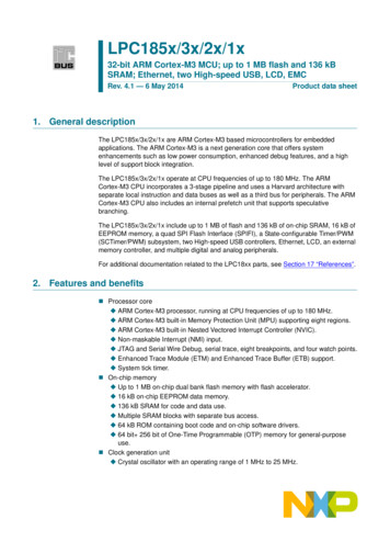
LPC185x/3x/2x/1xNXP Semiconductors32-bit ARM Cortex-M3 microcontroller5. Block diagramSWD/TRACE PORT/JTAGLPC185x/3x/2x/1x64 kB ROMHIGH-SPEED PHY32 kB LOCAL SRAM40 kB LOCAL SRAMTEST/DEBUGINTERFACEETMETHERNET(1)10/100MACIEEE 32 kB AHB SRAMUSB1(1)HOST/DEVICELCD(1)16 kB 16 kB AHB SRAMSD/MMCsystembusD-codebusI-codebus16 kB EEPROM512/256 kB FLASH Amasters512/256 kB FLASH BslavesAHB MULTILAYER MATRIXSPIFIslavesBRIDGE 0BRIDGE 1BRIDGE 2BRIDGE 3BRIDGEBRIDGEWWDTRI TIMERI2C1CGUALARM TIMERUSART0MOTORCONTROLPWM(1)USART210-bit DACCCU1BACKUP REGISTERSUART1I2C0USART3C CAN0CCU2POWER MODE CONTROLSSP0I2S0TIMER210-bit t ADC1TIMER1C CAN1SSP1EMCHS GPIOSCTEVENT ROUTEROTP MEMORYQEI(1)SCURTCRTC OSCGIMAGPIO PININTERRUPTS12 MHz IRCGPIO GROUP0INTERRUPTEVENT MONITORRTC POWER DOMAINGPIO GROUP1INTERRUPT connected to DMA002aah225(1) Not available on all parts. See Table 2.Fig 1.LPC185x/3x/2x/1x block diagramLPC185X 3X 2X 1XProduct data sheetAll information provided in this document is subject to legal disclaimers.Rev. 4.1 — 6 May 2014 NXP Semiconductors N.V. 2014. All rights reserved.6 of 148
LPC185x/3x/2x/1xNXP Semiconductors32-bit ARM Cortex-M3 microcontroller6. Pinning information6.1 PinningLPC185x/3xFET256ball A1index area2143658710912111413ball A1index LGKMHNJPRKT002aah356002aag541Transparent top viewTransparent top view104109LPC1857/53FBD208Fig 4.LPC183x/2x/1xFBD1441443715253120872002aag543Pin configuration LQFP208 packageFig 5.3615773Pin configuration TFBGA100 package108Fig 3.105Pin configuration LBGA256 package156Fig 2.9 10002aah357Pin configuration LQFP144 package6.2 Pin descriptionOn the LPC185x/3x/2x/1x, digital pins are grouped into 16 ports, named P0 to P9 and PAto PF, with up to 20 pins used per port. Each digital pin can support up to eight differentdigital functions, including General-Purpose I/O (GPIO), selectable through the SCUregisters.The pin name is not indicative of the GPIO port assigned to it.The parts contain two 10-bit ADCs (ADC0 and ADC1). The input channels of ADC0 andADC1 on dedicated pins and multiplexed pins are combined in such a way that all channel0 inputs (named ADC0 0 and ADC1 0) are tied together and connected to both, channelLPC185X 3X 2X 1XProduct data sheetAll information provided in this document is subject to legal disclaimers.Rev. 4.1 — 6 May 2014 NXP Semiconductors N.V. 2014. All rights reserved.7 of 148
LPC185x/3x/2x/1xNXP Semiconductors32-bit ARM Cortex-M3 microcontroller0 on ADC0 and channel 0 on ADC1, channel 1 inputs (named ADC0 1 and ADC1 1) aretied together and connected to channel 1 on ADC0 and ADC1, and so forth. There areeight ADC channels total for the two ADCs.Type47Description[1]32Reset stateLQFP208LBGA256Pin nameLQFP144Pin descriptionTFBGA100Table 3.Multiplexed digital pinsP0 0P0 1L3M2G2G13450[2][2]N;PUN;PUI/OGPIO0[0] — General purpose digital input/output pin.I/OSSP1 MISO — Master In Slave Out for SSP1.IENET RXD1 — Ethernet receive data 1 (RMII/MII interface).-R — Function reserved.-R — Function reserved.-R — Function reserved.I/OI2S0 TX WS — Transmit Word Select. It is driven by themaster and received by the slave. Corresponds to the signalWS in the I2S-bus specification.I/OI2S1 TX WS — Transmit Word Select. It is driven by themaster and received by the slave. Corresponds to the signalWS in the I2S-bus specification.I/OGPIO0[1] — General purpose digital input/output pin.I/OSSP1 MOSI — Master Out Slave in for SSP1.IENET COL — Ethernet Collision detect (MII interface).-R — Function reserved.-R — Function reserved.-R — Function reserved.ENET TX EN — Ethernet transmit enable (RMII/MIIinterface).P1 0P2LPC185X 3X 2X 1XProduct data sheetH13854[2]N;PUI/OI2S1 TX SDA — I2S1 transmit data. It is driven by thetransmitter and read by the receiver. Corresponds to the signalSD in the I2S-bus specification.I/OGPIO0[4] — General purpose digital input/output pin.ICTIN 3 — SCTimer/PWM input 3. Capture input 1 of timer 1.I/OEMC A5 — External memory address line 5.-R — Function reserved.-R — Function reserved.I/OSSP0 SSEL — Slave Select for SSP0.-R — Function reserved.I/OEMC D12 — External memory data line 12.All information provided in this document is subject to legal disclaimers.Rev. 4.1 — 6 May 2014 NXP Semiconductors N.V. 2014. All rights reserved.8 of 148
LPC185x/3x/2x/1xNXP Semiconductors32-bit ARM Cortex-M3 microcontrollerPin description continuedP1 2P1 3P1 4LQFP208K24258R3P5T3LPC185X 3X 2X 1XProduct data UTypeLQFP144R2Description[1]TFBGA100P1 1LBGA256Pin nameReset stateTable 3.I/OGPIO0[8] — General purpose digital input/output pin. Externalboot pin (see Table 5).OCTOUT 7 — SCTimer/PWM output 7. Match output 3 of timer1.I/OEMC A6 — External memory address line 6.-R — Function reserved.-R — Function reserved.I/OSSP0 MISO — Master In Slave Out for SSP0.-R — Function reserved.I/OEMC D13 — External memory data line 13.I/OGPIO0[9] — General purpose digital input/output pin. Externalboot pin (see Table 5).OCTOUT 6 — SCTimer/PWM output 6. Match output 2 of timer1.I/OEMC A7 — External memory address line 7.-R — Function reserved.-R — Function reserved.I/OSSP0 MOSI — Master Out Slave in for SSP0.-R — Function reserved.I/OEMC D14 — External memory data line 14.I/OGPIO0[10] — General purpose digital input/output pin.OCTOUT 8 — SCTimer/PWM output 8. Match output 0 of timer2.-R — Function reserved.OEMC OE — LOW active Output Enable signal.OUSB0 IND1 — USB0 port indicator LED control output 1.I/OSSP1 MISO — Master In Slave Out for SSP1.-R — Function reserved.OSD RST — SD/MMC reset signal for MMC4.4 card.I/OGPIO0[11] — General purpose digital input/output pin.OCTOUT 9 — SCTimer/PWM output 9. Match output 3 of timer3.-R — Function reserved.OEMC BLS0 — LOW active Byte Lane select signal 0.OUSB0 IND0 — USB0 port indicator LED control output 0.I/OSSP1 MOSI — Master Out Slave in for SSP1.I/OEMC D15 — External memory data line 15.OSD VOLT1 — SD/MMC bus voltage select output 1.All information provided in this document is subject to legal disclaimers.Rev. 4.1 — 6 May 2014 NXP Semiconductors N.V. 2014. All rights reserved.9 of 148
LPC185x/3x/2x/1xNXP Semiconductors32-bit ARM Cortex-M3 microcontrollerPin description continuedP1 6P1 7LQFP208J44865T4T5LPC185X 3X 2X 1XProduct data 5Description[1]TFBGA100P1 5LBGA256Pin nameReset stateTable 3.I/OGPIO1[8] — General purpose digital input/output pin.OCTOUT 10 — SCTimer/PWM output 10. Match output 3 oftimer 3.-R — Function reserved.OEMC CS0 — LOW active Chip Select 0 signal.IUSB0 PWR FAULT — Port power fault signal indicatingovercurrent condition; this signal monitors over-current on theUSB bus (external circuitry required to detect over-currentcondition).I/OSSP1 SSEL — Slave Select for SSP1.-R — Function reserved.OSD POW — SD/MMC card power monitor output.I/OGPIO1[9] — General purpose digital input/output pin.ICTIN 5 — SCTimer/PWM input 5. Capture input 2 of timer 2.-R — Function reserved.OEMC WE — LOW active Write Enable signal.-R — Function reserved.OEMC BLS0 — LOW active Byte Lane select signal 0.-R — Function reserved.I/OSD CMD — SD/MMC command signal.I/OGPIO1[0] — General purpose digital input/output pin.IU1 DSR — Data Set Ready input for UART1.OCTOUT 13 — SCTimer/PWM output 13. Match output 3 oftimer 3.I/OEMC D0 — External memory data line 0.OUSB0 PPWR — VBUS drive signal (towards external chargepump or power management unit); indicates that VBUS mustbe driven (active HIGH). Add a pull-down resistor to disable thepower switch at reset. This signal has opposite polaritycompared to the USB PPWR used on other NXP LPC parts.-R — Function reserved.-R — Function reserved.-R — Function reserved.All information provided in this document is subject to legal disclaimers.Rev. 4.1 — 6 May 2014 NXP Semiconductors N.V. 2014. All rights reserved.10 of 148
LPC185x/3x/2x/1xNXP Semiconductors32-bit ARM Cortex-M3 microcontrollerPin description continuedP1 9P1 10P1 11LQFP208H55171T7R8T9LPC185X 3X 2X 1XProduct data UTypeLQFP144R7Description[1]TFBGA100P1 8LBGA256Pin nameReset stateTable 3.I/OGPIO1[1] — General purpose digital input/output pin.OU1 DTR — Data Terminal Ready output for UART1.OCTOUT 12 — SCTimer/PWM output 12. Match output 3 oftimer 3.I/OEMC D1 — External memory data line 1.-R — Function reserved.-R — Function reserved.-R — Function reserved.OSD VOLT0 — SD/MMC bus voltage select output 0.I/OGPIO1[2] — General purpose digital input/output pin.OU1 RTS — Request to Send output for UART1.OCTOUT 11 — SCTimer/PWM output 11. Match output 3 oftimer 2.I/OEMC D2 — External memory data line 2.-R — Function reserved.-R — Function reserved.-R — Function reserved.I/OSD DAT0 — SD/MMC data bus line 0.I/OGPIO1[3] — General purpose digital input/output pin.IU1 RI — Ring Indicator input for UART1.OCTOUT 14 — SCTimer/PWM output 14. Match output 2 oftimer 3.I/OEMC D3 — External memory data line 3.-R — Function reserved.-R — Function reserved.-R — Function reserved.I/OSD DAT1 — SD/MMC data bus line 1.I/OGPIO1[4] — General purpose digital input/output pin.IU1 CTS — Clear to Send input for UART1.OCTOUT 15 — SCTimer/PWM output 15. Match output 3 oftimer 3.I/OEMC D4 — External memory data line 4.-R — Function reserved.-R — Function reserved.-R — Function reserved.I/OSD DAT2 — SD/MMC data bus line 2.All information provided in this document is subject to legal disclaimers.Rev. 4.1 — 6 May 2014 NXP Semiconductors N.V. 2014. All rights reserved.11 of 148
LPC185x/3x/2x/1xNXP Semiconductors32-bit ARM Cortex-M3 microcontrollerPin description continuedP1 13P1 14P1 15LQFP208K75678R10R11T12LPC185X 3X 2X 1XProduct data UTypeLQFP144R9Description[1]TFBGA100P1 12LBGA256Pin nameReset stateTable 3.I/OGPIO1[5] — General purpose digital input/output pin.IU1 DCD — Data Carrier Detect input for UART1.-R — Function reserved.I/OEMC D5 — External memory data line 5.IT0 CAP1 — Capture input 1 of timer 0.-R — Function reserved.-R — Function reserved.I/OSD DAT3 — SD/MMC data bus line 3.I/OGPIO1[6] — General purpose digital input/output pin.OU1 TXD — Transmitter output for UART1.-R — Function reserved.I/OEMC D6 — External memory data line 6.IT0 CAP0 — Capture input 0 of timer 0.-R — Function reserved.-R — Function reserved.ISD CD — SD/MMC card detect input.I/OGPIO1[7] — General purpose digital input/output pin.IU1 RXD — Receiver input for UART1.-R — Function reserved.I/OEMC D7 — External memory data line 7.OT0 MAT2 — Match output 2 of timer 0.-R — Function reserved.-R — Function reserved.-R — Function reserved.I/OGPIO0[2] — General purpose digital input/output pin.OU2 TXD — Transmitter output for USART2.-R — Function reserved.IENET RXD0 — Ethernet receive data 0 (RMII/MII interface).OT0 MAT1 — Match output 1 of timer 0.-R — Function reserved.I/OEMC D8 — External memory data line 8.-R — Function reserved.All information provided in this document is subject to legal disclaimers.Rev. 4.1 — 6 May 2014 NXP Semiconductors N.V. 2014. All rights reserved.12 of 148
LPC185x/3x/2x/1xNXP Semiconductors32-bit ARM Cortex-M3 microcontrollerPin description continuedP1 17P1 18P1 19LQFP208H96490M8N12M11LPC185X 3X 2X 1XProduct data ;PUTypeLQFP144M7Description[1]TFBGA100P1 16LBGA256Pin nameReset stateTable 3.I/OGPIO0[3] — General purpose digital input/output pin.IU2 RXD — Receiver input for USART2.-R — Function reserved.IENET CRS — Ethernet Carrier Sense (MII interface).OT0 MAT0 — Match output 0 of timer 0.-R — Function reserved.I/OEMC D9 — External memory data line 9.IENET RX DV — Ethernet Receive Data Valid (RMII/MIIinterface).I/OGPIO0[12] — General purpose digital input/output pin.I/OU2 UCLK — Serial clock input/output for USART2 insynchronous mode.-R — Function reserved.I/OENET MDIO — Ethernet MIIM data input and output.IT0 CAP3 — Capture input 3 of timer 0.OCAN1 TD — CAN1 transmitter output.-R — Function reserved.-R — Function reserved.I/OGPIO0[13] — General purpose digital input/output pin.I/OU2 DIR — RS-485/EIA-485 output enable/direction control forUSART2.-R — Function reserved.OENET TXD0 — Ethernet transmit data 0 (RMII/MII interface).OT0 MAT3 — Match output 3 of timer 0.ICAN1 RD — CAN1 receiver input.-R — Function reserved.I/OEMC D10 — External memory data line 10.IENET TX CLK (ENET REF CLK) — Ethernet TransmitClock (MII interface) or Ethernet Reference Clock (RMIIinterface).I/OSSP1 SCK — Serial clock for SSP1.-R — Function reserved.-R — Function reserved.OCLKOUT — Clock output pin.-R — Function reserved.OI2S0 RX MCLK — I2S receive master clock.I/OI2S1 TX SCK — Transmit Clock. It is driven by the masterand received by the slave. Corresponds to the signal SCK inthe I2S-bus specification.All information provided in this document is subject to legal disclaimers.Rev. 4.1 — 6 May 2014 NXP Semiconductors N.V. 2014. All rights reserved.13 of 148
LPC185x/3x/2x/1xNXP Semiconductors32-bit ARM Cortex-M3 microcontrollerPin description continuedP2 0P2 1LQFP208K1070100T16N15LPC185X 3X 2X 1XProduct data 44M10Description[1]TFBGA100P1 20LBGA256Pin nameReset stateTable 3.I/OGPIO0[15] — General purpose digital input/output pin.I/OSSP1 SSEL — Slave Select for SSP1.-R — Function reserved.OENET TXD1 — Ethernet transmit data 1 (RMII/MII interface).IT0 CAP2 — Capture input 2 of timer 0.-R — Function reserved.-R — Function reserved.I/OEMC D11 — External memory data line 11.-R — Function reserved.OU0 TXD — Transmitter output for USART0. See Table 4 forISP mode.I/OEMC A13 — External memory address line 13.OUSB0 PPWR — VBUS drive signal (towards external chargepump or power management unit); indicates that VBUS mustbe driven (active HIGH). Add a pull-down resistor to disable thepower switch at reset. This signal has opposite polaritycompared to the USB PPWR used on other NXP LPC parts.I/OGPIO5[0] — General purpose digital input/output pin.-R — Function reserved.IT3 CAP0 — Capture input 0 of timer 3.OENET MDC — Ethernet MIIM clock.-R — Function reserved.IU0 RXD — Receiver input for USART0. See Table 4 for ISPmode.I/OEMC A12 — External memory address line 12.IUSB0 PWR FAULT — Port power fault signal indicatingovercurrent condition; this signal monitors over-current on theUSB bus (external circuitry required to detect over-currentcondition).I/OGPIO5[1] — General purpose digital input/output pin.-R — Function reserved.IT3 CAP1 — Capture input 1 of timer 3.-R — Function reserved.All information provided in this document is subject to legal disclaimers.Rev. 4.1 — 6 May 2014 NXP Semiconductors N.V. 2014. All rights reserved.14 of 148
LPC185x/3x/2x/1xNXP Semiconductors32-bit ARM Cortex-M3 microcontrollerPin description continuedP2 3P2 4LQFP208F584121J12K11LPC185X 3X 2X 1XProduct data 4M15Description[1]TFBGA100P2 2LBGA256Pin nameReset stateTable 3.-R — Function reserved.I/OU0 UCLK — Serial clock input/output for USART0 insynchronous mode.I/OEMC A11 — External memory address line 11.OUSB0 IND1 — USB0 port indicator LED control output 1.I/OGPIO5[2] — General purpose digital input/output pin.ICTIN 6 — SCTimer/PWM input 6. Capture input 1 of timer 3.IT3 CAP2 — Capture input 2 of timer 3.OEMC CS1 — LOW active Chip Select 1 signal.-R — Function reserved.I/OI2C1 SDA — I2C1 data input/output (this pin does not use aspecialized I2C pad).OU3 TXD — Transmitter output for USART3. See Table 4 forISP mode.ICTIN 1 — SCTimer/PWM input 1. Capture input 1 of timer 0.Capture input 1 of timer 2.I/OGPIO5[3] — General purpose digital input/output pin.-R — Function reserved.OT3 MAT0 — Match output 0 of timer 3.OUSB0 PPWR — VBUS drive signal (towards external chargepump or power management unit); indicates that VBUS mustbe driven (active HIGH). Add a pull-down resistor to disable thepower switch at reset. This signal has opposite polaritycompared to the USB PPWR used on other NXP LPC parts.-R — Function reserved.I/OI2C1 SCL — I2C1 clock input/output (this pin does not use aspecialized I2C pad).IU3 RXD — Receiver input for USART3. See Table 4 for ISPmode.ICTIN 0 — SCTimer/PWM input 0. Capture input 0 of timer 0,1, 2, 3.I/OGPIO5[4] — General purpose digital input/output pin.-R — Function reserved.OT3 MAT1 — Match output 1 of timer 3.IUSB0 PWR FAULT — Port power fault signal indicatingovercurrent condition; this signal monitors over-current on theUSB bus (external circuitry required to detect over-currentcondition).All information provided in this document is subject to legal disclaimers.Rev. 4.1 — 6 May 2014 NXP Semiconductors N.V. 2014. All rights reserved.15 of 148
LPC185x/3x/2x/1xNXP Semiconductors32-bit ARM Cortex-M3 microcontrollerPin description iption[1]TFBGA100P2 5LBGA256Pin nameReset stateTable 3.-R — Function reserved.ICTIN 2 — SCTimer/PWM input 2. Capture input 2 of timer 0.IUS
the core supply and the RTC power domain. RTC power domain can be powered separately by a 3 V battery supply. Four reduced power modes: Sleep, Deep-sleep, Power-down, and Deep power-down. Processor wake-up from Sleep mode via wake-up interrupts from various peripherals. Wake-up from Deep-sleep, Power-down, and Deep power-down modes via