Transcription
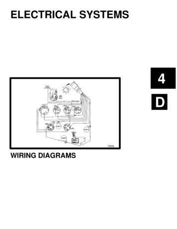
Color Diagrams75/90 FOURSTROKE EFI WIRINGDIAGRAM90-897725 MARCH 2005Page 8A-3
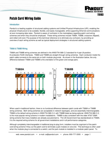
Color Diagrams75/90 FourStroke EFI Wiring Diagram1 - Electronic control module (ECM)2 - Engine water temperature sensor3 - Ignition coil for cylinder #1 and cylinder #44 - Ignition coil for cylinder #2 and cylinder #35 - Fuel injector #16 - Fuel injector #27 - Fuel injector #38 - Fuel injector #49 - Data test port10 - Main relay and fuel pump relay11 - Electric fuel pump12 - Splice saver13 - Throttle position sensor14 - Manifold air pressure/temperature sensor(MAP‑T)15 - Idle air control (IAC)16 - Oil pressure sensor17 - Shift switch18 - 30 ampere fuse ‑ electric starter circuit19 - 20 ampere fuse ‑ power trim circuitPage 8A-420 - 20 ampere fuse ‑ battery charging circuit21 - 20 ampere fuse ‑ main relay and fuel pump relay22 - Voltage regulator/rectifier23 - Stator ‑ 25 ampere24 - Trim indicator25 - Instruments26 - Crank position sensors27 - Malfunction indicator lamp (MIL) connection28 - Negative battery cable29 - Voltage regulator30 - Starter motor31 - Starter solenoid32 - Power trim relay33 - Cowl mounted trim switch34 - Remote control harness connector35 - Adaptor harness (model 2005)36 - Adaptor harness (model 2006)37 - Engine harness connector38 - Diode90-897725 MARCH 2005
1075/90 FourStroke EFI Wiring 219262524RED31WHT/BLKBLKRED/BLKGRN/YELGRNGRN/REDDK BLUBLU/WHTPNK/WHTWHTORG/WHTWHT/BLUBLU/YELREDREDLT BLULT GRNLT BLULT GRNLT BLULT GRNBLKREDBLKBLKPNK/BLKGRNBRNGRN/BLKREDDK BLULT BLULT GRNLT BLULT GRNREDLT GRNGRNWHT/BLKPNK/WHT3534BLKWHT/BLKORGPNK/GRNLT BLULT GRNGRN/YELGRNGRNGRN/REDPNKPNK/WHTWHTYELLT BLUBLKLT GRNBLU/YEL233738GRNBLKPNKWHTYEL36LT BLULT GRNFEDPNCMGABHJKL13228LT BLU/WHTLT GRN/WHTDK /REDREDBLKBLKDK K34 9303132333429REDBLK91REDBLUYELLT PNKLT BLUBLK/YELLT GRNWHT/BLKLT HTWHTBLKWHTWHTWHTREDBLKBLU/YELLT BLU10 1123456789101112131415161718LT GRN/WHTREDLT LKBLK/YELGRNBLKBLKBLKBLKBLKBLKBLKBLKLT GRNLT GRNLT GRNLT GRNLT BLULT BLULT BLULT BLUGRNGRNBLKDK BLUREDRED/YELRED/YELYELGRNBLKDK BLUDK /REDBLKBLK/YELPNKBLKORG28
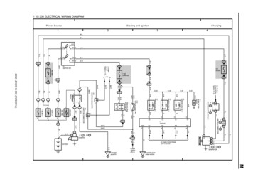
Color Diagrams75/90 FOURSTROKE EFI TYPICALGAUGES WITH TACH SIGNALCONVERTER90-897725 MARCH 2005Page 8A-5
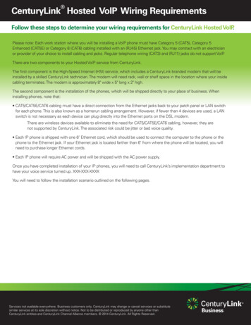
Color Diagrams75/90 FourStroke EFI Typical Gauges with Tach Signal Converter123456-Panel Control 4000Neutral lock buttonTrim switchThrottle only buttonLanyard stop switchLanyard stop switch leads must be soldered and covered with shrink tube for a water proof connection.If alternate method of connection is made (use of electrical butt connector) verify connection is secureand seal for moisture proof connection.7 - Trim harness connection8 - Connect wires together with screw and hex nut (2 places). Apply Liquid Neoprene to connections andslide heat shrink tubing over each connection.9 - Ignition key switch10 - 5‑pin tachometer harness connector11 - Warning horn12 - Speedometer13 - Temperature gauge14 - Trim Position gauge15 - Tachometer16 - Light switch connection17 - Tachometer signal converter (required for correct tachometer operation for 2001 model year)18 - To warning light ( if equipped)19 - To trim sender (if equipped)20 - To engine trim harness connections21 - To temperature sensor (if equipped)22 - Remote control harness connectionPage 8A-690-897725 MARCH 2005
75/90 FourStroke EFI Typical GaugesWith Tach Signal GN.5P6P2P4CSEND.678179222120C19D11BEA181013232
Color Diagrams75/90 FOURSTROKE EFI FUEL FLOWDIAGRAM90-897725 MARCH 2005Page 8A-7
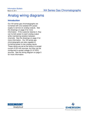
Color Diagrams75/90 FourStroke EFI Fuel Flow Diagram1 - Boat fuel tank2 - Water separating fuel filter assembly3 - Mechanical fuel pump4 - Fuel filter (in‑line)5 - Float valve assembly6 - High pressure fuel pump filter7 - Vapor Separator Tank (VST) drain fitting8 - Vapor Separator Tank (VST) drain screw9 - High pressure fuel pump10 - Vapor Separator Tank (VST) fuel vapor fitting11 - High pressure fuel out to fuel rail12 - Fuel pressure regulator13 - Fuel cooler14 - Fuel return to VST from fuel cooler fitting15 - Fuel rail16 - Fuel injector17 - Fuel pressure regulator internal view18 - Fuel pressure regulator vent to intake manifold19 - High pressure fuel inlet to fuel pressure regulator20 - High pressure fuel to fuel cooler21 - Vent to atmosphere22 - Vapor canister filter23 - Vapor canister24 - To intake manifoldFuel Color CodePage 8A-8YellowFuel vaporOrangeFuel is under low pressureRedFuel is under high pressure90-897725 MARCH 2005
75/90 FourStroke EFI Fuel 413229
Color Diagrams75/90 FOURSTROKE EFI OIL FLOWDIAGRAM90-897725 MARCH 2005Page 8A-9
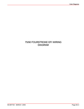
Color Diagrams75/90 FourStroke EFI Oil Flow Diagram1 - Sump2 - Oil pick‑up3 - Adapter plate4 - Oil pump and pressure regulator5 - Cylinder block with oil passages6 - Oil filter7 - Crankshaft with oil passages8 - Cylinder head with oil passages9 - Camshafts10 - Oil drains from head to block11 - Oil in block drains through adapter plate back to the sump.Page 8A-1090-897725 MARCH 2005
75/90 FourStroke EFI Oil Flow7613524115810913231
Color Diagrams75/90 FOURSTROKE EFI WATERFLOW DIAGRAM90-897725 MARCH 2005Page 8A-11
Color Diagrams75/90 FourStroke EFI Water Flow Diagram1 - Water inlet2 - Water pump3 - Driveshaft housing4 - Water tube5 - Oil sump6 - Adapter plate7 - Cylinder block8 - Cylinder head9 - Thermostat 60 C (140 F)10 - Water jacket cover11 - Water pressure relief valve12 - Fuel cooler13 - Tee fitting14 - Tell‑tale15 - Driveshaft bushingPage 8A-1290-897725 MARCH 2005
75/90 FourStroke EFI Water Flow11121013171562435149813230
Color Diagrams Page 8A-4 90-897725 MARCH 2005 75/90 FourStroke EFI Wiring Diagram 1 - Electronic control module (ECM) 2 - Engine water temperature sensor 3 - Ignition coil for cylinder #1 and cylinder #4 4 - Ignition coil for cylinder #2 and cylinder #3 5 - Fuel injector #1 6 - Fuel injector #2 7 - Fuel injector #3 8 - Fuel injector #4 9 - Data .