Transcription
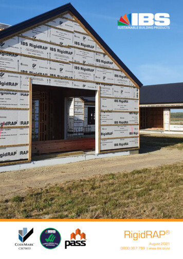
IBS RigidRAP RIGID AIR BARRIER &STRUCTURAL BRACING PANELDESIGN & INSTALLATION GUIDEOCTOBER 2020 V2.0Please allow 2mm gap around all 4 sides of the boardIBS RigidRAP Installation Guide V2.00800 367 759www.ibs.co.nzinfo@ibs.co.nz
Contents1.0 Purpose of Document1.1 General . 31.2 Supporting Information . 32.0 Product Information2.1 Use of IBS RigidRAP . 32.2 OSB3 Explained . 32.3 IBS RigidRAP Explained . 32.4 Wall Underlay . 32.5 CodeMark Explained . 32.6 IBS RigidRAP Advantages . 42.7 Restricted Building Work . 42.8 Install Service Penetration . 42.9 Install Window Opening . 42.10 Designer/Installer Skill Level . 42.11 Health and Safety . 42.12 Handling and Storage . 52.13 Sawing, Drlling, Shaping . 52.14 IBS RigidRAP Measurements . 52.15 IBS RigidRAP Comparison . 54.0 Rigid Air Barrier4.1 General . 144.2 Non-Structural Rigid Air Barrier . 145.0 Internal Lining . 156.0 Available Details . 157.0 Finishing . 158.0 Quality Assurance . 169.0 Additional Resources . 1610.0 Technical Properties . 1610.1 OSB Technical Properties . 1610.2 RigidRAP Technical Properties . 1711.0 Limitations . 1712.0 FAQ. 183.0 Bracing Element3.1 Scope of Use . 63.2 Limitations . 63.3 Wall Bracing System . 73.3.1 Bracing Capacity . 73.3.2 System #1 . 83.3.3 System #2 . 83.3.4 System #3 . 93.3.5 System #4 . 93.3.6 System #5 . 103.3.7 System #6 . 103.3.8 System #7 . 113.3.9 System #8 .113.3.10 System #9 .113.3.11 Lintel Tie Down Details. 123.3.12 Top Plate Connections. 123.3.13 Fixings. 123.3.13.1 Bottom Plate Fixings . 123.3.13.2 Bottom Plate Details . 133.3.14 Mechanical Connections. 143.4 Joint Sealing and Window Tape . 14OCTOBER 2020 - Version 2.0
1.0 Purpose of Document1.1 GENERAL1.2 SUPPORTING INFORMATIONThis document is intended for designers and installers toensure that IBS RigidRAP (rigid air panel) is specified andinstalled correctly.This document must be read in conjunction with the: IBS Product Specification for IBS RigidRAP IBS Maintenance and Warranty for IBS RigidRAP All other information is available at www.ibs.co.nz.2.0 Product Information2.1 USE OF IBS RigidRAP IBS supply IBS RigidRAP for use: As an internal or external wall bracing element whenused in conjunction with a specific fixing system. In exterior wall construction as an alternative to lightor heavyweight wall wrap or where a rigid air barrier isrequired. As an internal wall substrate where high impact use isenvisaged. IBS RigidRAP can be used as a temporary weather claddingfor up to 90 days exposure.IBS RigidRAP meets all the requirements of Table 23(clause E2 - external moisture) from the compliancedocument for the NZ Building Code.2.2 OSB3 EXPLAINED2.4 WALL UNDERLAYOSB3 (oriented strand board 3) is a moisture resistant,structural wood panel. Engineered in Germany fromenvironmentally sustainable sourced softwood, it consistsof three layers of wood strands bonded together with heatcured adhesives. Each layer is orientated at right angles tothe adjacent layer creating a strong, dimensionally stablepanel that resists delamination and warping. The absenceof natural imperfections such as knots provides certainty ofperformance.Wall underlay is a synthetic wall underlay. The productconsists of a micro-porous water resistant polypropylenefilm laminated between two layers of spunbondedpolypropylene.2.3 IBS RigidRAP EXPLAINEDIBS RigidRAP has been manufactured specifically forNZ, for use as a bracing element and/or rigid air barrier.It comes laminated with a BRANZ appraised watertight wallunderlay.As an OSB3 panel, manufactured in accordance withEN13986:2004, it is suitable for use in humid conditionswhere the panel in-service moisture content does notexceed 20%.IBS RigidRAP is 8mm thick and supplied in the followingpanel sizes: 2440 mm x 1196 mm x 8 mm 2745 mm x 1196 mm x 8 mm 3050 mm x 1196 mm x 8 mm2.5 IBS RigidRAP CODEMARK EXPLAINEDIBS is the certificate holder of CodeMark for IBS RigidRAP .CodeMark is third party certified, allowed forunder the Building Act 2004. This means that under law, aBuilding Consent Authority must accept the specification ofIBS RigidRAP (the panel and the installation details)as complying with the NZ Building Code, providing that allconditions of the certificate have been met.Achieving CodeMark also focuses on the quality of IBSRigidRAP panels and the quality and competence of thesupport provided by IBS. This means that designers andinstallers can use IBS RigidRAP with confidence that,providing all instructions are followed, IBS RigidRAP willresult in building work complying with the NZ BuildingCode.Compliance with the NZ Building Code (NZBC) isestablished through Product Certification (CodeMark).IBS RigidRAP Installation Guide V1.1Please allow 2mm gap around all 4 sides of the board3
2.6 IBS RigidRAP ADVANTAGESIBS RigidRAP is a practical alternative to traditional flexiblebuilding wraps. The installation of IBS RigidRAP allowsthe builder to enclose the exterior of the building quicklyproviding the following advantages: Reduces building time Provides rapid moisture protection of the building Allows for interior construction to continue Provides a greater level of site security Reduces structural timber movement2.7 RESTRICTED BUILDING WORKIn some applications Restricted Building Work (RBW)provisions will apply. It is the responsibility of the designerand installer to ensure that they have met their obligationsunder these provisions.Min lap150 mmin eachdirectionTypical window openingIBS RigidRAP 2.8 INSTALL SERVICE PENETRATIONFlexible flashing tape(ref section 3.4)Refer to IBS RigidRAP approved selection of flexibleflashing tapes - see 3.4.Flashing of pipe and service penetrations shall be carriedout in accordance with the following: Pipe penetrations through IBS RigidRAP must have aminimum of 5 slope to the outside. Flexible flashing tape must be installed like a bandagewith a minimum of 25 mm cover around the pipe and100 mm minimum surface adhesion to IBS RigidRAP panel surrounding the penetration.2.9 INSTALL WINDOW OPENINGRefer to IBS RigidRAP approved selection of flexibleflashing tapes - see 3.4.Flashing window openings shall be carried out inaccordance with WANZ Guide to E2/ASI (6), substitutingbuilding wraps for IBS RigidRAP . Cut the flashing tape for the sill at least 200 mm widerthan the opening. Fit the tape with the inner edge of the tape flush withthe inside line of the framing and extend 100 mm upand down each jamb edge. Ensure the tape is well adhered to the surfaces andfitted tightly to each corner. Fully tape all window opening edges.NOTE: All window tapes should be used in accordance withthe manufacturer’s installation guide.42.10 DESIGNER/INSTALLER SKILL LEVELWhere IBS RigidRAP is specified and/or installedthe designer/installer should have the appropriate skills,knowledge of the product and access to all IBS RigidRAP technical information (reference www.ibs.co.nz).2.11 HEALTH AND SAFETYWhen installing IBS RigidRAP take all steps to ensureyour safety and the safety of others. Ensure that when cutting or drilling IBS RigidRAP that there is adequate ventilation or mechanical dustextraction. Ensure IBS RigidRAP is well supported whencutting or drilling the panel. Appropriate close fit clothing should be worn at all times Wear eye, ear and footwear protection when workingwith IBS RigidRAP .Site considerations Selection of the right equipment for working from a height Safe working with ladders and stepladders Maintain a clear unobstructed work areaFor further information refer to: The Absolutely Essential Health and Safety Toolkit Worksafe New Zealand Quick GuidePlease allow 2mm gap around all 4 sides of the boardIBS RigidRAP Installation Guide V2.0
2.12 HANDLING AND STORAGE2.13 SAWING, DRILLING, SHAPINGCorrect storage and handling in transport is essential forthe protection of IBS RigidRAP . The following simpleprinciples should be taken into account:IBS RigidRAP panels may be sawn and shaped in thesame way as solid wood, although carbide tipped cuttersare recommended. Strapping and shrink wrap should be removedimmediately upon arrival at the installer’s storage area oron site. IBS RigidRAP should be laid flat on timber bearers. Thespacing’s between the timber should be no more than800 mm. If several pallets are stacked on top of each other ensurethe storage bearers are in true alignment. When stored outside ensure there is sufficient clearancebetween the ground and IBS RigidRAP to prevent moisturetransfer and allow air circulation. Cover with a waterprooftarpaulin. IBS RigidRAP must not be exposed to the weather formore than 90 days. When manually handling IBS RigidRAP ensure the panelsare lifted in the central third. IBS RigidRAP should be allowed to climatise to the siteconditions for 48 hours prior to installation.If panels are to be installed in a visible location, ensureclean-cut edges with sharp tools, using a backing block tominimize break out. The feed rate should be slower than forsolid wood.When IBS RigidRAP has been cut, you must seal the cutedges with tape or a waterproof product to prevent theingress of moisture asap.2.14 IBS RigidRAP SHEET MEASUREMENTSLength (mm)Width (mm)Thickness (mm)Weight (kg)24401196816.927451196818.6305011968202.15 IBS RigidRAP COMPARISONBracing Units (BU/m) Based on 2400 x 1200 Sheet SizeProductWindEarthquakePlywood 7 mm123139Cement Board 6 mm125102OSB3 8 mm131107IBS RigidRAP Installation Guide V2.0Please allow 2mm gap around all 4 sides of the board5
3.0 Bracing Element3.1 SCOPE OF USEIBS RigidRAP may be used as a bracing element withinthe following scope:In wind zones: Up to and including extra high. Up to 2.5 kPa ULS where the building is specificallyengineered.Building scope New buildings: with timber wall framing complying withNZ Building Code . In conjunction with the GIB HandiBrac method or aStrap Bracing system. In conjunction with LVL System - staples, Mitek CPC 80and SPAX screws. In conjunction with LVL System - staples, SimpsonStrong-Tie DTT2Z and type 17 screws. In conjunction with concrete and timber subfloorapplications that comply with the NZ Building Code. With all cladding types that comply with NZBC. In conjunction with a drained and ventilated nominal20mm cavity system. With aluminium joinery complying with the NZBC IBS RigidRAP -XT must be used in conjunction with steelframing, for both Structural bracing and as a Rigid AirBarrier.IBS RigidRAP may be used as a bracing element inexisting buildings, however in these cases IBS makes noclaim as to the bracing value that will be achieved. If IBSRigidRAP is to be installed as a bracing element in existingtimber framed buildings the following scope applies: Existing timber framed buildings where the designer and/or installer have assured themselves that the existingbuilding is suitable for the intended building work. Existing concrete and timber sub-floor structures wherethe designer and/or installer have assured themselves thatthe existing building is suitable for the intended buildingwork.Serviceability of the joints may be affected if - at the timethe timber framing is installed - its moisture content isgreater than 18%. For wall heights greater than 3050 mm horizontal walljoints are permitted, provided the panel joint is over solidblocking of the same gauge as the studs. All joints, other than mid floor level, (vertical andhorizontal) must be sealed with an IBS approved selfadhesive “flashing tape” as specified in section 3.4. IBSrecommend 150 mm flashing tape or a proprietary Zflashing for horizontal joins. A hole 100 x 100 mm maximum within an envelope of 100mm from top and vertical edges and 200 mm from thebottom of the IBS RigidRAP panel will not affect thebracing capacity. Multiple holes of this size are permittedprovided the centre lines of the holes are not closer than600 mm. Steel fixings and fastenings must be in accordance withtable 4.1, NZS 3604: 2011. IBS RigidRAP must be allowed to acclimatise for atleast 48 hours prior to installation. Do not install IBS RigidRAP if the building paper hasdelaminated from the OSB sheet.When specifying IBS RigidRAP as a bracing element, thedesigner must take into account site specific conditionsand the building with respect to, but not limited to, thefollowing: Environmental (exposure) zone Wind zone Wall bracing table for wind and EQ demand Structural design loads Structural framing requirements Preparation of substrate External envelope Other materials likely to affect the performance ofIBS RigidRAP 3.2 LIMITATIONS Allow a minimum of 4 mm between panel joints toaccommodate dimension movement. Maximum spacings of wall studs must not exceed 600 mmcentres. Curved walls, minimum radius 2.5 m are allowable, theIBS RigidRAP panels must be fixed horizontally ontoframing studs with spacing and stud centres dependenton the radius. A proprietary ‘Z’ flashing must be installed at mid floorlevel where IBS RigidRAP is installed on multi levels.6Please allow 2mm gap around all 4 sides of the boardIBS RigidRAP Installation Guide V2.0
3.3 IBS RigidRAP WALL BRACING SYSTEM3.3.1 BRACING CAPACITYThe following table provides the bracing value for the different systems:Table 1Concrete SlabTimber FloorSystemWindEQWindEQSYSTEM 1:OSB - 300 mm x 2400 mm wall with GIB HandiBrac Fixing 30 mm x 2.5 mm Galv clouts49 BU/m58BU/m49 BU/m58 BU/mSYSTEM 2:OSB - 400 mm x 2400 mm wall with GIB HandiBrac Fixing 30 mm x 2.5 mm Galv clouts.70 BU/m79 BU/m70 BU/m79 BU/mSYSTEM 3:OSB - 600 mm x 2400 mm wall with GIB HandiBrac Fixing 30 mm x 2.5 mm Galv clouts76 BU/m81 BU/m76 BU/m81 BU/mSYSTEM 4:OSB - 1200 mm x 2400 mm wall with GIB HandiBrac Fixing 30 mm x 2.5 mm Galv clouts131 BU/m107 BU/m131 BU/m107 BU/mSYSTEM 5:OSB - 2400 mm x 2400 mm wall with GIB HandiBrac Fixing 30 mm x 2.5 mm Galv clouts108 BU/m89 BU/m108 BU/m89 BU/mSYSTEM 6:OSB - 1200 mm x 2400 mm wall without GIB HandiBrac Fixing 30 mm x 2.5 mm Galv clouts93 BU/m78 BU/m93 BU/m78BU/mSYSTEM 7:OSB - 400 mm x 2400 mm wall with GIB HandiBrac GIB standard 10 mm board on the insideFixing 30 mm x 2.5 mm Galv clouts94 BU/m104 BU/m94 BU/m104 BU/mSYSTEM 8:OSB - 600 mm x 2400 mm wall with GIB HandiBrac GIB standard 10 mm board on the insideFixing 30 mm x 2.5 mm Galv clouts130 BU/m130 BU/m120 BU/m120 BU/mSYSTEM 9:OSB - 1200 mm x 2400 mm wall with GIB HandiBrac GIB standard 10 mm board on the insideFixing 30 mm x 2.5 mm Galv clouts150 BU/m150 BU/m130 BU/m130 BU/mNOTE: For all bracing systems no product substitution is allowed.Installation must be in accordance with these instructions.If these requirements are not met, IBS provides noassurance that the bracing capacity (claimed in this designand installation guide) will be achieved. The allowable racking resistances for the IBS RigidRAP systems are applicable to frames lined with IBS RigidRAP on one side only. Panels must always be installed vertically if used asbracing sheet. Sheets can be installed horizontally if notused as a bracing element. All IBS RigidRAP systems have been tested with no nogs ordwangs Stud sizes and centres will vary depending on height loadand loads ref: NZS3604:2011.IBS RigidRAP Installation Guide V2.0The systems may be used on walls of lengths different tothose in TABLE 1 but is limited to: Wall lengths no greater than twice the tested systemlength. For walls greater than the tested system length multiplythe length of the wall on a pro-rata basis, up to double thelength of the system. A wall height less than 1.5 meters should be referred to aspecific engineer design. A wall height less than 2.4 meters should be rated as ifthey are 2.4 meters high. Panels higher than IBS RigidRAP 2440 mm must be fixedtop plate to bottom plate. When walls are higher than 2440mm, IBS RigidRAP 2745 or 3050 mm sheets can be used. A part sheet can be used but must be nogged and nailedas per specification.Please allow 2mm gap around all 4 sides of the board7
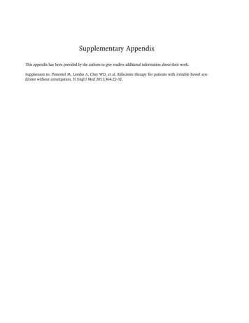
300 mm3.3.2 SYSTEM #1SYSTEM 1 IBS RigidRAP 300 x 2400 MM WALL USING GIBHANDIBRAC - FIG 1Wall construction: 90 x 45 MSG8 studs. 8 mm IBS RigidRAP panel one side. 30 x 2.5 mm galv clouts at 150 mm centres around theperimeter. GIB HandiBrac hold down brackets fixed to each end-toend studs and to bottom plate with concrete hold downs asper manufacturer’s specifications. Tested on a concrete floor with M12 hold-down bolts.FIG 1Corner nailin 25 mmfrom eachedge2400 mm150 mmGIB HandiBrac installed in theinternal cornerGIB HandiBrac installed in theinternal corner3.3.3 SYSTEM #212 mm infrom edgeSYSTEM 2 IBS RigidRAP 400 x 2400 MM WALL USING GIBHANDIBRAC - FIG 2Wall construction: 90 x 45 MSG8 studs. 8 mm IBS RigidRAP panel one side. 30 x 2.5 mm galv clouts at 150 mm centres around theperimeter. GIB HandiBrac hold down brackets fixed to each end-toend studs and to bottom plate with concrete hold downs asper manufacturer’s specifications. Tested on a concrete floor with M12 hold down bolts.400 mmFIG 2Corner nailin 25 mmfrom eachedge2400 mm150 mmGIB HandiBrac installed in theinternal corner812 mm infrom edgePlease allow 2mm gap around all 4 sides of the boardGIB HandiBrac installed in theinternal cornerIBS RigidRAP Installation Guide V2.0
12 mm infrom edge3.3.4 SYSTEM #3SYSTEM 3 IBS RigidRAP 600 x 2400 MM WALL USINGGIB HANDIBRAC - FIG 3Wall construction: 90 x 45 MSG8 studs. 8 mm IBS RigidRAP panel one side. 30 x 2.5 mm galv clouts at 150 mm centres around theperimeter. GIB HandiBrac hold down brackets fixed to each end-toend studs and to bottom plate with concrete hold downs asper manufacturer’s specifications. Tested on a concrete floor with M12 hold down bolts.600 mmFIG 3Corner nailin 25 mmfrom eachedge2400 mm150 mmGIB HandiBrac installed in theinternal cornerGIB HandiBrac installed in theinternal corner12 mm infrom edge1200 mm3.3.5 SYSTEM #4SYSTEM 4 IBS RigidRAP 1200 x 2400 MM WALL USINGGIB HANDIBRAC - FIG 4Wall construction: 90 x 45 MSG8 studs (600 centres) plates. 8 mm IBS RigidRAP panel one side. 30 x 2.5 galv clouts at 150 mm centres around theperimeter. GIB HandiBrac hold down brackets attached to eachend studs and to the bottom plate with concrete holddowns as per manufacturer’s specifications. Tested on a concrete floor with M12 hold down bolts.FIG 4Corner nailin 25 mmfrom eachedge2400 mm300 mm150 mmGIB HandiBrac installed in theinternal cornerGIB HandiBrac installed in theinternal corner600 mmIBS RigidRAP Installation Guide V2.0Please allow 2mm gap around all 4 sides of the board9
12 mm infrom edge3.3.6 SYSTEM #5SYSTEM 5 IBS RigidRAP 2400 x 2400 MM WALL USINGGIB HANDIBRAC - FIG 5Wall construction: 90 x 45 MSG8 studs (600 mm centres) plates. 8 mm IBS RigidRAP panel one side. 30 x 2.5 mm galv clouts at 150 mm centres around theperimeter. GIB HandiBrac hold down brackets fixed to each end-toend studs and to bottom plate with concrete hold downs asper manufacturer’s specifications. Tested on a concrete floor with M12 hold-down bolts.FIG52400 mm300 mmCorner nailin 25 mmfrom eachedge2400 mm150 mm1200 mmGIB HandiBrac installed in theinternal corner1200 mmGIB HandiBrac installed in theinternal corner12 mm infrom edge3.3.7 SYSTEM #61200 mmSYSTEM 6 IBS RigidRAP 1200 x 2400 MM WALL - FIG 6Wall construction: 90 x 45 MSG8 studs (600 mm centres) plates. 8 mm IBS RigidRAP panel one side. 30 x 2.5 mm galv clouts at 150 mm centres around theperimeter. No hold down bracketsFIG 62400 mmCorner nailin 25 mmfrom eachedge300 mm150 mm600 mm10Please allow 2mm gap around all 4 sides of the boardIBS RigidRAP Installation Guide V2.0
400 mmFIG 73.3.8 SYSTEM #7SYSTEM 7 IBS RigidRAP 400 x 2400 MM WALL USINGGIB HANDIBRAC AND GIB BOARD - FIG 7Wall construction: 90 x 45 MSG8 studs. 8 mm IBS RigidRAP panel one side. 30 x 2.5 mm galv clouts at 150 mm centres around theperimeter. GIB HandiBrac hold down brackets fixed to each end-toend studs and to bottom plate with concrete hold downs asper manufacturer’s specifications. GIB standard 10 mm board on the inside. Tested on a concrete floor with M12 hold down bolts.Corner nailin 25 mmfrom eachedge2400 mm150 mmGIB HandiBrac installed in theinternal cornerGIB HandiBrac installed in theinternal corner600 mmFIG 83.3.9 SYSTEM #8SYSTEM 8 IBS RigidRAP 600 x 2400 MM WALL USINGGIB HANDIBRAC AND GIB BOARD - FIG 8Wall construction: 90 x 45 MSG8 studs. 8 mm IBS RigidRAP panel one side. 30 x 2.5 mm galv clouts at 150 mm centres around theperimeter. GIB HandiBrac hold down brackets fixed to each end-toend studs and to bottom plate with concrete hold downs asper manufacturer’s specifications. GIB standard 10 mm board on the inside. Tested on a concrete floor with M12 hold down bolts.2400 mm150 mmGIB HandiBrac installed in theinternal cornerGIB HandiBrac installed in theinternal cornerFIG 9SYSTEM 9 IBS RigidRAP 1200 x 2400 MM WALL USINGGIB HANDIBRAC AND GIB BOARD - FIG 9Wall construction: 90 x 45 MSG8 studs (600 mm centres) plates. 8 mm IBS RigidRAP panel one side. 30 x 2.5 mm galv clouts at 150 mm centres around theperimeter. GIB HandiBrac hold down brackets fixed to each end-toend studs and to bottom plate with concrete hold downs asper manufacturer’s specifications. GIB standard 10 mm board on the inside. Tested on a concrete floor with M12 hold down bolts.12 mm infrom edgeCorner nailin 25 mmfrom eachedge1200 mm3.3.10 SYSTEM #912 mm infrom edgeCorner nailin 25 mmfrom eachedge12 mm infrom edge2400 mm300 mm150 mmGIB HandiBrac installed in theinternal cornerGIB HandiBrac installed in theinternal corner600 mmIBS RigidRAP Installation Guide V2.0Please allow 2mm gap around all 4 sides of the board11
3.3.11 LINTEL TIE DOWN DETAILSAllowable upliftresistance (kN/rafter)Fastener spacing (mm)top and bottom plates7.5758.540Where the uplift does not exceed 7.5kN, the following strapfixing detail may be used as an alternate to 7.5kN strapfixing detailed in NZ3604, fig 8.12.min. 1200 mmTop plate75 mmLintel, min 140 deep6/50 x 2.8Ø nails10/50 x 2.8Ø nails,prebored holes 2.5Ø.See pattern belowAdditional 50 x 2.8Øbetween existing nails @150 c.cIBS RigidRAP TensionBase fixing as per fig. 8.12NZS3604 (2011)1515152875 mm10 715 minBottom plate to floor or sub floor connection as per NZS 3604:201125 c/c min25 c/c minTrim studUnder stud3.3.13 FIXINGS3.3.13.1 GENERALFixingExposure Zone15 minType 304 S/ Steel, Gauge8 x 25 Surefix ScrewsAll exposure zonesEdge of IBSRigidRAP 45 x 2.5 S/Steel AnnularGrooved NailsAll exposure zones30 x 2.5 Galv Clouts,round head or D-HeadExposure zone B & C only3.3.12 TOP PLATE TO RAFTER OR TRUSSCONNECTIONSRAP sheathed wall frames transfer these uplift loads to thebottom plates; the IBS RigidRAP acting in tension as acontinuous cycle rod. Refer to NZS3604:2011 Table8.18 for uplift connections between top plate and roofframing. Rafter/truss spacing is determined by the loadeddimensions.3.3.13.2 BOTTOM PLATE FIXINGBottom plate fixingExposure zoneGIB HandiBrac Use supplied hold-down boltsSteel fixing as per table 4:1NZS3604:2011Top plate / stud mechanical fixingsUplift top plate/stud mechanical connections in accordancewith NZS3604: 2011 up to 7.5kN can be omitted where IBSRigidRAP and fixings are installed (top and bottom plates)at a maximum spacing of 75 mm.12Please allow 2mm gap around all 4 sides of the boardIBS RigidRAP Installation Guide V2.0
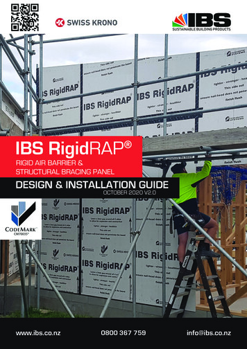
GIB HANDIBRAC INSTALLATION - CONCRETEFLOOR3.3.13.3 BOTTOM PLATE FIXING DETAILSBASE DETAILExternalwallsInternalwallsPosition IBS RigidRAP as close as practicable to theinternal edge of the bottomplate.Position IBS RigidRAP atthe stud/plate junctionInterior lining15 mm40 mmIBS RigidRAP Damp proof course6 mm gap or provide waterproof membrane betweenconcrete slab or blockmasonryBottom plate detail to concrete or timber floor (with 25 mm x 1 mm strap)GIB HANDIBRAC INSTALLATION - TIMBER FLOOR4 or 6 nails perLEG as specified100 mmmaximumExternalwallsInternalwalls100 mmmaximumCyclone Strapfixed to side eg: QH5S6Position IBS RigidRAP in the centre of the perimeterjoist or bearer.IBS RigidRAP Installation Guide V2.0Position IBS RigidRAP inthe centre of the floor joist orfull depth solid block.Please allow 2mm gap around all 4 sides of the board13
3.3.14 MECHANICAL CONNECTIONS(UPLIFT & HOLD DOWN)ConnectionsCyclone ties (304-2B Stainless Steel)Nails SS 30 mm x 3.15 mm indiameterExposure zoneThe following tapes may be used to seal panels:Approved Joint and Window Tape (minimum face cover 50 mm)All exposure zones1 x 25 - Sheet Brace Strap (304-2BStainless Steel)Nails SS 6/30 x 3.15 diameter nailsper strap end for 6kN capacity, 2straps for 12kNAll exposure zonesGIB HandiBrac ets/gibhandibrac/All exposure zonesCyclone Ties(G300 Z275 Galvanised Steel)Nails 30 mm x 3.15 mm in diameterExposure zones B & C only1 x 25-Sheet Brace strap (G300 Z275Galvanised Steel)Nails 6/ 30 x 3.15 diameter nails perstrap end for 6kN capacity, 2 strapsfor 12kNExposure zones B & C onlyMitek angle bracket CPC80 - 1.55,G300, Z275, 16 x 30 mm x 3.15 mmdia. 8/Type 17, 14g x 35 hex headExposure zones B & C onlySimpson Strong-Tie DTT2Z 1.74 mm, G-185, 8 x 6 mm dia x 40screws, M12 galv. threaded rod,ChemSet3.4 JOINT SEALING AND WINDOW TAPE FORIBS RigidRAP Hydro Tape (masons75 mm)www.mpb.co.nz/product/hydrowindowtapeMasons 40 Belowwww.mpb.co.nz/product/40below-2SUPER-STICK (MarshallInnovations)www.mwnz.com/super wflashing-tapes3M All Weather FlashingTape 8067www.3mnz.co.nzDristud Cool w-flashing-tapesTESCON EXTORIA IBS-OS(Pro essEUROBAND 560www.frameprotection.co.nzExposure zones B & C onlyThe tape is to be installed in accordance with the specificsupplier instructions.All joints and penetrations must be sealed including: Vertical and horizontal joints External and internal joints Penetrations Window and door joinery4.0 Internal LiningWhere sealing a joint, ensure the IBS RigidRAP joins arecentred under the tape joint. Use a 25 mm hard PVC roller toensure full adhesion.4.1 GENERALMaximum Fastener SpacingIBS RigidRAP can be used as a substrate wall panelfor internal walls and partitions where additional stiffnessis required or where walls are exposed to high impact. Thefollowing fixings are recommended:Nails/screws14Please allow 2mm gap around all 4 sides of the boardMaximum Fastener Spacingfrom Board’s EdgeCentres atedges (onboard’sperimeter)Centres attheintermediatesupportsCentres attheintermediatesupportsCentres attheintermediatesupports150 mm300 mm12 mm25 mmIBS RigidRAP Installation Guide V2.0
5.0 Rigid Air Barrier5.1 GENERALApplied to the outer face of the exterior framing, IBSRigidRAP will minimise the pressure difference acrossthe wall construction, thereby forming part of aweathertight external envelope.When installed in accordance with Section 3, IBS RigidRAP performs the function of a rigid air barrier with bracingcapacity.5.2 IBS RigidRAP AS A NON-STRUCTURAL RIGIDAIR BARRIERWhere RigidRAP is to be used as a rigid air barrierwithout a bracing function then the scope of use isincreased to include lightweight steel framing provided thata thermal break is installed.IBS RigidRAP panels should be nailed off at a minimum of300 mm centres around the perimeter and through thebody of the sheet. Rigidity of the panels will be maximised ifthe panels are nailed off around the perimeter at 150 mm.All other installation details to be in accordance with section3 (IBS RigidRAP as a bracing element).Where all joints (vertical and horizontal) are to be sealedwith an IBS approved self-adhesive “flashing tape” (see 3.4),building wrap is not required.The IBS RigidRAP must be allowed to acclimatise for at least48 hours prior to installation.When specifying IBS RigidRAP as a rigid air barrier, thedesigner must take into account site specific conditions andthe building with respect to, but not limited to, the following: Environmental (exposure) zone Wind zone Wall bracing table for wind and EQ demand Structural design loads Structural framing requirements Preparation of substrate External envelope Other materials likely to affect the performance of IBSRigidRAP 6.0 Avail
IBS is the certificate holder of CodeMark for IBS RigidRAP . CodeMark is third party certified, allowed for under the Building Act 2004. This means that under law, a Building Consent Authority must accept the specification of IBS RigidRAP (the panel and the installation details) as complying with the NZ Building Code, providing that all