Transcription
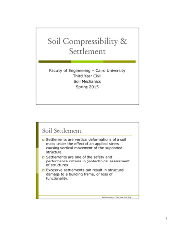
Geosynthetic Reinforced SoilIntegrated Bridge SystemInterim Implementation GuidePUBLICATION NO. FHWA-HRT-11-026Research, Development, and TechnologyTurner-Fairbank Highway Research Center6300 Georgetown PikeMcLean, VA 22101-2296JANUARY 2011
FOREWORDGeosynthetic Reinforced Soil (GRS) technology consists of closely spaced layers of geosyntheticreinforcement and compacted granular fill material. GRS has been used for a variety of earthworkapplications since the U.S. Forest Service first used it to build walls for roads in steep mountainterrain in the 1970s. Since then, the technology has evolved into the GRS Integrated BridgeSystem (IBS), a fast, cost-effective method of bridge support that blends the roadway into thesuperstructure. GRS-IBS includes a reinforced soil foundation, a GRS abutment, and a GRSintegrated approach. The application of IBS has several advantages. The system is easy to design andeconomically construct. It can be built in variable weather conditions with readily available labor,materials, and equipment and can easily be modified in the field. This method has significant valuewhen employed for small, single-span structures meeting the criteria described in this manual.As a result of the demonstrated performance of GRS-IBS, the technology was selected for theFederal Highway Administration’s (FHWA) Every Day Counts initiative, aimed at acceleratingimplementation of proven, market-ready technologies. This manual is the first in a two-part seriesand outlines the design and construction of GRS-IBS. The second document is a synthesis reportto substantiate the design method. Both documents are a collaboration between many disciplineswithin FHWA: geotechnical, structural, hydraulic, maintenance, and pavement engineering.Jorge Pagán-OrtizDirector, Office of InfrastructureResearch and DevelopmentNoticeThis document is disseminated under the sponsorship of the U.S. Department of Transportationin the interest of information exchange. The U.S. Government assumes no liability for the useof the information contained in this document. This report does not constitute a standard,specification, or regulation.The U.S. Government does not endorse products or manufacturers. Trademarks ormanufacturers’ names appear in this report only because they are considered essential to theobjective of the document.Quality Assurance StatementThe Federal Highway Administration (FHWA) provides high-quality information to serveGovernment, industry, and the public in a manner that promotes public understanding. Standardsand policies are used to ensure and maximize the quality, objectivity, utility, and integrity of itsinformation. FHWA periodically reviews quality issues and adjusts its programs and processes toensure continuous quality improvement.
TECHNICAL REPORT DOCUMENTATION PAGE1. Report No.2. Government Accession No.FHWA-HRT-11-0264. Title and SubtitleGeosynthetic Reinforced Soil Integrated Bridge System, InterimImplementation Guide3. Recipient’s Catalog No.5. Report DateJanuary 20116. Performing Organization Code:7. Author(s)8. Performing Organization Report No.Michael Adams, Jennifer Nicks, Tom Stabile, Jonathan Wu,Warren Schlatter, and Joseph Hartmann9. Performing Organization Name and Address10. Work Unit No.Office of Infrastructure Research and DevelopmentFederal Highway Administration11. Contract or Grant No.6300 Georgetown PikeMcLean, VA 2218113. Type of Report and Period Covered12. Sponsoring Agency Name and AddressFederal Highway AdministrationU.S. Department of Transportation14. Sponsoring Agency Code1200 New Jersey Avenue, SEWashington, DC 2059015. Supplementary NotesThe FHWA Contracting Officer’s Technical Representative (COTR) was Mike Adams, HRDS-40.16. AbstractThis manual outlines the state-of-the-art and recommended practice for designing and constructing GeosyntheticReinforced Soil (GRS) technology for the application of the Integrated Bridge System (IBS). The procedurespresented in this manual are based on 40 years of State and Federal research focused on GRS technology asapplied to abutments and walls.This manual was developed to serve as the first in a two-part series aimed at providing engineers with thenecessary background knowledge of GRS technology and its fundamental characteristics as an alternative toother construction methods. The manual presents step-by-step guidance on the design of GRS-IBS. Analyticaland empirical design methodologies in both the Allowable Stress Design (ASD) and Load and Resistance FactorDesign (LRFD) formats are provided. Material specifications for standard GRS-IBS are also provided. Detailedconstruction guidance is presented along with methods for the inspection, performance monitoring, maintenance,and repair of GRS-IBS. Quality assurance and quality control procedures are also covered in this manual.The second part of this series (FHWA-HRT-11-027) is a synthesis report that covers the background of GRS-IBSand provides other supporting information to substantiate the design method.17. Key Words18. Distribution StatementGeosynthetic Reinforced Soil (GRS), Integrated Bridge System(IBS), Design, Construction, Performance test, Geosynthetic,material specifications, Quality assurance, Quality control19. Security Classif. (of this report) 20. Security Classif. (of this page)21. No. of Pages22. PriceUnclassifiedUnclassified169Form DOT F 1700.7 (8-72)Reproduction of completed page authorized
SI* (MODERN METRIC) CONVERSION FACTORSAPPROXIMATE CONVERSIONS TO SI UNITSSymbolWhen You KnowinftydmiinchesfeetyardsmilesMultiply ByLENGTH25.40.3050.9141.61To quare millimeterssquare meterssquare metershectaressquare kilometersmmm2m2ha2kmAREA2inft2yd2ac2misquare inchessquare feetsquare yardacressquare miles645.20.0930.8360.4052.59fl ozgalft33ydfluid ouncesgallonscubic feetcubic yardsozlbTouncespoundsshort tons (2000 028cubic meters0.765cubic meters3NOTE: volumes greater than 1000 L shall be shown in mmLLm33mMASS28.350.4540.907gramskilogramsmegagrams (or "metric ton")TEMPERATURE (exact degrees)F5 (F-32)/9or (F-32)/1.8gkgMg (or orcepoundforce per square inchFORCE and PRESSURE or STRESS4.456.89newtonskilopascalsNkPaAPPROXIMATE CONVERSIONS FROM SI UNITSSymbolWhen You KnowMultiply 2mm2ha2kmsquare millimeterssquare meterssquare metershectaressquare kilometersmLLm33mmillilitersliterscubic meterscubic metersgkgMg (or "t")gramskilogramsmegagrams (or "metric ton")oCelsius0.0393.281.090.621To FindSymbolinchesfeetyardsmilesinftydmisquare inchessquare feetsquare yardsacressquare milesin22ftyd2ac2mifluid ouncesgallonscubic feetcubic yardsfl ozgalft33ydouncespoundsshort tons (2000 .26435.3141.307MASS0.0352.2021.103TEMPERATURE (exact degrees)C1.8C 9290.2919FORCE and PRESSURE or STRESS0.2250.145poundforcepoundforce per square inchlbf2lbf/in*SI is the symbol for the International System of Units. Appropriate rounding should be made to comply with Section 4 of ASTM E380.(Revised March 2003)ii
TABLE OF CONTENTSCHAPTER 1. GEOSYNTHETIC REINFORCED SOIL INTEGRATED BRIDGESYSTEM .11.1. INTRODUCTION.11.2 BENEFITS OF GRS-IBS .3CHAPTER 2. NOTATION, ABBREVIATIONS, AND TERMINOLOGY.52.1 NOTATION .52.2 ABBREVIATIONS .112.3 TERMINOLOGY .12CHAPTER 3. MATERIALS .153.1 INTRODUCTION.153.2 FACING ELEMENTS.153.3 BACKFILL MATERIAL.173.3.1 GRS Abutment Backfill .173.3.2 RSF Backfill.203.3.3 Integrated Approach Backfill .203.4 GEOSYNTHETIC .203.5 MISCELLANEOUS MATERIALS .23CHAPTER 4. DESIGN METHODOLOGY FOR GRS-IBS .254.1 OVERVIEW OF GRS-IBS DESIGN METHOD .254.2 BASIC DESIGN STEPS FOR GRS-IBS .274.3 GRS-IBS DESIGN GUIDELINES .284.3.1 Step 1—Establish Project Requirements .284.3.2 Step 2—Perform a Site Evaluation .294.3.3 Step 3—Evaluate Project Feasibility .304.3.4 Step 4—Determine Layout of GRS-IBS.304.3.5 Step 5—Calculate Applicable Loads .354.3.6 Step 6—Conduct an External Stability Analysis .394.3.7 Step 7—Conduct Internal Stability Analysis .444.3.8 Step 8—Implement Design Details .504.3.9 Step 9—Finalize Material Quantities and Layout .534.4 DESIGN EXAMPLE: BOWMAN ROAD BRIDGE, DEFIANCE COUNTY, OH . 544.4.1 Step 1—Establish Project Requirements .544.4.2 Step 2—Site Evaluation .564.4.3 Step 3—Evaluate Project Feasibility .584.4.4 Step 4—Determine Layout of GRS-IBS.584.4.5 Step 5—Calculate Loads.594.4.6 Step 6—Conduct an External Stability Analysis .604.4.7 Step 7—Conduct Internal Stability Analysis .634.4.8 Step 8—Implement Design Details .704.4.9 Step 9—Finalize Material Quantities and Layout .70iii
CHAPTER 5. SPECIAL REQUIREMENTS FOR HYDRAULIC AND SEISMICCONDITIONS .715.1 INTRODUCTION.715.2 HYDRAULIC DESIGN.715.3 HYDRAULIC DESIGN CONSIDERATIONS .715.4 SEISMIC DESIGN .735.5 IMPACT EVENTS .73CHAPTER 6. IN-SERVICE PERFORMANCE .756.1 INTRODUCTION.756.2 DEFORMATIONS .756.3 THERMAL CYCLES.786.4 MONITORING FOR SCOUR.78CHAPTER 7. CONSTRUCTION .797.1 INTRODUCTION.797.2 LABOR AND EQUIPMENT .807.2.1 Labor Requirements .807.2.2 Tool and Equipment Requirements .807.3 SITE PREPARATION .827.3.1 Site Layout .827.3.2 Excavation.827.3.3 Placement of Abutment Behind Existing Substructure .837.4 RSF .857.5 COMPACTION .877.5.1 Compaction Procedure .887.6 REINFORCEMENT.887.6.1 Operating Equipment on Geosynthetic Reinforcement .907.6.2 Bearing Reinforcement Bed .907.6.3 Superelevation.917.7 WALL FACE .917.7.1 Leveling Course .927.7.2 Setting the CMU Block.927.7.3 Wall Face Alignment .927.7.4 Block Alignment for Battered Walls .937.7.5 Superelevation.947.7.6 Wall Corners .957.7.7 Top of Facing Wall .967.8 BEAM SEAT .977.8.1 Beam Seat Procedure .997.8.2 Setback .1007.8.3 Aluminum Flashing .1017.8.4 CIP or Precast Footing .1017.9 PLACEMENT OF SUPERSTRUCTURE.1017.9.1 Crane Position on GRS Mass.1027.9.2 Reinforcement of Beam Seat .1027.9.3 Setting Superstructure on Beam Seat (Without CIP Footing) .1027.9.4 Wing Walls and Parapets .103iv
7.10 APPROACH INTEGRATION .1037.10.1 Wrapped Reinforcement Layers on Sides.1067.10.2 Preloading .1067.10.3 Paving .1067.10.4 Guardrail Post .1077.11 SITE DRAINAGE.107CHAPTER 8. IN-SERVICE INSPECTION, MAINTENANCE, AND REPAIR .1098.1 INTRODUCTION.1098.2 IN-SERVICE INSPECTION .1098.3 MAINTENANCE .1108.4 REPAIR .111CHAPTER 9. QUALITY CONTROL AND QUALITY ASSURANCE .1159.1 INTRODUCTION.1159.2 ROLE OF THE CONTRACTOR .1159.3 TESTING .1159.3.1 Laboratory Testing .1159.3.2 Field Testing .1169.4 CONSTRUCTION INSPECTION .1169.4.1 Materials .1169.4.2 Equipment .1179.4.3 Project Layout .1179.4.4 Construction Activities .1179.5 DOCUMENTATION.1199.5.1 Compliance Documentation.1199.5.2 Record Drawings .1199.6 CONTRACTING METHODS.1199.6.1 Performance Method .1209.6.2 Procedural Method .1209.6.3 Contractor Submittals .1229.7 PROJECT DRAWINGS AND DOCUMENTS .122APPENDIX A. IN-SERVICE GRADATIONS .123APPENDIX B. PERFORMANCE TEST PROCEDURE .125B.1 PERFORMANCE TEST OVERVIEW .125B.2 PERFORMANCE TEST EXAMPLE: VEGAS MINI-PIER .125B.3 PERFORMANCE TEST EXAMPLE: DEFIANCE COUNTYPERFORMANCE TEST .130APPENDIX C. LRFD DESIGN PROCEDURE .135C.1 INTRODUCTION.135C.2 GRS-IBS DESIGN GUIDELINES .136C.2.1 Step 6—Conduct an External Stability Analysis .137C.2.2 Step 7—Conduct Internal Stability Analysis .139v
C.3 DESIGN EXAMPLE (LRFD): BOWMAN ROAD BRIDGE,DEFIANCE COUNTY, OH .141C.3.6 Step 6—Conduct an External Stability Analysis .141C.3.7 Step 7—Conduct Internal Stability Analysis .143C.3.8 Step 8—Implement Design Details .147APPENDIX D. TYPICAL GRS-IBS WORKING DRAWINGS .149D.1 SINGLE-PAGE PLAN SHEET .149D.2 ESTIMATED QUANTITIES AND GENERAL NOTES .150D.3 PROJECT PLAN AND PROFILE.151D.4 GRS ABUTMENT DETAILS .152D.5 SITE PLAN .153ACKNOWLEDGEMENTS .155REFERENCES.157vi
LIST OF FIGURESFigure 1. Illustration. Typical GRS-IBS cross section .2Figure 2. Illustration. GRS walls with different facings .15Figure 3. Photo. Split face CMU blocks .16Figure 4. Photo. Detail view of split face CMU blocks .16Figure 5. Photo. Sample of VDOT 21-A gravel .19Figure 6. Photo. Sample of AASHTO No. 89 gravel .20Figure 7. Illustration. Geosynthetic roll direction .21Figure 8. Photo. Bitumen coating on concrete beam ends .23Figure 9. Chart. Steps for GRS-IBS design .28Figure 10. Photo. Bridge seat and setback distances .31Figure 11. Illustration. Clear space distance .32Figure 12. Illustration. RSF dimensions .33Figure 13. Illustration. Reinforcement schedule for a GRS abutment .34Figure 14. Illustration. Vertical and lateral pressures on a GRS abutment.35Figure 15. Illustration. Boussinesq load distribution with depth for a strip load.37Figure 16. Illustration. Internal lateral stress in GRS abutment wall due to bridge loading .38Figure 17. Illustration. External stability: direct sliding .40Figure 18. Illustration. External stability: bearing capacity .40Figure 19. Illustration. External stability: global stability .40Figure 20. Graph. Design envelope for vertical capacity and strain at 8-inch reinforcementspacing .45Figure 21. Illustration. Lateral deformation of a GRS structure .48Figure 22. Illustration. Typical cross section of a GRS wing wall .50Figure 23. Illustration. Typical cross section of a GRS abutment face wall .51Figure 24. Photo. Guardrail lay-down distance .52Figure 25. Photo. GRS abutment and wing walls built around core of native soil .52Figure 26. Illustration. Top view of Bowman Road Bridge showing the bridge, abutments,and wing walls .54Figure 27. Illustration. Aerial view of the existing site with the planned Bowman RoadBridge superimposed .55Figure 28. Illustration. Schematic of the west abutment for Bowman Road Bridge .56Figure 29. Illustration. Schematic of the east abutment for Bowman Road Bridge .56Figure 30. Illustration. Reinforcement schedule and RSF dimensions for Bowman Road Bridge .59Figure 31. Screenshot. ReSSA results for global stability for Bowman Road Bridge .63Figure 32. Graph. Stress-strain curve for Bowman Road Bridge showing ultimate capacity .64Figure 33. Graph. Vertical strain for Bowman Road Bridge .65Figure 34. Illustration. Lateral pressure due to the bridge load .68Figure 35. Illustration. Secondary reinforcement for superelevation at Bowman Road Bridge . 70Figure 36. Illustration. Typical cross section for sloping rock (adapted) .72Figure 37. Illustration. Survey level method for superstructure and wall settlement .76Figure 38. Photo. Location of survey targets on Tiffin River Bridge, Defiance County, OH .77Figure 39. Photo. Location of total station reference pole .77Figure 40. Photo. Typical labor crew with centrally located track hoe .80Figure 41. Photo. Cut slope of retained soil.82vii
Figure 42. Photo. Horseshoe-shaped excavation with native soil still intact in middle .83Figure 43. Photo. GRS-IBS built behind an existing concrete abutment .84Figure 44. Illustration. Cross section of GRS-IBS built behind an existing concrete abutment . 84Figure 45. Photo. Building the RSF behind an existing abutment.85Figure 46. Photo. RSF excavation below stream level .85Figure 47. Photo. RSF cut preparation.86Figure 48. Photo. Encapsulation of fill in RSF .86Figure 49. Photo. Placement of wall block on wrapped RSF .87Figure 50. Illustration. Typical reinforcement zones .89Figure 51. Reinforcement rolled out parallel to wall face .89Figure 52. Illustration. Superelevation reinforcement schedule .91Figure 53. Photo. Superelevation reinforce
System (IBS), a fast, cost-effective method of bridge support that blends the roadway into the superstructure. GRS-IBS includes a reinforced soil foundation, a GRS abutment, and a GRS integrated approach. The application of IBS has seve ral advantages. The system is easy to design and economically construct.