Transcription
APNIC eLearning:MPLS L3 VPNIssue Date: 07 July 2015Revision:2.0
Agenda MPLS VPN VRF RD & RT Control Plane of MPLS L3VPN Data Plane of MPLS L3VPN Configuration Example2
MPLS VPN Models33
Advantages of MPLS Layer-3 VPN Scalability Security Easy to Create Flexible Addressing Integrated Quality of Service (QoS) Support Straightforward Migration4
MPLS L3VPN TopologyCEVPNAVPNBPPPECEPECEVPNBMPLS NetworkPPVPNACE PE: Provider Edge Router P : Provider Router CE: Customer Edge Router5
Virtual Routing and Forwarding Instance Virtual routing and forwarding table– On PE router– Separate instance of routing (RIB) and forwarding table A VRF defines the VPN membership of a customer site attached to a PEdevice. VRF associated with one or more customer interfacesVPNACEVRF APEMPLS BackboneCEVPNBVRF B6
Control Plane: Multi-Protocol BGP PE routers use MP-BGP to distribute VPN routes to eachother. MP-BGP customizes the VPN Customer RoutingInformation as per the Locally Configured VRF Informationat the PE using:– Route Distinguisher (RD)– Route Target (RT)– VPN Label7
What is RD Route distinguisher is an 8-octet field prefixed to thecustomer's IPv4 address. RD makes the customer’s IPv4address unique inside the SP MPLS network. RD is configured in the VRF at PEVPNv4 Address:Route Distinguisher (8 bytes)Example:Type 0Type 1100:1192.168.19.1:1IPv4 Address (4bytes)10.1.1.110.1.1.18
Route Advertisement: RD VPN customer IPv4 prefix is converted into a VPNv4 prefixby appending the RD to the IPv4 address PE devices use MP-BGP to advertise the VPNv4 addressVPNv4 Prefixes on PE:VRF A 100:1:10.1.1.0VPNA10.1.1.0/24CEVRF B 200:1:10.1.1.0VRF ARD: 100:1PEMPLS BackboneVPNB10.1.1.0/24CEVRF BRD: 200:19
What is RT Route Target is a BGP extended community attribute, isused to control VPN routes advertisement.Route Target (8 bytes)Example:Type 0Type 1100:1192.168.1.1:1 Two types of RT:– Export RT– Import RT10
Route Advertisement: RTVRF A:MP-iBGP update:200:1:10.1.1.0/24Ex RT: 200:1, 300:1VRF B:CECEVPNBVPNAMPLS NetworkVPNB10.1.1.0/24PE1CEPE2VPNACEImport RTImport RTExport RTVRF A100:1100:1VRF B200:1300:1200:1300:1Export RTVRF A100:1400:1500:1100:1400:1VRF B200:1200:111
Using RT to Configure VPN TopologiesIm RT: 100:10Ex RT: 100:10Im RT: 100:12Ex RT: 100:11Spoke SiteSiteIm RT: 100:10Ex RT: 100:10Im RT: 100:10Ex RT: 100:10SiteSiteIm RT: 100:10Ex RT: 100:10SiteFull MeshIn a full-mesh VPN, eachsite in the VPN cancommunicate with everyother site in that same VPN.Im RT: 100:12Ex RT: 100:11Im RT: 100:12Ex RT: 100:11Spoke SiteSpoke SiteHub Site Im RT: 100:11Ex RT: 100:12Hub SpokeIn a hub-and-spoke VPN, thespoke sites in the VPN cancommunicate only with the hubsites; they cannot communicatewith other spoke sites.12
VPN LabelVRF B:200:1:10.1.1.0/24MP-iBGP update:RT: 200:1, 300:1200:1:10.1.1.0/24Out Label: 100RT: 200:1, 300:1Local Label: 100CECEMP-iBGPVPNBVPNAVPNB10.1.1.0/24CEPE1MPLS NetworkPE2VPNACE PE adds the label to the NLRI field.13
Control Plane Walkthrough(1/2)3Site 1MP-iBGP Update:RD:10.1.1.0Next-Hop PE-1RT 200:1, Label 100Site 2CE110.1.1.0/242PPPPCE210.1.1.0/24Next-Hop CE-11PE1PE2MPLS Backbone1.PE1 receives an IPv4 update (eBGP/OSPF/ISIS/RIP/EIGRP)2.PE1 converts it into VPNv4 address and constructs the MP-iBGP UPDATE message–––3.Associates the RT values (export RT 200:1) per VRF configurationRewrites next-hop attribute to itselfAssigns a label (100); Installs it in the MPLS forwarding table.PE1 sends MP-iBGP update to other PE routers14
Control Plane Walkthrough(2/2)3Site 1MP-iBGP Update:RD:10.1.1.0Next-Hop PE-1RT 200:1, Label 1002PPPP4CE210.1.1.0/24Next-Hop CE-11Site 25CE110.1.1.0/2410.1.1.0/24Next-Hop PE-2PE1PE2MPLS Backbone4.PE2 receives and checks whether the RT 200:1 is locally configured as import RTwithin any VRF, if yes, then– PE2 translates VPNv4 prefix back to IPv4 prefix– Updates the VRF CEF table for 10.1.1.0/24 with label 1005.PE2 advertises this IPv4 prefix to CE2 (using whatever routing protocol)15
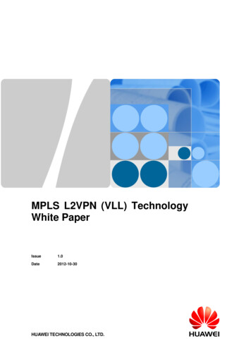
Control Plane: Tunnel face 32Eth0/050-1.1.1.1/32Eth0/125-Eth0PE1/1 Eth0/1Eth0/0Eth0/0L0:1.1.1.1/32P1LDPPE2P2MPLS Backbone LDP runs on the MPLS backbone network to build the public LSP. Thetunnel label is also called transport label or public label. Local label mapping are sent to connected nodes. Receiving nodesupdate forwarding table.16
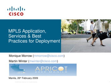
Data PlaneSite 110.1.1.0/24Site 2CE1P310.1.1.1IP PacketCE2P4PE1100PE210.1.1.1 P15010010.1.1.1IP PacketP210.1.1.12510010.1.1.1MPLS Packet PE2 imposes two labels for each IP packet going to site2– Tunnel label is learned via LDP; corresponds to PE1 address– VPN label is learned via BGP; corresponds to the VPN address P1 does the Penultimate Hop Popping (PHP) PE1 retrieves IP packet (from received MPLS packet) and forwards it to CE1.17
Configuration Example Task: Configure MPLS L3VPN on Cisco IOS (Version 15.2) tomake the following CEs communication with each other. Prerequisite configuration:– 1. IP address configuration on PE & P routers– 2. IGP configuration on PE & P routers Make sure all the routers in public network can reach each 324.4.4.4/32200.1.1.0/24CE1VPNAPE1P1P2PE2CE2MPLS Network18
Configure MPLS & LDP Configuration steps:– 1. Configure MPLS and LDP on PE & P routersip cefmpls ldp router-id loopback 0interface ethernet1/0mpls ipmpls label protocol ldpinterface ethernet1/1mpls ipmpls label protocol ldp19
Configure VRF Configuration steps:– 2. Configure VRF instance on PE routersvrf definition VPNArd 100:10route-target export 100:10route-target import 100:10!address-family ipv4exit-address-family!– bind PE-CE interface under VRFinterface FastEthernet0/0vrf forwarding VPNAip address 10.1.1.1 255.255.255.25220
Configure MP-iBGP Configuration steps:– 3. Enable MP-iBGP neighbors in vpnv4 address-family on PE routersrouter bgp 100neighbor 4.4.4.4 remote-as 100neighbor 4.4.4.4 update-source loopback 0!address-family vpnv4neighbor 4.4.4.4 activateneighbor 4.4.4.4 send-community bothexit-address-family!21
Configure PE-CE eBGP Neighbour Configuration steps:– 4. Adding PE-CE eBGP neighbour in VRF context of BGP on PErouter bgp 100address-family ipv4 vrf VPNAneighbor 10.1.1.2 remote-as 65001neighbor 10.1.1.2 activateexit-address-family!Adding PE-CE eBGP neighbour in BGP on CErouter bgp 65001neighbor 10.1.1.1 remote-as 100!address-family ipv4network 100.1.1.0 mask 255.255.255.0neighbor 10.1.1.1 activateexit-address-family!ip route 100.1.1.0 255.255.255.0 null 022
Verify Results – VRF Routing Table Check the routes of VRF VPNA on PE.PE1#show bgp vpnv4 unicast vrf VPNABGP table version is 4, local router ID is 1.1.1.1Status codes: s suppressed, d damped, h history, * valid, best, i - internal,r RIB-failure, S Stale, m multipath, b backup-path, f RT-Filter,x best-external, a additional-path, c RIB-compressed,Origin codes: i - IGP, e - EGP, ? - incompleteRPKI validation codes: V valid, I invalid, N Not foundNetworkNext HopMetric LocPrf Weight PathRoute Distinguisher: 100:10 (default for vrf VPNA)* 100.1.1.0/2410.1.1.200 65001 i* i 200.1.1.04.4.4.401000 65002 i23
Verify Results – VPN Reachability CE can learn the routes from each other:CE2#show ip route.10.0.0.0/8 is variably subnetted, 2 subnets, 2 masksC10.1.2.0/30 is directly connected, FastEthernet0/1L10.1.2.2/32 is directly connected, FastEthernet0/1100.0.0.0/24 is subnetted, 1 subnetsB100.1.1.0 [20/0] via 10.1.2.1, 00:38:26200.1.1.0/24 is variably subnetted, 2 subnets, 2 masksS200.1.1.0/24 is directly connected, Null0C200.1.1.1/32 is directly connected, Loopback124
Please remember to fill out thefeedback form:- Survey LinkSlides are available fordownload from APNIC FTP.25
APNIC Helpdesk Chat
Thank You!END OF SESSION27
LDP runs on the MPLS backbone network to build the public LSP. The tunnel label is also called transport label or public label. Local label mapping are sent to connected nodes. Receiving nodes update forwarding table. 16 PE1 PE2 P1 P2 MPLS Backbone L0:1.1.1.1/32 Local Label Prefix Out Interface Out Label Pop- Label 1.1.1.1/32 -