Transcription
MPLS Virtual PrivateNetworksA review of the implementation options for MPLS VPNs including theongoing standardization work in the IETF MPLS Working GroupPaul Brittain, pjb@metaswitch.comAdrian Farrel, afarrel@movaz.comFirst issued November 2000100 Church Street, Enfield, England, EN2 6BQ www.metaswitch.com
Table of Contents1.Introduction .12.Background. 22.1 Introduction to MPLS. 22.1.1 Label Distribution . 42.1.2 Tunnels and Label Stacks . 43.2.2Overview of VPN Requirements. 62.3Summary of VPN Types . 7MPLS For VPNs . 83.1 Elements of an MPLS VPN solution . 83.1.1 LSP Tunnels . 83.1.2 VPN Traffic Engineering . 93.1.3 Network Management .123.2 Applicability of MPLS to VPN Types.123.2.1 MPLS for VLL.123.2.2 MPLS for VPLS .133.2.3 MPLS for VPRN .143.2.4 MPLS for VPDN.144.5.VPN Peer and Route Discovery. 154.1Manual Configuration .164.2Emulated LAN .164.3Overlay IGP or EGP . 174.4Directory.184.5VPRN Route Configuration .184.6Management Information Bases .19VPN Multiplexing and Class of Service. 205.1Class Of Service Options . 205.2Multiplexing VPN and CoS .216.Distributing Labels For Nested LSPs . 237.MPLS VPN Security . 268.VPN Implementation Models .279.Standardization Efforts . 299.1Work to Date. 299.2 Outstanding Items . 299.2.1 VPN ID . 29Copyright Metaswitch Networks. Confidential Page i
9.2.29.2.39.2.49.2.59.2.69.2.7Overall Approach to MPLS VPNs . 30Routing Protocol Overlays . 30Directory Schema. 30MPLS TE Extensions . 30Management Information Bases . 30Other Items.3110.Summary. 3211.Glossary . 3312.References . 3613.About Metaswitch . 38Copyright Metaswitch Networks. Confidential Page ii
1. IntroductionHistorically, private WANs were provisioned using dedicated leased line connections, each lineproviding a point-to-point connection between two customer sites. Such networks are expensive toput in place, especially if the connections between sites need to support some level of redundancy.There is also no scope in such a system to share under-utilized bandwidth across several customersor, conversely, to increase the bandwidth available between particular sites dynamically in order tomeet short-term peaks in demand.Virtual Private Networks (VPNs) are a method of interconnecting multiple sites belonging to acustomer using a Service Provider (SP) backbone network in place of dedicated leased lines. Eachcustomer site is directly connected to the SP backbone. The SP can offer a VPN service moreeconomically than if dedicated private WANs are built by each individual customer because the SPcan share the same backbone network resources (bandwidth, redundant links) between manycustomers. The customer also gains by outsourcing the complex task of planning, provisioning andmanaging a geographically distributed network to the SP.Unfortunately, existing VPN solutions are not all interoperable and may be tied to one equipmentvendor and/or a single SP. This has created strong interest in IP-based VPNs running over the publicInternet using standards-based interoperable implementations that work across multiple SPs.Many of these IP-based solutions require IP address-mapping or double encapsulation using two IPheaders. This can require complex configuration management and requires additional processing atthe entry to and exit from the SP’s networks.The new Internet technology, Multi-Protocol Label Switching (MPLS) forwards data using labels thatare attached to each data packet. Intermediate MPLS nodes do not need to look at the content of thedata in each packet. In particular the destination IP addresses in the packets are not examined,which enables MPLS to offer an efficient encapsulation mechanism for private data traffic traversingthe SP backbone. MPLS can, therefore, provide an excellent base technology for standards-basedVPNs.This white paper reviews the requirements placed on a base technology for VPNs, how MPLS meetsthese requirements, and the state of the ongoing standardization efforts within the IETF. AlternativeVPN technologies are touched on briefly, but a detailed review of such alternatives is outside thescope of this paper.The structure of this white paper is shown in the table of contents. Readers who are already familiarwith RFC 2764 and MPLS concepts, in particular tunnels and label stacks, may prefer to skip to theMPLS For VPNs section.Copyright Metaswitch Networks. Confidential Page 1
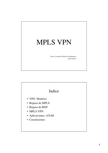
2. Background2.1 Introduction to MPLSMulti-Protocol Label Switching (MPLS) is a new technology that will be used by many future corenetworks, including converged data and voice networks. MPLS does not replace IP routing, but willwork alongside existing and future routing technologies to provide very high-speed data forwardingbetween Label-Switched Routers (LSRs) together with reservation of bandwidth for traffic flows withdiffering Quality of Service (QoS) requirements.MPLS enhances the services that can be provided by IP networks, offering scope for TrafficEngineering, guaranteed QoS and Virtual Private Networks (VPNs).The basic operation of an MPLS network is shown in the diagram below.LSR DEgressZ47LSR AIngress21LSR BX1711LSR CEgressYFig.1: Two LSPs in an MPLS NetworkMPLS uses a technique known as label switching to forward data through the network. A small,fixed-format label is inserted in front of each data packet on entry into the MPLS network. At eachhop across the network, the packet is routed based on the value of the incoming interface and label,and dispatched to an outwards interface with a new label value.Copyright Metaswitch Networks. Confidential Page 2
The path that data follows through a network is defined by the transition in label values, as the labelis swapped at each LSR. Since the mapping between labels is constant at each LSR, the path isdetermined by the initial label value. Such a path is called a Label Switched Path (LSP).At the ingress to an MPLS network, each packet is examined to determine which LSP it should useand hence what label to assign to it. This decision is a local matter but is likely to be based onfactors including the destination address, the quality of service requirements and the current state ofthe network. This flexibility is one of the key elements that make MPLS so useful.The set of all packets that are forwarded in the same way is known as a Forwarding EquivalenceClass (FEC). One or more FECs may be mapped to a single LSP.The diagram shows two data flows from host X: one to Y, and one to Z. Two LSPs are shown. LSR A is the ingress point into the MPLS network for data from host X. When it receivespackets from X, LSR A determines the FEC for each packet, deduces the LSP to use and addsa label to the packet. LSR A then forwards the packet on the appropriate interface for theLSP. LSR B is an intermediate LSR in the MPLS network. It simply takes each labeled packet itreceives and uses the pairing {incoming interface, label value} to decide the pairing{outgoing interface, label value} with which to forward the packet. This procedure can use asimple lookup table and, together with the swapping of label value and forwarding of thepacket, can be performed in hardware. This allows MPLS networks to be built on existinglabel switching hardware such as ATM and Frame Relay. This way of forwarding data packetsis potentially much faster than examining the full packet header to decide the next hop.In the example, each packet with label value 21 will be dispatched out of the interfacetowards LSR D, bearing label value 47. Packets with label value 17 will be re-labeled withvalue 11 and sent towards LSR C. LSR C and LSR D act as egress LSRs from the MPLS network. These LSRs perform the samelookup as the intermediate LSRs, but the {outgoing interface, label value} pair marks thepacket as exiting the LSP. The egress LSRs strip the labels from the packets and forwardthem using layer 3 routing.So, if LSR A identifies all packets for host Z with the upper LSP and labels them with value 21, theywill be successfully forwarded through the network.Note that the exact format of a label and how it is added to the packet depends on the layer 2 linktechnology used in the MPLS network. For example, a label could correspond to an ATM VPI/VCI, aFrame Relay DLCI, or a DWDM wavelength for optical networking. For other layer 2 types (such asEthernet and PPP) the label is added to the data packet in an MPLS “shim” header, which is placedbetween the layer 2 and layer 3 headers.Copyright Metaswitch Networks. Confidential Page 3
2.1.1 Label DistributionIn order that LSPs can be used, the forwarding tables at each LSR must be populated with themappings from {incoming interface, label value} to {outgoing interface, label value}. This process iscalled LSP setup, or Label Distribution.The MPLS architecture document [13] does not mandate a single protocol for the distribution oflabels between LSRs. In fact it specifically allows multiple different label distribution protocols foruse in different scenarios, including the following. LDP [11]CR-LDP [10]RSVP [9]BGP4OSPFA detailed review of how these protocols are used for label distribution is outside the scope of thiswhite paper. For a comparative analysis of RSVP and CR-LDP, refer to the white paper MPLS TrafficEngineering: A choice of Signaling Protocols [1] from Metaswitch.Several different approaches to label distribution can be used depending on the requirements of thehardware that forms the MPLS network, and the administrative policies used on the network. Theunderlying principles are that an LSP is set up either in response to a request from the ingress LSR(downstream-on-demand), or pre-emptively by LSRs in the network, including the egress LSR(downstream unsolicited). It is possible for both to take place at once and for the LSP setup to meetin the middle.New ideas introduced by the IETF in the MPLS Generalized Signaling draft [14] also allow labels to bepushed from upstream to set up bi-directional LSPs.Alternatively, LSPs may be programmed as static or permanent LSPs by programming the labelmappings at each LSR on the path using some form of management such as SNMP control of theMIBs.2.1.2 Tunnels and Label StacksA key feature of MPLS, especially when considering VPNs, is that once the labels required for an LSPhave been exchanged between the LSRs that support the LSP, intermediate LSRs transited by theLSP do not need to examine the content of the data packets flowing on the LSP. For this reason, LSPsare often considered to form tunnels across all or part of the backbone MPLS network. A tunnelcarries opaque data between the tunnel ingress and tunnel egress LSRs.This means that the entire payload, including IP headers, may safely be encrypted without damagingthe ability of the network to forward data.Copyright Metaswitch Networks. Confidential Page 4
In Fig.1, both LSPs are acting as tunnels. LSR B forwards the packets based only on the labelattached to each packet. It does not inspect the contents of the packet or the encapsulated IPheader.An egress LSR may distribute labels for multiple FECs and set up multiple LSPs. Where these LSPsare parallel they can be routed, together, down a higher-level LSP tunnel between LSRs in thenetwork. Labeled packets entering the higher-level LSP tunnel are given an additional label to seethem through the network, and retain their first-level labels to distinguish them when they emergefrom the higher-level tunnel. This process of placing multiple labels on a packet is known as labelstacking and is shown in Fig.2.Label stacks allow a finer granularity of traffic classification between tunnel ingress and egressnodes than is visible to the LSRs in the core of the network, which need only route data on the basisof the topmost label in the stack. This helps to reduce both the size of the forwarding tables thatneed to be maintained on the core LSRs and the complexity of managing data forwarding across thebackbone.LSR ABackboneNetwork6LSR C17 6LSR D17 13X21 6LSR E21 13LSR B13YFig.2: Label Stacks across the backboneIn Fig.2, two LSPs between LSR A and LSR E, and between LSR B and LSR E, shown as red and bluelabels, are transparently tunneled across the backbone network in a single outer LSP between LSR Cand LSR E.At the ingress to the backbone network, LSR C routes both incoming LSPs down the LSP tunnel toLSR E, which is the egress from the backbone. To do this, it pushes an additional label onto the labelstack of each packet (shown in yellow). LSRs within the backbone, such as LSR D, are aware only ofthe outer tunnel, shown by the yellow labels. Note that the inner labels are unchanged as LSRs Cand D switch the traffic through the outer tunnel.At the egress of the outer tunnel, the top label is popped off the stack and the traffic is switchedaccording to the inner label. In the example shown, LSR E also acts as the egress for the inner LSPs,Copyright Metaswitch Networks. Confidential Page 5
so it pops the inner label too and routes the traffic to the appropriate host. The egress of the innerLSPs could be disjoint from E in the same way that LSR A and LSR B are separate from LSR C.Equally, an LSR can act as the ingress for both levels of LSP.A label stack is arranged with the label for the outer tunnel at the top and the label for the inner LSPat the bottom. On the wire (or fiber) the topmost label is transmitted first and is the only label usedfor routing the packet until it is popped from the stack and the next highest label becomes the toplabel.The bottom label of a stack (the red and blue labels in Fig.2) is usually taken from a per platformlabel space (the Global Label Space) as this allows the outer tunnel to be re-routed when necessary.(Re-routing of an outer tunnel may result in that outer tunnel being received at its egress through adifferent physical interface from the one originally used when the inner tunnel was set up. Thiscould lead to confusion about the interpretation of the lower label unless it is taken from a labelspace that is interpreted in the same way regardless of the incoming interface.)For MPLS networks based on ATM equipment, it is attractive to consider using the VPI as the outerlabel and the VCI as the inner label. However, this places constraints on the number of outer andinner labels that may be too restrictive for an SP that needs to support many thousands of tunnelsacross the backbone. An alternative in such cases is to carry the inner label in a shim header belowan outer VPI/VCI-based label. Although this method of label stacking in ATM means that the labelstack cannot be fully implemented in standard ATM hardware, it does overcome other problems, notleast of which is that some ATM hardware is incapable of performing VPI switching.2.2 Overview of VPN RequirementsRFC 2764 [4] defines a generic framework for IP-based VPNs, including the following requirementsfor a VPN solution. Opaque transport of data between VPN sites, because the customer may be using non-IPprotocols or locally administered IP addresses that are not unique across the SP network. Security of VPN data transport to avoid misdirection, modification, spoofing or snooping ofthe customer data. QoS guarantees to meet the business requirements of the customer in terms of bandwidth,availability and latency.In addition, the management model for IP-based VPNs must be sufficiently flexible to allow either thecustomer or the SP to manage a VPN. In the case where an SP allows one or more customers tomanage their own VPNs, the SP must ensure that the management tools provide security against theactions of one customer adversely affecting the level of service provided to other customers.Copyright Metaswitch Networks. Confidential Page 6
2.3 Summary of VPN TypesFour types of VPN are defined in RFC 2764. Virtual Leased Lines (VLL) provide connection-oriented point-to-point links betweencustomer sites. The customer perceives each VLL as a dedicated private (physical) link,although it is, in fact, provided by an IP tunnel across the backbone network The IPtunneling protocol used over a VLL must be capable of carrying any protocol that thecustomer uses between the sites connected by that VLL. Virtual Private LAN Segments (VPLS) provide an emulated LAN between the VPLS sites. Aswith VLLs, a VPLS VPN requires use of IP tunnels that are transparent to the protocols carriedon the emulated LAN. The LAN may be emulated using a mesh of tunnels between thecustomer sites or by mapping each VPLS to a separate multicast IP address. Virtual Private Routed Networks (VPRNs) emulate a dedicated IP-based routed networkbetween the customer sites. Although a VPRN carries IP traffic, it must be treated as aseparate routing domain from the underlying SP network, as the VPRN is likely to make useof non-unique customer-assigned IP addresses. Each customer network perceives itself asoperating in isolation and disjoint from the Internet – it is, therefore, free to assign IPaddresses in whatever manner it likes. These addresses must not be advertised outside theVPRN since they cannot be guaranteed to be unique more widely than the VPN itself. Virtual Private Dial Networks (VPDNs) allow customers to outsource to the SP theprovisioning and management of dial-in access to their networks. Instead of each customersetting up their own access servers and using PPP sessions between a central location andremote users, the SP provides a shared, or very many shared access servers. PPP sessionsfor each VPDN are tunneled from the SP access server to an access point into eachcustomer’s network, known as the access concentrator.The last of these VPN types is providing a specialized form of access to a customer network. The IETFhas specified the Layer 2 Tunneling Protocol (L2TP), which is explicitly designed to provide theauthentication and multiplexing capabilities required for extending PPP sessions from a customer’sL2TP Access Concentrator (LAC) to the SP’s L2TP Network Server (LNS).Copyright Metaswitch Networks. Confidential Page 7
3. MPLS For VPNsMPLS is rapidly emerging as a core technology for next-generation networks, in particular opticalnetworks. It also provides a flexible and elegant VPN solution based on the use of LSP tunnels toencapsulate VPN data. VPNs give considerable added value to the customer over and above a basicbest effort IP service, so this represents a major revenue-generating opportunity for SPs.The rest of this chapter gives an overview of the basic elements of an MPLS-based VPN solution andthe applicability of MPLS to different VPN types. Subsequent chapters examine the trickier aspectsof MPLS for VPNs in greater detail.3.1 Elements of an MPLS VPN solutionLet us consider how MPLS can provide a VPN solution by examining how it would work at severaldifferent levels. We start with the data forwarding mechanics and work our way up to the networkmanagement considerations.Different implementation models for MPLS-based VPNs imply different interactions between theseelements of a VPN solution. See the section VPN Implementation Models for further details.3.1.1 LSP TunnelsThe basis of any MPLS solution for VPNs is the use of LSP tunnels for forwarding data between SPedge routers that border on a given VPN. By labeling the VPN data as it enters such a tunnel, the LSRneatly segregates the VPN flows from the rest of the data flowing in the SP backbone. Thissegregation is key to enabling MPLS to support the following characteristics of a VPN tunnelingscheme, as identified in RFC 2764. Multiple protocols on the VPN can be encapsulated by the tunnel ingress LSR since the datatraversing an LSP tunnel is opaque to intermediate routers within the SP backbone. Multiplexing of traffic for different VPNs onto shared backbone links can be achieved byusing separate LSP tunnels (and hence separate labels) for each data source. Authentication of the LSP tunnel endpoint is provided by the label distribution protocols.See the section VPN Security for more details QoS for the VPN data can be assured by reserving network resources for the LSP tunnels.MPLS supports both Intserv and Diffserv. The implications of using each of these reservationstyles are examined in the next section.Copyright Metaswitch Networks. Confidential Page 8
Protection switching and automatic re-routing of LSP tunnels ensure that failure of a link orrouter that affects a VPN can be corrected without management intervention. Theseprotection mechanisms operate at several different levels, including refresh/keep-alivemessages on a hop-by-hop basis within the label distribution protocols, re-routing of LSPtunnels, pre-provisioning of alternative routes, and wavelength failure detection andmanagement for optical networks.VPN ALERLERLSRVPN AVPN BLSRLSRLERLERVPN BLSRVPN AFig.3: VPN Connectivity Using LSP TunnelsFigure 3 shows simple interconnection between five VPN sites belonging to two different VPNs. Atotal of four LSPs are required in this topology, one to connect the two sites in VPN B, and three toconnect the three sites in VPN A.3.1.2 VPN Traffic EngineeringAn LSP tunnel forms an excellent encapsulation scheme for VPN data flowing between two LSRs. Buthow do LSRs determine which LSPs to set up to provide connectivity for VPNs? In effect, how doLSRs decide which other LSRs provide access to the VPNs which they themselves serve? Even oncethis has been done, how should the different VPNs be mapped into LSP tunnels – a separate tunnelfor each VPN, or a single tunnel for all VPNs?Copyright Metaswitch Networks. Confidential Page 9
These are complex questions that do not have a single “right” answer. There is a number of factorsthat determine what VPN Traffic Engineering (TE) scheme best suits the performance and scalabilityrequirements of a particular customer and their SP. Identifying VPN peersThis is the first problem facing an LSR that has been configured to support a VPN. Thesimplest scheme is to use explicit manual configuration of the VPN peers. This is thetraditional solution providing obvious and deterministic control of resources and security,but it does not scale well as the size and complexity of the VPN increases.Alternative schemes automate the process of discovering VPN peers using a directory or byoverlaying VPN membership information on one or more routing protocols used on the SPnetwork. This greatly simplifies the configuration task for a VPN since it means that each SPedge router need only be configured with information about the VPNs serviced by each of itscustomer interfaces. There is clearly a potential security trade-off here as rogue routers canpretend to give access to a VPN.In comparison, an IPSEC-based solution [15] requires that each SP Edge router also beconfigured with security attributes for each peer in the VPN, which greatly increases theconfiguration complexity.Several options for identifying VPN peers are examined in the VPN Peer and Route Discoverysection below. See MPLS VPN Security for further discussion of IPSEC. Multiplexing VPNs on an LSPAlthough LSRs in the core of the SP network do not have to examine the data flowing on VPNLSP tunnels, they are still aware of the existence of these tunnels. This can represent ascalability problem if a separate mesh of LSP tunnels is used for each VPN, because the coreLSRs must at least maintain a forwarding table entry and associated resource reservation foreach tunnel.If the SP supports thousands of VPN customers, the core LSRs could be required to maintainmillions of LSPs. This is the same problem faced by VPN solutions based on ATM or Framerelay technology. Depending on the network topology, this large number of labels may alsobe beyond the capacity of the LSR switching hardware.An alternative approach is to multiplex the traffic from multiple VPNs that share the sameingress and egress SP edge routers within a single LSP tunnel between those LSRs. This isachieved using label stacks, with a single outer tunnel set up across the core and an innerLSP that identifies the VPN for which the data is bound. The lower label in the stack is knownonly to the ingress and egress LSRs.Copyright Metaswitch Networks. Confidential Page 10
This use of label stacks reduces the number of LSP tunnels exposed to the network core, butit ties VPNs together. The multiplexed VPNs cannot be routed separately or given differentprioritization or drop priority by the core LSRs. The VPNs must also share a single networkresource reservation within the network core, which may make it harder for the SP toguarantee the SLA for each individual customer.In figure 4, two VPNs are connected across the MPLS network between a pair of LERs. Thetraffic for each VPN is carried on a distinct LSP shown as a red and a green line in thediagram. These two VPNs are nested within an outer LSP shown in blue.VPN AVPN ALERLSRLSRLERVPN BVPN BMPLS NetworkFig.4: Nested LSPs Providing VPN Connectivity Separating QoS classesMultiplexing VPNs within a single tunnel helps to reduce the signaling load and forwardingtable size in the core LSRs as the number and size of the VPNs increase.However, once the data for multiple streams has been clustered together in a single LSP, it ishard to provide distinct management of the different flows. The encoding of an MPLS labelallows three bits to encode the Differentiated Services Control Point (DSCP). Thus a total ofeight classes of service (CoS) can be set for packets w
The basic operation of an MPLS network is shown in the diagram below. 21. 11. LSR A Ingress LSR B LSR C Egress LSR D Egress X Y Z 47 17 Fig.1: Two LSPs in an MPLS Network . MPLS uses a technique known as label switching to forward data through the network. A small, fixed-format label is inserted in front of each data packet on entry into the .