Transcription
X-Ray Security Inspection SystemUser's Manual
X-Ray Security Inspection SystemUser's Manual
Statement of Rights and ResponsibilitiesStatement of Rights and Responsibilities Anyone shall not do copy the print file of the manual or copy or spread theelectronic document of the manual without the written permission of the company. The company shall not undertake any responsibility for the damage of theequipment or the claim of Third Party caused by misuse. Because the document update fails to keep up with the software update, if there issome minor discrepancies, please understand.-I-
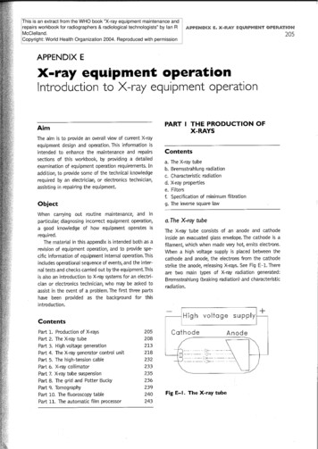
ForewordForewordThank you for using X-ray security inspection equipment:Dual-energy X-ray security inspection equipment is a new security inspection equipment whichmakes use of the penetrating power of X-ray to implement the rapid inspection of the packingbaggage and goods. The equipment is equipped with the advanced X-ray image detection systemand combines the advantages of the efficient semiconductor detector, digital image processingtechnology and computer image display so as to provide users with an efficient and reliable highquality image processing system with the service function. The equipment has enough hard diskcapacity which can store any number of high-definition images, and has the reliable automaticalarm function for the dangerous goods and drugs, operator training function, dangerous goodsinsertion function (TIP), network extending and interconnection function, automatic error check andmaintenance function, etc.; besides, It also adopts the simple humanized operation design so as tomake the user operation more convenient and quick.Purpose:This manual will help operators to operate X-Ray Security Inspection System correctly. Please readthis manual before the installation and operation of the product.Application:This manual is mainly suitable for the following people:Operators of X-Ray Security Inspection SystemAdministrators of X-Ray Security Inspection SystemMaintenance personnel of X-Ray Security Inspection System- II -
ContentsContentsStatement of Rights and Responsibilities. IForeword. IIChapter 1 Safety Warning Signs. 1Chapter 2 Safety Precautions for Operation. 2Chapter 3 Equipment Appearance and Special Keyboard. 33.1 Equipment Appearance. 33.2 Special Keyboard. 4Chapter 4 Equipment Operation. 84.1 Inspection before Boot. 84.2 Boot. . 94.3 Login. 104.4 Inspection of Goods. 114.5 Power OFF. 13Chapter 5 Operation of Drawing Reading. 145.1 Status Information Area. 155.2 Image Processing Function Area. 165.2.1 Color Image(CR)/BW Display(BW). 165.2.2 Image Local Enhancement (LE). 175.2.3 Enhancement of High Penetrating Power (HP). 175.2.4 Enhancement of Low Penetrating Power (LP). 185.2.5 Super Enhancement (GE). 185.2.6 Organics Exclusion (OS). 185. 2.7 Inorganic Exclusion (MS). 195.2.8 Negative (RS). 195.2.9 Brightening (BT). 195.2.10 Darkening (DK). 205.2.11 Gray-Level Scan (GS). 205.2.12 Image Magnification. 205.2.13 Pseudo-Color Processing (PC). 215.2.14 Suspicious Organics Enhancement Z7/Z8/Z9. 215.2.15 Alarm Sign Box of Suspicious Object. 225.2.16 Edge Enhancement (EE). 225.3 Operation Function Area. 235.3.1 Function Shortcut Keys. 235.3.2 Forward, Stop and Reverse. 235.3.3 Prev. and Next. 235.4 Menu and Image Navigation Area. 23- 3-
Contents5.4.1 Menu. 235.4.2 Calibration. 245.4.3 Status. 245.4.4 Image Navigation. 245.5 Image Display Area. 24Chapter 6 Menu Operation. 256.1 Logout. 256.2 Image Management. 266.3 Operator Management. 286.4 TIP (Dangerous Goods Insertion). 326.5 Equipment Diagnosis. 346.6 System Setting. 386.7 About. 43Chapter 7 Care and Maintenance. 457.1 External Cleaning of Equipment. 457.2 Clean-up of Photoelectric Sensor. 457.3 Display Clean-up. 457.4 Inspection of Conveyor. 467.5 Inspection of Lead Curtain at Access. 467.6 Inspection of X-Ray and Power Indicator Light. 467.7 Inspection of Emergency Stop Button. 46Chapter 8 Common Faults and Troubleshooting. 478.1 Key Switch Indicator Light Not On & Equipment Not Power-On. 478.2 Display Not On after System Power-on. 478.3 Conveyor Fails to Run. 488.4 Auto Shutdown during Equipment in Operation. 49Chapter 9 After-Sales Service. 509.1 After-Sales Service. 509.2 After-Sales Service Items. 51Packing & Acceptance List of Security Inspection Equipment. 52Security Inspection Product Quality Certificate.53Security Inspection Product Warranty. 54Repair Form of Security Inspection Product. 55Chapter 10 Attachments. 5610.1 Terminology. 5710.2 Specifications and Parameters Table of Typical Models. 5810.3 Cable Connection Block Diagram for Components of Equipment. 76Security Equipment project Acceptance Bill. .- 4-
Chapter 1 Safety Warning SignsChapter 1 Safety Warning SignsThe meaning and positions of the safety warning signs on the X-Ray SecurityInspection System are shown in Table 1-1.Table 1.1 Meanings of Safety SignsNo.Sign1Purpose or MeaningPositionFilm safety and radiationdanger signsLintel of accessSign for Goods Placement2[Remark: The sign for 150180Bsee 4.4 Inspection of Goods]Lintel of accessSign for forklift positionBelow thebottom sidepanel4Warning sign for strongcurrentExterior ofpower box5GND terminal signInternal GND ofequipment6Sign for X-Ray SourceX-ray source orsensor box7Sign for Moving PartsPresentBoth sides ofroller8Sign for Minding yourhandThe front ofthe console panel39EMERGENCYSign for emergency stop10POWERSign for Power Light11X-RAYSign for X-ray light12ALARMSign for alarm light-1-Near EmergencyStop buttonOn or Near thepower lightOn or near thex-ray lightOn or near thealarm light
-2-
Chapter 2 Safety Precautions for OperationChapter 2 Safety Precautions for Operation1. Before the operation of X-Ray Security Inspection System, the operator should receive thetraining related to the radiation protection according to the requirements of local laws andregulations.2. The installation and operation situations of X-Ray Security Inspection System should bereported to the relevant competent department in the location where the equipment use and theradiation safety inspection shall be conducted if necessary. Please regularly check the radiationprotection conditions of X-ray.3 The operators should know about regulations and requirements related to the radiation beforethe operation of X-Ray Security Inspection System.4. After the outage of the X- ray generator in the equipment for a long time, the preheating mustbe done according to the corresponding prompts of the running inspection station before theusage again in order to guarantee the service life of the X-ray generator.5. The operation and storage environment of X-Ray Security Inspection System should avoid theconductive dust, chemicals, etc.6. The operators should receive the necessary training on how to operate the equipment beforeoperation.7. Before supplying the power to the equipment, be sure that the power supply voltage of theequipment supplied on site should be consistent with the power supply voltage required of theequipment and simultaneously the power supply capacity shall not be lower than the workingpower of the equipment, as shown in the power supply parameters table of X-Ray SecurityInspection System.8. The equipment power supply should be in good grounding condition, and when the groundingconditions required are not satisfied, the equipment must not be operated.9. When the parts of the equipment need to be installed or replaced, please contact the professionalmaintenance personnel or the after-sales service department.10. When the external cables, conveyor, lead curtain or indicator lights of the equipment aredetected to be damaged, please stop using the equipment and contact the local after-salesservice department.11. It is forbidden for the operators to open the access panel for the equipment to access tothe internal components, because such operation should be conducted by the professionalmaintenance personnel.12. The equipment should be attended with someone after it is started and runs.13. Any part of our body (or other living body) is forbidden to access to the channel when theequipment is running.14. The goods in inspection pending should be placed on the conveyor belt or roller according tothe prompt requirements of the sign on the s passage inlet.15. After the conveyor is switched on, the operator should pay attention to the position of the goodsto be inspected on the conveyor belt in order to prevent the goods for inspection from blockingpassages or falling.16. In the process of inspection, please prevent the liquid from flowing into the device, and thesimilar situation occurs, be sure to stop the conveyor for cleaning immediately.17. When the equipment in operation, do not cover the vents of the access panel to ensure that theheat dissipation inside the equipment internal is in good condition.18. For the daily cleaning maintenance of the equipment, please cut off the power supply to ensuresafety.-3-
Chapter 3 Equipment Appearance and Special KeyboardChapter 3 Equipment Appearance and Special KeyboardIntroduction to this chapter:Equipment appearanceSpecial keyboard3.1 Equipment AppearanceTake 6550B -- a typical model of equipment for example:Alarm light (Yellow)X-ray light (Red)Emergency Stop buttonPower light (Green)Display screenConsoleLead curtainConveyorSpecial keyboardExtended tableMouseFig 3.1 6550B Appearance DiagramEmergency Stop button: The Emergency Stop buttons are installed at top of the inlet and outlet ofthe channel and the special keyboard. When you press any emergency stop button in an emergency,then the device will immediately stop the emission of the x-ray and the running of the conveyor. NOTE:Because the emergency stop button has the locking function, so if you need to restorethe normal state of emergency stop button, you need to rotate the button along the directionarrow by about 30 to get the button up and reset.Power indicator light: The scanning channel inlet and outlet of the equipment and the specialkeyboard are equipped with the power indicator lights so that these lights are on at the same timewhen the equipment is switched on.-4-
Chapter 3 Equipment Appearance and Special KeyboardX-ray indicator light: The scanning passage inlet and outlet of the equipment and the specialkeyboard are equipped with the X-ray indicator lights so that these lights are on at the same timewhen there is the X-ray emission.Alarm indicator light: The scanning channel inlet and outlet of the equipment are equipped with theyellow alarm indicator lights. When the software sets up the alarm function enabled, and the goods to bechecked contains the suspected dangerous goods, drugs or impenetrable goods, the display screen willindicate the image mark box and the alarm indicator lights are on at the same time.Lead curtain: All scanning channel inlets and outlets of the equipment are equipped with the leaddoor curtains. When there are X-ray emissions, X ray can be blocked in the passage in order toprotect the X-ray from leakage outward.Conveyor: The conveyor, installed inside the passage, is mainly composed of the motorized pulley,roller, direction changing roll, belts and stand, and is used to transport the goods to be checkedthrough the channel.Console (Control board): It used to place the display which is used to display the images of thechecked items and a special keyboard which is used to provide the operation of the equipmenthardware and the image processing operations.PC mouse (optional): The image can be zoomed by rolling the mouse wheel, and the left buttonis used to control the menus and functional buttons on the screen. After the image is amplified,you can hold the left mouse button to drag the image so as to realize the flexible operation with theimage in motion and static states.3.2 Special Keyboard71823459Fig 3.2 Operation Keyboard-5-61011
Chapter 3 Equipment Appearance and Special Keyboard1. Key switch: It is used to switch on the power supply of the equipment control systemand simultaneously is designed to prevent the non-operators from operating the equipment.Rotate this switch clockwise to the “ON” state to switch on the power supply of the equipmentcontrol system and rotate it counterclockwise to the “OFF” state to turn the power OFF, exit thesoftware, shut down the industrial control computer and disconnect the system power supply. NOTE:The key can be pulled out only in the "OFF" position.2. Start button: When a key switch is in the “ON” position and the “Start” button is pressed,the system is powered on and begins to start up, and at the same time the power indicator light ison.3. Status indicator lights: After the system is powered on, it is used to indicate the workingstate of the keyboard, and consists of the power indicator light, the indicator light for thecommunication between the keyboard and the host and swiping card indicator light from top tobottom.4. X-ray indicator light: It says that the X-ray is being emitted.X-RAY5. Emergency Stop button: When this button is pressed, the X-ray generator and conveyoron the equipment stop immediately.6. Image Processing buttons:Color Image/BW button: It is used to switch between Color and B/W image modes. Whenyou click it, the system enters the black and white image display mode; when you click it again, thesystem switches to the color display mode so as to realize the switchover of Color Image/BW mode.After entering the system menu, you can input "1", as shown in the menu button.Organics Sieving button: It is used to enable/disable the organics sieving image function.Click it once to enable the organics sieving image processing function, and click it again to disablethe function. After entering the system menu, you can input “2 or a, b, c or A, B, C”, as shown in themenu button.Inorganic Sieving button: It is used to enable/disable the inorganics sieving image function.Click it once to enable the inorganics sieving image processing function, and click it again to disablethe function. After entering the system menu, you can input "3 or d, e, f or D, E, F", as shown in themenu button.Invert button: It is used to enable/disable the image invert state. Click it once to enable theimage invert function, and click it again to disable the function. After entering the system menu, youcan input "4/g, h, i/G, H, I ", as shown in the menu button.Super Enhancement button: It is used to enable/disable the image super enhancementfunction. Click it once to enable the function, and click it again to disable the function. Afterentering the system menu, you can input "8 / t, u, v/T, U, V", as shown in the menu button.-6-
Chapter 3 Equipment Appearance and Special KeyboardHigh Penetrating Power button: It is used to enable/disable the high penetrating powerimage processing function. Click it once to enable the function. After entering the system menu, youcan input "9 / w, x, y, z/W, X, Y, Z", as shown in the menu button.Sign Alarm button: Under the condition of full screen image, when you press this button, theparts of the image which are impenetrable are displayed in purple red. When you press it again, theimage will change from the marked state to the normal state.Z789 Suspicious Organics Enhancement button: It used to enable, switch and disable 7/8/9.Click it once to enable the function, and click it again to disable the function.“Optimal Screen” button: Under the condition of full screen image, when the image iszoomed in or move left and right, you can press the "Optimal Screen" button to restore the imagewith the magnification of 1.0 and be relatively centered state.Function Switch: It is not enabled.Zoom In/Out button: This button is used to zoom in or zoom out the image (withthe rate of 1 64), with the magnification indicated at the bottom of the screen and the constructeddrawing for the amplified image indicated on the lower right corner. When zooming in image, thecurrent full screen image area is marked out by a red box and you can move and display the imageamplified zone through the direction keys.Variable Absorption Rate button: It is used to adjust the image variable absorptionrate. After pressingbutton to enter the system menu, please input “6 / m, n, o/M, N, O”; afterpressingbutton to enter the system menu, please input “7/p, q, r, s/P, Q, R, S”, as shown in themenu button.7.Function keys:Energy-saving button: When the system is in the ready state, the upper left of the screen willpop up the corresponding prompt: Energy-saving mode is enabled by pressing this button. Whenthe energy-saving sensor is covered by the luggage, the system will start to scan normally, and thedisplay will indicate the current inspected image. If the energy-saving sensor module fails to detectthere are goods sorting within 15 seconds, the conveyor will stop running automatically in orderto avoid the conveyor idler running without package so as to achieve the purpose of the energysaving. When you press this button again under the condition of the system in the ready state, theupper left of the screen will pop up the corresponding prompt: Energy-saving mode is disabled! Atthe moment, the system will return to the normal state. After entering the system menu, please inlet"5 or j, k, l, or J, K, L", as shown in the menu button. NOTE:The energy saving function is non-standard configuration, if you want to use this energysaving function, the equipment should be equipped with the energy-saving sensor module.-7-
Chapter 3 Equipment Appearance and Special KeyboardMenu button: Press this button to enter the system menu. Then press the capital letter, smallletter and digital switching button in turn.To exit.Image Management button: Open the image management dialog box. After entering thesystem menu, please input digital "0", as shown in the menu button.8. Custom functional buttons :The different processing functions-”F1”, “F2,” “F3”can be set separately as required, as shown in the main interface of the X-Ray Security InspectionSystem in Chapter 4 (Fig 4.4). The default configuration of the functional shortcuts: F1 stands for“Super Enhancement”; “F2” stands for “Local Enhancement”; “F3” stands for “Invert”.9. Conveyor control buttonsrotation of rollers; press “reverse rotation of the roller.: Press “”button to control the forward” button to stop the roller, press “” button to control the10. Mouse: Touch this area to control the mouse direction; click the this area for theconfirmation, which is equivalent to the function of the left mouse button; click the left key toconfirm the mouse options The right button is not used.11. Direction Navigation buttons: Under the conditions of image amplified to the fullscreen, press these direction buttons to get the image to move up and down, or move left and right.Under the condition of the image in the original state: Left and Right direction buttons are used topull in and pull back the historical images.-8-
Chapter 4 Equipment OperationChapter 4 Equipment OperationIntroduction to this chapter:Inspection before BootBootLoginInspection of GoodsPower Off WarningBefore operating the equipment, please be sure to read the "Safety Precautions for Operation"of this manual!4.1 Inspection before BootStep 1 Check whether the cable connections of the equipment power supply are in good condition;Check whether the equipment power supply is grounded reliably; whether the Emergency Stopbutton on the external cover plate is pressed down, if yes, please rotate it clockwise to reset it;whether the Emergency Stop button on the special keyboard of the equipment is pressed down, ifyes, please rotate it clockwise to reset it; whether the keys of the special keyboard work properly. Theconnection position of the power supply is shown in Fig 4.1 below:Fig 4.1 Connection Position of Power Supply NOTEIf you find t he damaged cable sheath, failure o f the Emergency Stop button orunsmoothspecial keyboard, please stop operating the equipment and contact the local aftersales service department.Step 2 Check whether the lead curtains at the channel inlet and outlet which are used to prevent theX-ray leakage are in good condition; the door curtains should be free from the obvious gaps andobvious damage.-9-
Chapter 4 Equipment Operation NOTEIf there are the excessive gaps between the curtains or the lead curtains are seriouslydamaged, please stop operating equipment and contact the local after-sales servicedepartment.Step 3 Check and make sure that the surface of the belts should be no cracks, and a certain distanceshould be reserved between the conveyor belt edge and the guard boards on two sides; checkwhether belts are deviated or stuck. NOTEIf the conveyor belt position obviously deviates from the channel center (its edges are stuck inthe guard boards on two sides) or the belt has insufficient tension (the conveyor surface isloose), the operator should adjust the conveyor position under the guidance of professionals,or read the maintenance manual carefully.Step 4 Check whether there are some goods in the equipment channel, if any, please clear it out ofthe channel.4.2 BootStep 1 Plug the power cable plug into the power supply socket on site to ensure the normal powersupply.Step 2 Insert the key into the key switchof the special keyboard and rotate it clockwise by90 to “ON” position; then press and hold the power buttonindicator lights of the equipmentsystem boot.for about 1 second until the powerand special keyboardare on, and wait for the NOTEBefore pressing the power button, please check whether the emergency stop buttons of theequipmentand the special keyboardare pressed down, if yes, then the X-raygenerator and conveyor can’t be started. Before booting the equipment, please rotate theEmergency Stop button clockwise by 30 and then release it to reset it. NOTEDuring the start-up process of the equipment, if the conveyor or X-ray generator goes wrong,please press the Emergency Stop button to shut off their power supply.- 10 -
Chapter 4 Equipment Operation4.3 LoginStep 1: The system will will automatically login as the default user. NOTEIf the system disabled the automatic login function, then you need to select a user and enterthe login password before login.Step 2: After login, the system directly enters the XBIS software to display "Clear the Channel" ,then please select a way to clear the channel, as shown in Fig 4.2.Fig 4.2 Prompt Interface of Clearing PassageChoose the way:If there are goods in the channel, please click the buttonclick button//on the interface orat the special keyboard , then the conveyor will run inthe relevant direction and the goods in the will be cleared out of the channel; clickthe interface or click the buttononof the special keyboard to stop the conveyor.After clearing the channel or when the channel no need to be cleared, you can clickon the interface or press keyon the special keyboard to turn off the clearing channelinterface.Step 3: If the machine is not used for more than 24 hours, then when the system boot up for the firsttime, the system will get into a preheating process to make the X-ray generator ready, Please waitabout 1-20 minutes until the preheating is finished, the system will enter the main interface .Fig 4.3 Preheating Interface of X-Ray Generator- 11 -
Chapter 4 Equipment Operation NOTEPurpose of x-ray generator Preheating: The anode voltage of the ray tube is increasedgradually in order to reach the working state. This process can effectively extend the lifetimeof the X-ray generator.Time of x-ray generator Preheating: It is depend on the interval of the last two bootingtime of the equipment.Boot Time Interval (Y)Time
the operation of X-Ray Security Inspection System. 4. After the outage of the X- ray generator in the equipment for a long time, the preheating must be done according to the corresponding prompts of the running inspection station before the usage again in order to guarantee the service life of the X-ray generator. 5.


![[AWS Black Belt Online Seminar] AWS X-Ray](/img/17/20200526-blackbelt-x-ray.jpg)