Transcription
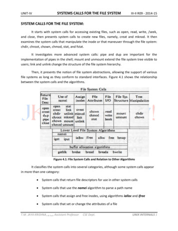
C H A P T E R4Understanding the FlowCollector Data FileFormatThis chapter tells you how to interpret the data collected and saved in FlowCollector data files. Thechapter includes information on the following topics: Data File Directory Structure, page 4-1 Data Filenames, page 4-2 Data File Format, page 4-3 Using the filesready File to Track Data Files, page 4-8.Data File Directory StructureOnce you start FlowCollector, it begins to collect data based on your aggregation schemes and stores thecollected data in data files.If you specified a custom data file directory path as the DataSetPath attribute for a thread, the data filesare stored in the directory you specified. Otherwise, FlowCollector uses the default path, which is/opt/CSCOnfc/Data, and the default data file directory structure shown in Figure 4-1.Figure 4-1Default Data File Directory Structure/opt/CSCOnfc/Data/ Thread ID date Export device aggregationscheme aggregationscheme Export device S6444 Export device.hhmm NetFlow FlowCollector Installation and User’s GuideOL-2587-014-1
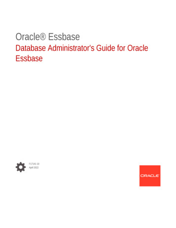
Chapter 4Understanding the FlowCollector Data File FormatData FilenamesStarting with the root directory specified in the DataSetPath attribute of the thread (Figure 4-2 for anexample), a directory is created that identifies the name of the Thread ID. A directory is created belowthat for each day (for example 1998 05 19). Under the date directory, a subdirectory is created for eachexport device (for example, gw.router) or ROUTER GROUPNAME label, and under the exportdevice, there is a subdirectory for each aggregation scheme (for example, CallRecord or SourcePort).The data files are stored by filename under the aggregation scheme subdirectory.Figure 4-2Data File Directory Structure Example/opt/CSCOnfc/Data/ Thread ID Name1998 05 19gw.routerCallRecordSourcePortbb.switch 12295gw.router.1530gw.router.1545CautionFigure 4-1 and Figure 4-2 show the data file directory structure that is created in FlowCollector 3.6.However, this is not the default data file directory structure that is created after you first installFlowCollector 3.6. The Thread ID directory appears only if you set theNFC20 COMPATIBLE MODE configuration parameter in the nf.resources file to No afterinstalling FlowCollector 3.6.See the “Understanding Installation Modes” section on page 2-2 for information about the defaultinstallation process, and see the “Modifying FlowCollector Resources” section on page 5-30 forinformation on how to reconfigure FlowCollector to obtain full FlowCollector 3.6 functionality.For information on how filenames are formed, see the next section, Data Filenames.Data FilenamesThe name given to a data file takes either a long form ( export-resource-name yyyy mm dd.hhmm )or a short form ( export-resource-name.hhmm ), depending on the setting specified for theLONG OUTPUTFILE SUFFIX configuration parameter in the nf.resources file.NoteThe short form of the name is the default file name. To use the long form, you must edit thenf.resources file and set the LONG OUTPUTFILE SUFFIX configuration parameter to Yes. Formore information, see Table 5-6 on page 5-30.Table 4-1 describes the fields of the data filename format.NetFlow FlowCollector Installation and User’s GuideOL-2587-014-2
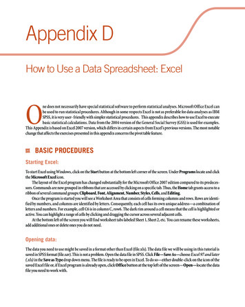
Chapter 4Understanding the FlowCollector Data File FormatData File FormatTable 4-1Data Filename Format Fields and DescriptionsFieldDescriptionexport-resource-name If this export device is named in the ROUTER GROUPNAME configuration parameter, this valueis the label defined by the ROUTER GROUPNAME parameter; otherwise, the domain namesystem (DNS) name of the export device is the source of the data. If the DNS name is not available,the IP address of the export device is used.For information on the ROUTER GROUPNAME configuration parameter, see the “Mapping a Listof IP Addresses to One IP Address or Label” section on page 5-36.hhmmTime when the file was created in hours and minutes (local or Greenwich Mean Time [GMT]).FlowCollector uses GMT as the default time zone.yyyy mm ddDate in year, month, and day format.The following are examples of short and long data filenames:gw-router.1530gw-router 1996 03 15.1530Data File FormatThe format of the data file consists of the data file header and one or more aggregation definition datarecords. The AGGREGATION DEFINITION section interprets the key and value fields in the datarecord area. With this information, data file users can determine the aggregation scheme used by parsingAGGREGATION DEFINITION. The true order of the key and value fields is represented in the datafile. The example in Figure 4-3 shows an abbreviated CallRecord data file.Figure 4-3HeaderSOURCE 172.23.3.167 FORMAT 2 AGGREGATION CallRecord PERIOD 15 STARTTIME 893780360 ENDTIME 893781260 FLOWS 106 MISSED 0 RECORDS 102AGGREGATION DEFINITIONsrcaddr dstaddr srcport dstport prot tos pkts octets flows starttime endtime activetime101.100.100.1 201.0.31.1 11032 53 17 0 3 138 1 893780795 893780795 0101.100.100.1 201.0.32.1 11032 53 17 0 3 138 1 893780795 893780795 0101.100.100.1 201.0.33.1 11032 53 17 0 3 138 1 893780795 893780795 0.101.100.100.1 201.0.27.1 11032 53 17 0 3 138 1 893780795 893780795 012649Data recordsAbbreviated CallRecord Data FileCautionFigure 4-3 shows an example of a FORMAT 2 abbreviated data file created in FlowCollector 3.6.However, this is not the default data file format that is created after you first install FlowCollector3.6. The FORMAT A data file type is created by default. This format does not include theAGGREGATION DEFINITION section. This section appears only if you set theNFC20 COMPATIBLE MODE configuration parameter in the nf.resources file to No afterinstalling FlowCollector 3.6.NetFlow FlowCollector Installation and User’s Guide4-3OL-2587-01
Chapter 4Understanding the FlowCollector Data File FormatData File FormatSee the “Understanding Installation Modes” section on page 2-2 for information about the defaultinstallation process, and see the “Modifying FlowCollector Resources” section on page 5-30 forinformation on how to reconfigure FlowCollector to obtain full FlowCollector 3.6 functionality.Data File DescriptionsFlowCollector data files are made up of two sections: Data File Header Section Format Aggregation Definition Format.Data File Header Section FormatThe data file header section consists of nine field-pairs, each made up of a keyword (all caps) and itscorresponding value (italic) located to the right of the keyword. See Table 4-2 for descriptions of thefields in the data file header section.SOURCE source FORMAT format AGGREGATION aggregation PERIOD period STARTTIME time ENDTIME time FLOWS flows MISSED missed RECORDS recordsNoteTable 4-2Keywords and their value pairs are separated by either a vertical bar ( ) or a comma (,). You canchoose between a vertical bar or comma by using the CSV FORMAT parameter in the nf.resourcesfile.Data File Header Keywords and DescriptionsKeywordDescriptionSOURCEThe label that identifies the source of the NetFlow export traffic summarized in this data file. The labelcan be the IP address, in dotted decimal format, or an ASCII name. If you are using theROUTER GROUPNAME feature, the label is the group name specified in theROUTER GROUPNAME configuration parameter.FORMATA tag to track the version of the data file generated by FlowCollector. FlowCollector 2.0 uses tag A.FlowCollector 3.6 uses tag 2.AGGREGATION The name of a valid, predefined aggregation scheme used to create this data file. See the “AggregationSchemes” section on page 5-11 for more information.PERIODData collection period, specified in minutes. Under some circumstances, FlowCollector might generatea data file before the current data collection period expires. In such a case, FlowCollector adds thekeyword PARTIAL to the filename, and the PERIOD field in the header is identified as PERIODPARTIAL. For more information on partial data files, see the “Partial Data Files” section on page 4-7.STARTTIMEThe time in Coordinated Universal Time (UTC) seconds when this data collection period began.ENDTIMEThe time in UTC seconds when this data collection period ended.FLOWSThe total number of NetFlow export records that are aggregated in this data file.NetFlow FlowCollector Installation and User’s GuideOL-2587-014-4
Chapter 4Understanding the FlowCollector Data File FormatData File FormatTable 4-2Data File Header Keywords and Descriptions (continued)KeywordDescriptionMISSEDThe number of flow records that FlowCollector should have received but did not. The MISSED valueis derived from the sequence numbers (where present) in each packet.If the only data aggregated into a data file is from a V1 NetFlow export datagram or a V7 NetFlowexport datagram with shortcut mode turned on, the MISSED field in the header contains -1 as the value.If any data is aggregated from datagrams in which sequence numbers are available (V5 or V7 withoutshortcut mode), the MISSED field in the header contains the actual count of missed flow records, evenwhen there is a mix of V1, V5, or V7 NetFlow export datagrams.RECORDSThe count of the aggregation records present in this data file.See Figure 4-3 for an example of a typical data file that includes both the header and aggregationdefinition data records. A file that describes the aggregation definitions is located at NFC DIR/include/NFC Aggregation.h.Aggregation Definition FormatThe body of a data file consists of one or more aggregation definition data records. Each aggregationdefinition consists of a keyword portion-one or more key fields-and a value portion-one or more valuefields. For example, in the aggregation definition for the CallRecord aggregation scheme, the keywordportion is the first six fields and consists of the following aggregation scheme keywords:srcaddr dstaddr srcport dstport prot tosThe value portion is the last six fields and consists of the following aggregation values:pkts octets flows starttime endtime activetimeSee Table 4-3 for descriptions of aggregation definition keywords, and Table 4-4 for descriptions ofaggregation definition values. See Figure 4-3 for an example of a typical data file that includes both theheader and aggregation definition data records.NoteIn the aggregation definition, as in the header, keywords and their value pairs are separated by eithera vertical bar ( ) or a comma (,). You can choose between a vertical bar or comma by using theCSV FORMAT parameter in the nf.resources file. Depending on the aggregation scheme youselect, the aggregation definition data record contains a different combination of fields than thatshown in the CallRecord data record example.Table 4-3Data File Aggregations Definition Keyword DescriptionsKeywordDescriptionsrcaddrSource IP addressdstaddrDestination IP addresssrc subnetSource subnetdst subnetDestination subnetsrc maskSource subnet maskdst maskDestination subnet maskNetFlow FlowCollector Installation and User’s Guide4-5OL-2587-01
Chapter 4Understanding the FlowCollector Data File FormatData File FormatTable 4-3Data File Aggregations Definition Keyword Descriptions (continued)KeywordDescriptionsrc user subnetSource user subnet.dst user subnetDestination user subnet.src asSource autonomous system.dst asDestination autonomous system.srcportSource port.dstportDestination port.protProtocol field.protocolProtocol (srcport, dstport, and prot lookup).inputInput interface.outputOutput interface.tosType of service.nexthopNext hop IP address.Table 4-4Data File Aggregation Definition Value sflowsFlow countstarttimeFirst flow stamp (UTC sec.)endtimeLast flow stamp (UTC sec.)activetimeTotal active time (ms)Data File ExampleThe following data file example of the CallRecord aggregation scheme shows the data file header andthe first two aggregation definition data records.SOURCE 192.1.134.7 FORMAT 2 AGGREGATION CallRecord PERIOD 15 STARTTIME 881972378 ENDTIME 881973278 FLOWS 59709 MISSED 0 RECORDS 2345AGGREGATION DEFINITIONsrcaddr dstaddr srcport dstport prot tos pkts octets flows starttime endtime activetime171.69.1.17 172.23.34.36 2963 6000 6 114 2 176 1 768550628 768550628 0171.69.1.23 171.69.25.133 2972 6500 17 0 3 172 1 768520516 768520520 4135.In the CallRecord aggregation scheme, the key portion of the data record is the first six fields andconsists of the following aggregation fields:srcaddr dstaddr srcport dstport prot tosNetFlow FlowCollector Installation and User’s GuideOL-2587-014-6
Chapter 4Understanding the FlowCollector Data File FormatData File FormatFor example, the first six fields in the second data record from the example above are:171.69.1.23 171.69.25.133 2972 6500 17 0where the fields are described as follows:FieldDescription171.69.1.23Source IP address (srcaddr).171.69.25.133Destination IP address (dstaddr).2972Source port (srcport).6500Destination port (dstport).17Protocol byte (prot).0Type of service (ToS).The value portion is the last six fields and consists of the following aggregation values:pkts octets flows starttime endtime activetimeFor example, the last six fields in the second data record from the example above are:3 172 1 768520516 768520520 4135where the fields are described as follows:NoteFieldDescription3Packet count.172Octet count.1Flow count.768520516Time in UTC seconds of the first packet that is summarized in this record.768520520Time in UTC seconds of the last packet that is summarized in this record.4135Active time, in milliseconds; defined as the sum of individual active timecalculations for all the flows summarized into the current record.The activetime value can be 0 if one single-packet flow produces this record. In this case, the valueof the flows field is 1, and the values for starttime and endtime are identical.Partial Data FilesUnder normal circumstances, FlowCollector generates a data file every n minutes, as specified by thePeriod attribute in the thread definition (see the “Creating a Thread” section on page 5-8). For example,if the Period attribute in a thread is set to 10 minutes, FlowCollector collects data for 10 minutes, writesthat data into a data file, and then starts over in a new data collection period.NetFlow FlowCollector Installation and User’s Guide4-7OL-2587-01
Chapter 4Understanding the FlowCollector Data File FormatUsing the filesready File to Track Data FilesUnder certain circumstances, FlowCollector might be forced to generate a data file before the currentdata collection period expires. Such a data file is called a partial data file (because it does not representdata collected for the entire defined collection period) and occurs for one of these reasons: FlowCollector is stopped FlowCollector detects that one of its counters is about to wrap The NFUI is used to modify a thread definition.The data in a partial data file is valid data; the file just does not represent a full data collection periodand is differentiated to prevent data statistics from being distorted by comparing data from full andpartial periods.If FlowCollector has data in its internal aggregation buffers when one of the preceding conditions occurs,it writes the data into one or more data files. Because the current data collection period has not expired,FlowCollector generates and marks the data files differently: the keyword PARTIAL is added to the datafilename as a suffix, and the PERIOD field in the header is identified as PERIOD PARTIAL.In the following two data file examples, the first example shows a complete data file, and the secondexample shows a partial data file (using a different aggregation scheme).SOURCE gw.router FORMAT 2 AGGREGATION Protocol PERIOD 10 STARTTIME 923416099 ENDTIME 923416699 FLOWS 2868330 MISSED 154590 RECORDS 1AGGREGATION DEFINITION protocol pkts octets flowsICMP 2868330 2868330 2868330SOURCE gw.router FORMAT 2 AGGREGATION DestPort PERIOD PARTIAL STARTTIME 923419273 ENDTIME 923419607 FLOWS 4467930 MISSED 0 RECORDS 250AGGREGATION DEFINITION dstport pkts octets flows1 17872 2626340864 178722 17872 2626340864 17872.Using the filesready File to Track Data FilesFlowCollector periodically appends the absolute path names of data files that it has generated to a list ina log file named filesready. FlowCollector identifies the file with the time stamp YYYY MM DD, whereYYYY MM DD represents the year, month, and day. The filesready file is located with the other log filesin the NFC DIR/logs directory. There is one such file per DataSetPath setting, per day.Typically, a client application reads this file every n minutes, processes it to determine the names of anynewly added data files, and then retrieves those new data files.After it finishes writing a new data file, FlowCollector appends the absolute path name of the new datafile onto the list in the filesready file. If FlowCollector deletes some data files as instructed by theFileRetain setting in its thread definitions, it updates the corresponding filesready file. The filesreadyfile contains a header that indicates the format version in use. The following example shows the header,contents, and organization of a typical filesready file.NoteThe following example is from FlowCollector 3.6. However, this is not the default format that iscreated after you first install FlowCollector 3.6. If you are running in NFC 2.0-compatible mode, theoutput begins with data and does not include the format header. The FORMAT 1 identifier lineappears only if you set the NFC20 COMPATIBLE MODE configuration parameter in thenf.resources file to No after installing FlowCollector 3.6.NetFlow FlowCollector Installation and User’s GuideOL-2587-014-8
Chapter 4Understanding the FlowCollector Data File FormatUsing the filesready File to Track Data FilesSee the “Understanding Installation Modes” section on page 2-2 for information about the defaultinstallation process, and see the “Modifying FlowCollector Resources” section on page 5-30 forinformation on how to reconfigure FlowCollector to obtain full FlowCollector 3.6 functionality.FORMAT 1/opt/CSCOnfc/Data/1998 02 Onfc/Data/1998 02 pt/CSCOnfc/Data/1998 02 Onfc/Data/1998 02 pt/CSCOnfc/Data/1998 02 Onfc/Data/1998 02 pt/CSCOnfc/Data/1998 02 Onfc/Data/1998 02 pt/CSCOnfc/Data/1998 02 11/171.71.34.79/Protocol/171.71.34.79.2139NetFlow FlowCollector Installation and User’s Guide4-9OL-2587-01
However, this is not the default data file format that is created after you first install FlowCollector 3.6. The FORMAT A data file type is created by default. This format does not include the . If the only data aggregated into a data file is from a V1 NetFlow export datagram or a V7 NetFlow export datagram with shortcut mode turned on, the .