Transcription
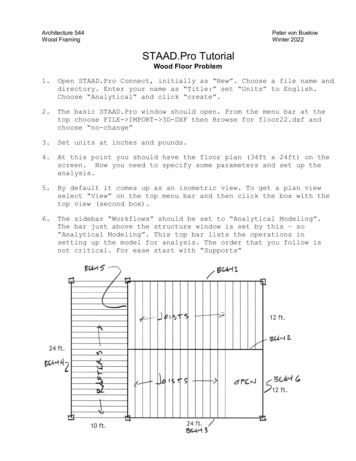
Architecture 544Wood FramingPeter von BuelowWinter 2022STAAD.Pro TutorialWood Floor Problem1.Open STAAD.Pro Connect, initially as “New”. Choose a file name anddirectory. Enter your name as “Title:” set “Units” to English.Choose “Analytical” and click “create”.2.The basic STAAD.Pro window should open. From the menu bar at thetop choose FILE- IMPORT- 3D-DXF then Browse for floor22.dxf andchoose “no-change”3.Set units at inches and pounds.4.At this point you should have the floor plan (34ft x 24ft) on thescreen. Now you need to specify some parameters and set up theanalysis.5.By default it comes up as an isometric view. To get a plan viewselect “View” on the top menu bar and then click the box with thetop view (second box).6.The sidebar “Workflows” should be set to “Analytical Modeling”.The bar just above the structure window is set by this – so“Analytical Modeling”. This top bar lists the operations insetting up the model for analysis. The order that you follow isnot critical. For ease start with “Supports”
7.You need to put supports where the columns are, but like with beamend reactions, to avoid binding, one should be pinned and theothers on partial rollers.8.Pick CREATE - PINNED - ADD9.This should create “support 2” on the menu.Pick that.10. Pick the lower left corner (on B4) and ASSIGN TO SELECTED NODES.Then ASSIGN and YES to proceed.11. Now you should picture the floor plan held at this point andshrinking a bit in scale. B4 will come straight down toward thepinned corner, so the roller is in the Z direction.12. CREATE this support as FIXED BUT and release FZ. The moments getreleased later, on the ends of the beams directly. Click “Add”.13. Select this support and ASSIGN it to the upper end of B414. In the x direction there are 2 more columns.able to slide in the x direction.They both need to be15. CREATE another FIXED BUT support and release FX.16. ASSIGN this support to the two supports on B3. Hold CTRL to selectmore than one at a time, then “Assign”.17. CREATE fifth FIXED BUT support and release FX and FZ.18. Select this last support and ASSIGN it to the remaining twosupports on B1.19. Next we want to supply information about the members. It is a loteasier to deal with members (beams) if they are collected intonamed groups. So first, create some groups.20. From the top bar pic “Utilities” then click “Groups”. Make eightgroups named as n each case start by entering the name in the box and choosing“beam”. Then select those members with member cursor (right clickfor the courser select - beam) Use convenient view, zoom, ctrl topick several, box crossing to select multiple or type the numberif you need to add one, then ASSOCIATE. Use “create” to make the
next group. You can check by picking a Group and then Highlight.After you create all 8 close the window.21. The next tab is Specifications. Choose that, then pick BEAM.What needs to be set here are the END RELEASES. Initially all thebeams are created with fixed ends. In wood construction pinnedends are closer to the build condition, so end releases need to beset. The releases are specified by “local” axis. X is thelength, z is perpendicular in the horizontal plane and y isvertical. The rafters and joists are single members and will geta release at each end(Mz, My). The beams had to be cut intoseveral members in order to join with rafters and joists and willonly get releases where they connect to other beams or columns.22. First create the releases for the joists and rafters:Select the tab “Specifications” and then from right menu Choose:BEAM - RELEASE pick location (first do start then do end) and pickMY MZ. Then “Add”. Add both Start and End.23. To assign, use the groups by SELECT- BY GROUP NAME then pickrafters and joists. Then in the Specification menu, “Assign toSelected Beams”. Do this for both “START My MZ” and “END MY MZ”.24. In this way create a specification for MY MZ release for START andanother for END. One or the other of these two get assigned tothe ends of all the beams. If you hold the cursor over the endsection of a beam, color will indicate green for start and bluefor end. Each member has a start and an end, but it seems more orless randomly assigned (was actually set in AutoCAD).25. Next choose the “Properties” tab. Here you set both the sectiondimensions and wood type and grade. The beams can be designed asGlulam sections while the smaller joists and rafters will bedimensioned lumber. To access the size table pick “SECTIONDATABASE” and “TIMBER”.26. For the Beams 1-6 choose GLT-24F-V4 DF/DF. Then pick (guess)dimensions b and d (YD and ZD) for the beam. Use the standarddimensions from Table 1C in the NDS. The analysis will tell youwhether your guess was safe or not, but at first just guess. (youmight look up a simple span table for glulam or try d in inches 0.9 x span in feet, a bit more or less depending on load andbracing) Initially you might make all the beams the same size orseveral the same size. Use the UTILITIES-GROUP as before toASSIGN the properties to each of the beams.27. Now choose a size for the rafters and joists. Try Hem-Fir:HMFR SS 2X10. If this fails choose larger or if not try smaller.28. MATERIAL has already been assigned with the wood PROPERTY tab.You can check by selecting the MATERIAL tab.
29. At this point check that units are set to feet and pounds: the topbar menu “Geometry” under Structure Input Units is the lower righticon. Open it and click foot and pounds.30. Now set the loads. Pick the “Loading” tab. Pick LOAD CASEDETAILS and ADD. Then set load type(e.g. dead). ADD a load casefor each load type you will use: DEAD use given DL (on joists andrafters) selfweight to include members, and the given LIVE (forjoists), and ROOF-LIVE (for rafters). So 5 load cases includingselfload. Use loads given in the assignment sheet. Add to theload title so you know which load is what. Work through one loadat a time: pick NEW and add the load case. Pick ADD and add theload. Use “Area Load” for all the surface loads and assign themto groups (either RAFTER or JOIST) Don't forget the Negative fordownward in global Y. Alternately you can use the “One-way”command to do the same thing.31. Once all of the Primary load cases are created, you need to makethe combinations. With Load Case Details selected choose NEW- LOADCASE- COMBINATIONS. Then make 1 load case combination for allloads:1. Self DL roof LL roof DL floor LL floor(normally you might have other combinations, but this one will do)32. This is enough information (at last) to perform the analysis.Choose “Analysis” from the top bar and then select “DefineCommands ”. Then use the tab “Perform Analysis” and check “All”.Click Add. Then close.33. Now from the top-top bar choose “Analysis and Design”, and “RunAnalysis”.34. A window should appear (STAAD Output Viewer) and when it runs youshould get 0 Errors, Maybe a Warning (about Area load beingdiscontinued) or a Note. Select View Output File to read these.Then close and go to Post Processing.35. Initially make sure your model was correct. Check some graphicoutput (deflection, moment, shear, etc.) to make sure things arereasonable – e.g. no negative moments.36. On the Workflows left sidebar select “Postprocessing”. Change theview to Isometric, check deflections (they should be downward).Right click and select “Structure Diagrams”. Set scales to bevisible. Check moments to be sure end releases are properly set(no negative moments).37. Once the model is correct you can add a code check for pass/failby the AITC Timber Code. Under the Workflows sidebar return to“Analytical Modeling” and “Design” from the top bar. On the toptop menu select “Analysis and Design”. Under the material scrolldown to Timber and select it. Select from the side bar tabs DESIGNand them TIMBER. At the top of the window on the right pick AITC1994. (it should come up by default)
38. SELECT PARAMETERS: it is better just to pick the ones you areplanning to use because the output is then easier to read. Youshould use:BEAM 1CFB Size Factor for bending (for joists and rafters)CR Repetitive Member Factor (for joists and rafters)CV Volume Factor (for Glulam)CDT (Load Duration Factor) 1.25 on roof1.0 on floorLUZ(bracing against LTB) use ½ joist or rafter length39. DEFINE PARAMETERS: here you put numbers to the above. Some applyto different groups so some need to be set differently fordifferent groups. CD and Luz are different for rafters and joists.There is a little Excel sheet on our website to calculate CV forthe glulams.40. COMMANDS: here add code check. That will do a check and showPass/Fail.41. Now run the analysis again. “Analysis and Design”, and “RunAnalysis”.It will run in another window and give an error report.42. Once again if there are any errors, those need to be fixed. Somewarnings indicate a mistake in the model (like wrong units thatproduce strange values) other warnings are not important(occasional mathematical instability errors that STAAD correctswith springs). For example, the Area Load command is ok for thisfloor system. STAAD is also sometimes entering E in ksi for somereason which you can correct manually if it gives you that warningby adding 000 to the values for E.43. The "output viewer" will show you the .ANL file with a side bar onleft for navigation. Now go to results and see what fails andcheck ratios. “find” “fail”. For dimensioned lumber there is noautomatic member selection, so you will need to look at what failsand the ratio for passing members and adjust member sizes up ordown. The goal is to get the ratio under 1.0 but above 0.7 or0.8. But at the same time you may want to limit the number ofdifferent sizes.44. For the glulam look to the very bottom of the list and you shouldsee the members it “selects”. You have to manually reenter thosesizes into your model and assign them to the appropriate glulams.45. After changing the sizes you need to run the analysis (and select)again because the DL changes and that will change stress. Wheneverything passes and not too overdesigned (check ratio or comparefbz to Fbz)you are finished.46. Post-analysis can give you some informative graphics. Deflectionand Mz are the most helpful. Right-click and pick STRUCTUREDIAGRAMS to see several possibilities. You will need to SCALE thediagrams so you can see them. Animation is also possible.
47. You can capture the images you need with the CAMERA (underUtilities) and build the report (last option underPostprocessing). Images can include: Deflection, Bending z,Shear y, Full 3D Sections (to show member sizes). See assignmentfor list or the posted example. Utilization Ratio plot is notworking for 1984.48. Under Postprocessing tab there is a graphic version of the reportgenerator. It will bring up a menu bar on the right. With thereport setup you can choose what to add to the report. DON'T GETCARRIED AWAY. Some of the output that lists values for each nodeor member can be very detailed and not really what you want for anoverview. You can try these categories: Job Info, Material,Supports, Primary Load Cases, Combination Load Cases, NodeDisplacement Summary, Beam Displacement Summary, Beam Force DetailSummary, Utilization Ratio Table, and the pictures (use list fromassignment). This should be about 10-15 pages max. You canexport it to Word and then remove useless table columns (ones thatare blank or all zero) to make them fit better on LTR paper. Editthe “job information” at the top to include your names and title.
STAAD.Pro Tutorial . Wood Floor Problem . 1. Open STAAD.Pro Connect, initially as "New". Choose a file name and . Choose "Analytical" and click "create". 2. The basic STAAD.Pro window should open. From the menu bar at the top choose FILE- IMPORT- 3D-DXF then Browse for floor22.dxf and choose "no-change" 3. Set units at inches .