Transcription
Cherokee Metropolitan District Water and WastewaterInfrastructure Construction StandardsExceptions to Colorado Springs Utilities Water and Wastewater Line Extension andService StandardsEffective October 29th, 2021i
PurposeCherokee Metropolitan District has partially adopted the Colorado Springs Utilities 2019Line Extension and Service Standards for water and wastewater to standardize additions to itswater and wastewater system. The District maintains a list of exceptions to these standards whichsupersede the Colorado Springs Standards in any conflict. This set of exceptions may besupplemented or modified from time to time without advance notice. This set of exceptions maybe revised following any changes to the Colorado Springs Utilities Standards.Table of ContentsWater ExceptionsPage NumberSection 2. 1Section 3. 2Section 4. 3Section 5. 3Section 6. 4Section 7. 4Section 8. 4Wastewater ExceptionsPage NumberSection 2. 6Section 3. 6Section 4. 7Section 5. 7Section 6. 8Section 7. 8Section 8. 8Detail DrawingsB1-7 Typical Installation for ¾” Through 1” Meters Inside Single Family Residential HDPEServiceB1-9 Typical Installation for ¾” Through 2” Meters Inside Non-Single-Family ResidentialConnection HDPE ServiceB-11A Typical Installation for 1-1/2” Through 6” Meters Inside BuildingW-38 Typical Service Locations Relative to Street Layoutii
Water Standards ExceptionsSection 22.2.A: While in general Cherokee Metropolitan District (CMD) commitments follow a “firstcome, first serve” policy, larger commitments may take more time to review based upon size,amount of information provided by the Developer, or previous commitments made to the site.2.2.B: The development plan is approved by El Paso County instead of the City of ColoradoSprings.2.2.C.1: Cost recovery agreements will be evaluated on a case by case basis.2.2.C.3: Oversized lines may be required for certain portions of the District’s service area andcost recovery agreements will be evaluated on a case by case basis for these locations.2.2.C.5: It is not anticipated that a new aboveground storage facility will be necessary for furtherdevelopments within the District’s main service area. If one is found to be needed to serve theproposed development all costs will be borne by the Developer.2.2.D: CMD will provide a preliminary acceptance letter upon satisfactory completion of finalinspection. After a two year warranty period, during which the Developer must pay the costsassociated with any infrastructure repairs, the District will provide a final letter of acceptance,fully transferring ownership.2.3.D.3: Private hydrants must conform to applicable fire standards (Cimarron, Falcon, orEllicott fire departments).2.5.A: A Hydraulic Grade Line Request Form or similar document is not required. Instead,preliminary plans and proposed uses will be required before plat approval or reapproval in orderto determine overall water use and issue a commitment letter. The Developer will be responsiblefor ensuring adequate fire flows can be provided to the development based on pressures andflowrates available at planned connection points.2.5.B: A CMD approved, developer provided, preliminary utility plan is required to ensure thatproposed connection points are suitable for the development. Contact CMD for nearbyinfrastructure capacity.2.6.D: Connections to CMD water mains will be completed by the Contractor under thesupervision of CMD personnel.2.6.D.2: An outage model will be prepared for all water taps and in the event a large area isanticipated to have interrupted service additional planning and coordination may be needed.2.6.E: Dead end water mains are discouraged in all new development. Dead end mains servingless than 10 homes may be considered on a case-by-case basis.1
2.6.E.7: Looping as determined by CMD and the applicable fire department (Cimarron Hills,Falcon, Ellicott, or others). A looped main may serve both domestic and fire flow subject toDistrict approval.2.6.G.1: These requirements may be modified on a case by case basis.2.6.G.6: Developer shall supply survey drawings and digital location data of abandoned lines.2.6.G.8: All valves shall open left.2.6.G.10: Fire flow modelling in development area shall be conducted by Developer based onpressures and flowrates available at connection points. Fire hydrant placement must be approvedby CMD and the applicable fire agency.2.6.H.8 (d) & (f): Communication about locates should be directed to the Cherokee MetropolitanDistrict front desk.2.6.I: Cathodic protection installation is the responsibility of the Developer with approval byCMD.2.7.D.3: Exceptions to utilities spacing may be made on a case-by-case basis.2.7.E.1: Minimum depth of bury shall be 5 feet and maximum depth of bury shall be 6 feetunless otherwise approved by the District.2.7.K: Consumptive Use Adjustments are not used by CMD. Instead irrigation meters may beinstalled in parallel with the main meter for large water users to accomplish a similar purpose.Section 33.1: Construction plans must be submitted to CMD and may be submitted electronically uponapproval by the District Engineer.3.2.A: All control points must have coordinates supplied in a commonly used geographiccoordinate system such as Colorado State Plane, World Geodetic Survey 1984, or UniversalTransverse Mercator Zone 13. Other coordinate systems may be used subject to approval byCMD District Engineer.3.2.A: All submitted plans and surveys shall be displayed in the North American Datum 1983.3.2B: All listed items are required excepting: Colorado Springs Utilities (CSU) Project Number,Facilities Information Management (FIMS) Map Number, Development Plan Number. Thecounty development number is required in addition to the items listed.3.2.C: All pipeline profiles shall be included. Profiles for service lines to a single end userexceeding 100 feet are required.3.3: Fire flow reports will be prepared by the Developer and reviewed by CMD as well as theapplicable local fire department.2
3.4: Contact CMD for water and wastewater vicinity maps.3.5.A: A Utilities Addressing Plan (UAP) is not required. Lot locations and addresses will beestablished in the billing system upon initiation of service by the first resident.3.5.B: Utilities Design CAD File (UDCF) shall be required during the review process for allprojects for which a new water main is constructed. After final grading of the site an as-builtgeoreferenced UDCF shall be submitted to CMD.3.6: Contact CMD for digital signature blocks.3.6.I: UAP not required.3.6.K: CAD File submittal form not required.Section 44.4.K.1: Potable fire hydrant bodies shall be painted with Rustoleum 7792402 Gloss White.Potable fire hydrant caps and bonnets shall be painted with Rustoleum 7524402 Safety Blue. Ifoil-based paints are unavailable, a reasonable substitute may be used with CMD approval.4.5.A: Copper piping will not be allowed except as in the Meter Assembly4.5.F.6: CMD testing protocol randomly selects meters across all size classes.Section 55.6.A: Inspector overtime is generally not permitted and inspections must occur during regularbusiness hours as defined by CMD at the time of inspection. If a wastewater tie-in or other workthat requires the presence of a CMD Inspector must occur outside of business hours, all overtimeand other costs of the CMD Inspector must be paid by the Developer.5.7.A: Contact the CMD front desk for temporary meters.5.7.C: Customer owned temporary meters are not allowed. Only CMD supplied temporarymeters can be used in the District.5.10.A: Salvaged metal utility pipes shall be delivered to the CMD headworks facility at 6657 EPlatte Ave. Nonmetallic pipes shall be disposed of at the expense of the Contractor.5.12.C: Notifications must be made to the applicable local fire department.5.13.C: A CMD Inspector must be present for filling of pipeline.5.13.D.1: All valves shall open left.5.13.D.4: A CMD Inspector must be present for at first use of temporary blow offs.3
5.20: A CMD Inspector must be present for the collection of bacteriological samples wheneverthis is required.5.20.A: All disinfection testing must be completed by an independent contractor (not CMD orthe Developer) and all costs must be paid by the Developer.5.20.B: Disinfection cost for all lines are paid by the Builder.5.20.C: Contractor shall dispose of chlorinated water as per Colorado Department of PublicHealth and Environment (CDPHE) regulations5.21.B: CMD shall only be responsible for corporation box to curb box repairs if CMD haspreviously fully accepted that infrastructure after the two year warranty period.5.21.O.2: All meters must have an automated meter read system compatible with CMD’ssystem. This system does not use a leader wire.5.21.O.3: Copper is not allowed as a material for the service line from curb box to meter pit.5.22: CMD does not have specific water and sewer line marker decals. The Contractor shoulduse generic markers as specified in 4.6.B.Section 66.5.B.1: Tracer wire at curb stop must run to top of curb stop for access from this location.Section 77: Pump stations will be evaluated on a case-by-case basis.7.2: Should a pump station be determined to be required the Developer will pay all costs ofdesign and construction. Ownership of the pump infrastructure will revert to CMD after a twoyear warranty period.Section 88.2.A: Large-scale agricultural irrigation is currently not allowed using potable or non potableCMD water.8.5.E: Operators of systems receiving non-potable water from CMD must receive training fromCMD, participate in regular meetings with CMD distribution staff, and allow regular inspectionsof the system.8.5.G: Direct discharges of nonpotable water into a waterway, tributary, storm, or sanitary sewerin excess of normal waste must be reported to CMD.4
8.10.C.1: Golf courses do not have additional requirements beyond those imposed on nonpotableusers.8.14.B: Private water wells within the CMD’s boundaries are not allowed.5
Wastewater Standards ExceptionsSection 22.3.D: Cost recovery agreements will be evaluated on a case by case basis.2.3.F: Oversized lines may be required for certain portions of the District’s service area and costrecovery agreements will be evaluated on a case by case basis for these locations.2.3.G: At the conclusion of construction and after successful completion of inspection, CMDwill issue a preliminary letter of acceptance for wastewater infrastructure. At the end of one yearof satisfactory performance, CMD will issue a final letter of acceptance, formally takingownership of the infrastructure.2.5.E.7: Manufacturer-installed plastic steps are required in all manholes.2.7: Pretreatment infrastructure above and beyond CSU standards may be required for anycommercial or industrial development at the discretion of the CMD Pretreatment Coordinator.2.7: Grease interceptors, grease traps, sand/oil separators, or similar pretreatment infrastructureshall have a minimum volume of 1500 gallons.Section 33.1: Construction plans must be submitted to CMD and may be submitted electronically uponapproval by the District Engineer.3.2.A: All control points must have coordinates in a commonly used geographic coordinatesystem such as Colorado State Plane, WGS 1984, or Universal Transverse Mercator Zone 13.Other coordinate systems may be used subject to approval by CMD District Engineer.3.2.A: All elevations shall be referenced to the NAD 1983 Datum.3.2.B: Contact CMD for digital signature blocks.3.2.B: All listed items are required excepting: CSU Project Number, FIMS Map Number,Development Plan Number. The County Development Number is required in addition to theitems listed.3.2.B: If a private main is proposed, clearly indicate this ownership on submitted sheets andindicate the location of the change in ownership from public to private.3.3: Wastewater Master Facility Form (WWMFF) not required, instead provide expected floorspace, dwelling units, occupancy, use, and additional information upon request.3.4: Contact CMD for water and wastewater vicinity maps.6
3.5: UAP is not required.3.5.B: Utilities Design CAD File (UDCF) shall be required during the review process for allprojects for which a new water main is constructed. After final grading of the site an as-built,georeferenced UDCF shall be submitted to CMD.Section 44.2.B.5: Use of steel pipe is not allowed.4.2.H.1: Manufacturer installed plastic steps are required in all manholes.4.4.A: CMD does not have specific water and sewer line marker decals. The Contractor shoulduse generic blue water markers for water lines and generic green sewer markers for sewer lines.Section 55.6.A: Inspector overtime is generally not permitted and inspections must occur during regularbusiness hours as defined by CMD at the time of inspection. If a wastewater tie-in or other workthat requires the presence of a CMD Inspector must occur outside of business hours, all costs ofthe CMD Inspector must be paid by the Developer.5.9.A: Salvaged metal utility pipes shall be delivered to the CMD headworks facility at 6657 EPlatte Ave. Nonmetallic pipes shall be disposed of at the expense of the Contractor.5.9.B: CMD does not have asbestos testing capability. Testing must be done by an outside lab atContractor’s expense.5.12: Manholes shall have a minimum diameter of five feet. This minimum shall be 6 feet incases of four or more pipe penetrations or any pipe larger than 30 inches.5.12: All manholes shall be exterior coated using one of the following options or a Districtapproved equal: Tnemec Series 46H-413 HI - H.B. BUILD TENEME-TAR Epoxy Coal Tarcoating or Tnemec Series 264 with Series 218 primer. All external joints shall be elastomericprotective film wrap; Henry Company Sealants Division, “RUB’R-NEK External Concrete JointWrap”.5.12: Manhole interior coatings conforming to Colorado Springs Utilities Wastewater LESSsection 4.5.A shall be applied to all new manholes.5.25: Manhole adjustments due to paving are the responsibility of the paver unless Cherokee hasissued a final letter of acceptance and the manhole is in a public right of way.7
Section 66.4.A: Plan and profile for all HDPE Sewer Mains, not just those 8 inches or greater must besubmitted as part of the Construction PlansSection 77: Lift stations are not allowed unless specifically approved by CMD.Section 88: Underdrains sharing trenches with other utilities will be reviewed on a case-by-case basis,under no circumstances shall drains connect to wastewater service.8
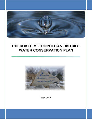
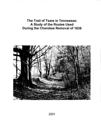
PRESSUREREDUCING VALVE12" MIN.1" X 1 21"UNISTRUT &"L" BRACKETTO FLOORGROUND STRAPNO. 8 GROUNDINGWIRE2 LING6" MIN12" MAXINLETVALVEWATERMETER12" MIN.EXTERNAL WALLCOPPERPIPEINSIDE WALLOUTLETVALVE2 TRUE HOLE CORNERANGLE BRACKET FOR UNISTRUTINLETVALVE8" MIN.OUTLETVALVEPRESSUREREDUCINGVALVEBRASS TAILPIECESWATER METERBASEMENT ORLOWEST LEVELFLOOR DRAIN SHALLBE PLUMBED TO THEFOAMWASTEWATER SYSTEMSLEEVECRAWL SPACE (2XSERVICE DIA).38"X16X2"BOLTSMETERSIZE14"HDPEPREFERRED HORIZONTALMETER INSTALLATIONX 1 41" DRIVENAILANCHORS OR14" X 3" LAGBOLTS INTO2" X 4" BRACING34"SHORT1"METERLENGTHLAYLENGTH W/TAILPIECE7 21"12"10 34"15"NOTES:1.Interim Cherokee Metropolitan DistrictMeter StandardsTORESIDENCEOUTLETVALVE12" CINGVALVEINLETVALVE4' MAX, 3' MINAPPROVEDTRANSITIONCOUPLING6" MIN12" MAXFROMMAINTHE METER SHALL BE PROVIDED AND INSTALLED BY CHEROKEEMETROPOLITAN DISTRICT.2. REFERENCE SECTION 2.7.J (WATER METERS) FOR METER LOOPREQUIREMENTS.3. METERS MUST BE LOCATED ON THE LOWEST FLOOR OF THESTRUCTURE. METERS SHALL NOT BE INSTALLED IN CRAWLSPACES, AREAS ONLY ACCESSIBLE BY LADDER, OR DESIGNATEDSTORAGE AREAS.4. AN APPROVED TRANSITION COUPLING SHALL BE INSTALLED A MINOF 6" AND A MAX OF 12" FROM THE FLOOR. THE METER LOOPSHALL BE CONSTRUCTED OF COPPER, DUCTILE IRON OR STEEL.5. ALL FITTINGS IN THE METER LOOP SHALL BE SOLDERED, FIXEDFLANGED OR THREADED.6. THE METER MUST BE INSTALLED WITH THE CLEARANCEDIMENSIONS AS SHOWN ABOVE. ONE SIDE OF THE METER SHALLBE FREE FROM ANY OBSTRUCTION. 3' MINIMUM CLEARANCE ISREQUIRED ABOVE AND IN FRONT OF THE METER. 24" MINIMUMCLEARANCE IS REQUIRED BETWEEN THE METER LOOP ANDELECTRICAL OUTLETS.7. BRASS INLET AND OUTLET VALVES SHALL BE INSTALLED ON EACHSIDE OF THE METER. INLET AND OUTLET VALVES SHALL BE FULLOPENING, GATE OR BALL VALVES WHICH CLOSE IN DIRECTION OFFLOW. NO CONNECTIONS ARE ALLOWED BETWEEN THE INLETAND OUTLET VALVES.8. A MINIMUM OF 2' OF COPPER IS REQUIRED AFTER THE METERFINAL GRADEEXCEPT WHERE A MANIFOLD (MANIBLOCK) SYSTEM IS USEDDIRECTLY AFTER THE METER AND IS SUPPORTED.9. THE METER SHALL BE SECURED WITH UNISTRUT BEFORE ANDAFTER THE INLET AND OUTLET VALVES AS SHOWN. UNISTRUTSHALL BE ANCHORED TO THE COPPER PIPE.10. GROUNDING IS REQUIRED TO ELIMINATE POTENTIAL FORDISCHARGE OF STATIC ELECTRICITY CAUSED BY FLOW OFWATER THROUGH PIPING. GROUNDING STRAP NOT REQUIRED ONPREFABRICATED LOOPS.FOAMSLEEVEBASEMENT ORLOWEST FLOORFLOOR DRAIN SHALL BEPLUMBED TO THEWASTEWATER SYSTEMCRAWL SPACE (2X SERVICE DIA).FROM MAINTYPICAL INSTALLATION FOR 3/4"THRU 1" METERS INSIDESINGLE-FAMILY-RESIDENTIAL CONNECTIONHDPE SERVICEB1-7DATED 04/2020
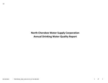
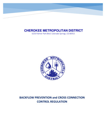
12" MIN.INSIDE WALLDOMESTIC12" MIN.LINE6" MIN.EXTERNAL BRASS TAILPIECESINLET PRESSUREVALVE REDUCINGWATER METERVALVELAY LENGTHW/TAILPIECES7 21"12"1"10 SEMBLY1 21"13-38"SPOOL2"17-38"SPOOLSHORTBRASS TAILPIECESGROUND STRAPCOPPERPIPEAPPROVEDTRANSITIONCOUPLING6" MIN12" MAXPRESSUREREDUCINGVALVENO. 8 GROUNDINGWIRE2 PCUNITSTRUTCUSHIONING CLAMPINLETVALVEWATERMETEROUTLETVALVE2 TRUE HOLE CORNERANGLE BRACKET FOR UNISTRUTBASEMENT ORLOWEST LEVELFINAL GRADEFOAMSLEEVETRACERWIREFROM MAINMETERLENGTHMETERSIZECRAWL SPACERPBACKFLOWPREVENTIONASSEMBLYINLETVALVE1" X 1 21"UNISTRUT38"FLOOR DRAIN SHALLBE PLUMBED TO THEWASTEWATER SYSTEM(2XSERVICE DIA).ANY BRANCHLINES SHALL BEINSTALLEDAFTER THE RPOUTLETDRAIN VALVEPIPING12" MIN AIR GAPX 16X2" BOLTS14"X 1 41" DRIVE NAILANCHORS OR14" X 3" LAG BOLTS INTO2" X 4" BRACINGHDPENOTES:1.2.3.4.5.6.7.8.9.10.11.12.13.THE METER SHALL BE PROVIDED AND INSTALLED BY CHEROKEE METROPOLITAN DISTRICT.REFERENCE SECTION 2.7.J (WATER METERS) FOR METER LOOP REQUIREMENTS.METERS MUST BE LOCATED ON THE LOWEST FLOOR OF THE STRUCTURE. METERS SHALL NOT BE INSTALLED IN CRAWL SPACES, AREASONLY ACCESSIBLE BY LADDER, OR DESIGNATED STORAGE AREAS.AN APPROVED TRANSITION COUPLING SHALL BE INSTALLED A MIN OF 6" AND A MAX OF 12" FROM THE FLOOR. THE METER LOOP SHALL BECONSTRUCTED OF COPPER, DUCTILE IRON OR STEEL.ALL FITTINGS IN THE METER LOOP SHALL BE SOLDERED, FIXED FLANGED OR THREADED.THE METER MUST BE INSTALLED WITH THE CLEARANCE DIMENSIONS AS SHOWN ABOVE. ONE SIDE OF THE METER SHALL BE FREE FROMANY OBSTRUCTION. 3' MINIMUM CLEARANCE IS REQUIRED ABOVE AND IN FRONT OF THE METER. 24" MINIMUM CLEARANCE IS REQUIREDBETWEEN THE METER LOOP AND ELECTRICAL OUTLETS.BRASS INLET AND OUTLET VALVES SHALL BE INSTALLED ON EACH SIDE OF THE METER. INLET AND OUTLET VALVES SHALL BE FULLOPENING, GATE OR BALL VALVES WHICH CLOSE IN DIRECTION OF FLOW. NO CONNECTIONS ARE ALLOWED BETWEEN THE INLET ANDOUTLET VALVES.A MINIMUM OF 5' OF COPPER IS REQUIRED AFTER THE METER EXCEPT WHERE A MANIFOLD (MANIBLOCK) SYSTEM IS USED DIRECTLYAFTER THE METER AND IS SUPPORTED.THE METER SHALL BE SECURED WITH UNISTRUT BEFORE AND AFTER THE INLET AND OUTLET VALVES AS SHOWN. UNISTRUT SHALL BEANCHORED TO THE COPPER PIPE.GROUNDING IS REQUIRED TO ELIMINATE POTENTIAL FOR DISCHARGE OF STATIC ELECTRICITY CAUSED BY FLOW OF WATER THROUGHPIPING. GROUNDING STRAP NOT REQUIRED ON PREFABRICATED LOOPS.GAS FLEX LINE SERVICES SHALL BE LOCATED A MINIMUM OF 18" FROM THE METER LOOP.A BACKFLOW PREVENTION ASSEMBLY IS REQUIRED, IT SHALL BE LOCATED BEFORE THE FIRST BRANCH LINE. FOR BACKFLOWPREVENTION ASSEMBLY REQUIREMENTS, INCLUDING LOCATION, SEE SECTION 2.7.L.THE BACKFLOW PREVENTER SHALL BE SOLDERED OR FIXED FLANGED.TYPICAL INSTALLATION FOR 3/4"THRU 2" METERS INSIDENON-SINGLE-FAMILY-RESIDENTIALCONNECTION HDPE SERVICEB1-9DATED 7/2021
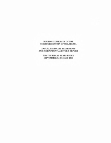
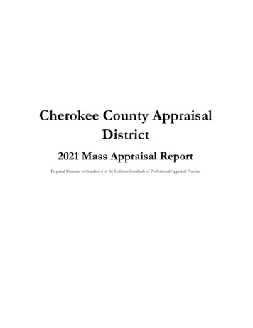
OUTSIDE WALLINSIDE WALLDOMESTICLINE12"PRESSUREINLET REDUCINGVALVEVALVE6" OR 2X's METERDIAMETERWHICHEVER ISLARGEROPTIONALIRRIGATIONLINE18" MIN. FOR3" OR LARGERMETERS12" MIN.OUTLETVALVEOUTLETVALVEINLETVALVEOUTSIDE WALLPRESSUREREDUCING VALVE12"METERSIZEMETER/SPOOLLENGTHCONNECTIONTYPE1 20-38"FLANGED6"24-38"FLANGED18" MIN. FOR3" OR LARGERMETERS12" MIN.INLET PRESSUREVALVE NLET ASSEMBLY OUTLETVALVEVALVE2 PIECEUNITSTRUTCUSHIONING CLAMPINLETVALVEIRRIGATIONLINE TEEOUTLETVALVERPBACKFLOWPREVENTIONASSEMBLYNO. 8GROUNDINGWIREOUTLETWATERVALVEMETER/SPOOL2 TRUE HOLE CORNERANGLE BRACKET FORUNISTRUTRP BACKFLOWPREVENTIONASSEMBLYINLETVALVE1" x 1 21"UNISTRUT38"OUTLETDRAIN VALVEPIPING24" MIN.12" MIN AIR GAPX 16 X 2" BOLTSFINAL GRADEGROUND STRAPCRAWL SPACEFROM MAINFLOOR DRAIN SHALLBE PLUMBED TO THEWASTEWATER SYSTEM(2XSERVICE DIA).14"X 1 41" DRIVE NAILANCHORS OR14" X 3" LAG BOLTS INTO2" X 4" BRACINGHDPE ALLOWED UP TO 2" IN DIAMETER. SEE DETAILDRAWING B1-9 FOR TRANSITION REQUIREMENTS.NOTES:1.2.3.4.THE METER SHALL BE PROVIDED AND INSTALLED BY CHEROKEE METROPOLITAN DISTRICT.METER LENGTHS VARY WITH CERTAIN TYPES OF METER, EXACT DIMENSIONS SHOULD BE OBTAINED FROM CHEROKEE METROPOLITAN DISTRICTREFERENCE SECTION 2.7.J (WATER METERS) FOR METER LOOP REQUIREMENTS.METERS MUST BE LOCATED ON THE LOWEST FLOOR OF THE STRUCTURE. METERS SHALL NOT BE INSTALLED IN CRAWL SPACES, AREAS ONLYACCESSIBLE BY LADDER, OR DESIGNATED STORAGE AREAS.5. THE METER LOOP SHALL BE CONSTRUCTED OF COPPER, DUCTILE IRON OR STEEL.6. ALL FITTINGS IN THE METER LOOP SHALL BE SOLDERED, FIXED FLANGED OR THREADED.7. THE METER MUST BE INSTALLED WITH THE CLEARANCE DIMENSIONS AS SHOWN ABOVE. ONE SIDE OF THE METER SHALL BE FREE FROM ANYOBSTRUCTION. 3' MINIMUM CLEARANCE IS REQUIRED ABOVE AND IN FRONT OF THE METER. 24" MINIMUM CLEARANCE IS REQUIRED BETWEEN THEMETER LOOP AND ELECTRICAL OUTLETS.8. BRASS INLET AND OUTLET VALVES SHALL BE INSTALLED ON EACH SIDE OF THE METER. INLET AND OUTLET VALVES SHALL BE FULL OPENING,GATE OR BALL VALVES WHICH CLOSE IN DIRECTION OF FLOW. NO CONNECTIONS ARE ALLOWED BETWEEN THE INLET AND OUTLET VALVES.6. A MIN. OF 6" IS REQUIRED BETWEEN VALVE AND METER FLANGES, OR 2X's THE DIAMETER OF METER, WHICHEVER IS GREATER.7. A MINIMUM OF 5' OF COPPER IS REQUIRED AFTER THE METER EXCEPT WHERE A MANIFOLD (MANIBLOCK) SYSTEM IS USED DIRECTLY AFTER THEMETER AND IS SUPPORTED.8. BRACING 1 1/2" & 2" METER SHALL BE AS SHOWN. FOR METERS 3" OR GREATER SHALL BE DESIGNED TO ANCHOR METER LOOP AND KEEPSECURED, SUPPORT SHALL BE ATTACHED TO FLOOR.9. GROUNDING IS REQUIRED TO ELIMINATE POTENTIAL FOR DISCHARGE OF STATIC ELECTRICITY CAUSED BY FLOW OF WATER THROUGH PIPING.GROUNDING STRAP NOT REQUIRED ON PREFABRICATED LOOPS.10. GAS FLEX LINE SERVICES SHALL BE LOCATED A MINIMUM OF 18" FROM THE METER LOOP.11. A BACKFLOW PREVENTION ASSEMBLY IS REQUIRED, IT SHALL BE LOCATED BEFORE THE FIRST BRANCH LINE. FOR BACKFLOW PREVENTIONASSEMBLY REQUIREMENTS, INCLUDING LOCATION, SEE SECTION 2.7.L.12. THE BACKFLOW PREVENTER SHALL BE SOLDERED OR FIXED FLANGED.TYPICAL INSTALLATION FOR1-1/2" THRU 6" METERSINSIDE BUILDINGB1-11ADATED 11/2020
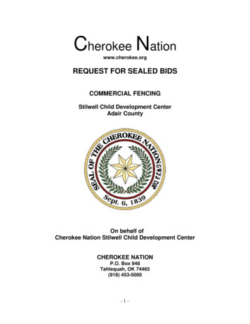
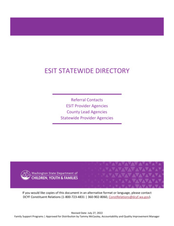
CHEROKEEMETROPOLITANDISTRICTTYPICAL SERVICE LINE LOCATIONSRELATIVE TO STREET LAYOUT
Cherokee Metropolitan District has partially adopted the Colorado Springs Utilities 2019 Line Extension and Service Standards for water and wastewater to standardize additions to its water and wastewater system. The District maintains a list of exceptions to these standards which supersede the Colorado Springs Standards in any conflict.