Transcription
WHITE KNIGHTHEAT PUMPOWNER’S MANUALModels:WK40AWK52AINSTALLATION, OPERATIONMAINTENANCE & SERVICEWHITE KNIGHT HEAT PUMPSBY OXYGEN POOLS7700-B High Ridge Rd. Boynton Beach FL, 33426877-246-9943
WARNING: SAFETY CONSIDERATIONSQualified personnel should perform installation, maintenance and service.Make sure all field wiring conforms to the heater specifications and all national and local codes.Disconnect all power sources before performing any maintenance or service to the heater.INSPECTIONImmediately upon receipt, inspect cartons and their contents for damage due to transit.Damage, if found, should be noted on delivery papers and a claim filed with the carrier. Also,check unit data plate to make sure you have the proper model, before installing.GENERAL INFORMATIONThe information in this manual was prepared to assist in the proper installation, operation,maintenance and service of your new heat pump pool heater. Please read the entire manual andfollow all instructions. Improper installation and use can result in damage to the heater,unsatisfactory operation, and may void the warranty. Retain this manual for quick reference.CAUTION: INSTALLATIONWhen selecting a location consider the following: Heater must be located outdoors. Minimum of 24” of clearance on access / service side of heater. Minimum of 18” of clearance on all three air intake sides of heater. Minimum of 48” of clearance for air discharge (top of unit). The heater should sit on a solid level surface sufficient above grade to prevent water fromentering it from underneath, and allowing condensate to drain from base. The length of water piping and electric should be kept to a minimum to avoid capacityloss and decreased efficiency.LOCATE THE HEAT PUMP AT LEAST 5 FEET FROM POOL WALL ACCORDING TO CODESWATER FLOW & CONNECTIONSWater connections are made at the front or rear of the heater. Water in and out is labeled at the connections.The minimum flow rate is 15 g.p.m. and the maximum flow rate is 50 g.p.m.NOTE: Unions can be used for quick drainage of your heater and winterizing. Heater must be piped downstream from filter in the pool return line.When all the plumbing connections are complete, and ample drying time is allowed, runthe filter pump and check the entire system for water leaks.Make sure filter is clean and there are no obstructions in the filtering system.Proper water flow is essential to the performance of your heat pump.The minimum flow rate is 15 GPM.2
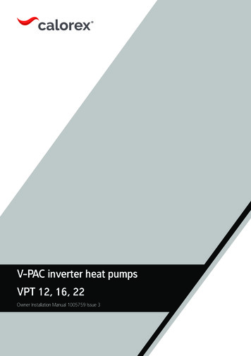
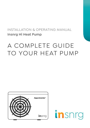
WATERFLOW CONNECTIONSA. TYPICAL INSTALLATIONWHITE KNIGHTHEAT PUMPFROMMAIN DRAIN /SKIMMERRETURNWATER OUTWATER INBALL VALVEFOR FLOW RATESGREATER THAN 50 G.P.M.PUMPCHLORINATOROROZONATORFILTERB. INSTALLATION WITH APOOL AND SPATO P/S ONHEAT PUMPCONTROLWHITE KNIGHTHEAT PUMPFROMMAIN DRAIN /SKIMMERWATER OUTWATER INBALL VALVEFOR FLOW RATESGREATER THAN 50 G.P.M.3 WAYVALVEFILTERPUMPN.O. EXTERNALPRESSURE SWITCHSPA3 WAY VALVECHLORINATOROROZONATORRETURN3
WK40AELECTRICAL CONNECTIONS FOR 110V PLUGDisconnect all power sources before performing any work on unit.Field connections must comply with national and local codes.Plug only into a GFCI protected outletDo NOT use extension cord to extend length of power cordGFCI outlet used for heat pump requires a 20 Amp breakerHEATER MUST BE PERMANENTLY GROUNDED AND BONDED.BONDING WILL DRASTICALLY REDUCE THE CHANCES OF ELECTROLYSIS,“ELECTRICAL CORROSION.”NOTE:THE BONDING LUG IS INSTALLED ON THE BACK OF THE HOUSING(OPPOSITE THE CONTROL PANEL) NEAR THE BOTTOM OF THE CABINET.CONNECT #8 SOLID COPPER BOND WIRE FROM BOND LUG PROVIDEDTO POOL PUMP BONDING TERMINAL ON MOTORWK52AELECTRICAL CONNECTIONS FOR 220V HARDWIREWARNING Field connections must comply with national and local codes,i.e. CSA C22.1 or NFPA70.The work must be done by a qualified electrician. Heater must be permanently grounded and bonded.Bonding will drastically reduce the chances of electrolysis, “Electrical Corrosion.” Use copper conductors only. Disconnect all power sources before performing any work on unit. Standard Power Supply: 230Volts – 60Hertz – 1Phase. See unit data plate for specific ampacity.Wiring Main Power Supply1. Remove the screws from lower left and right side of front cover (service panel).2. Remove the screws on left side of hinged electrical enclosure.3. Route weather tight, flexible conduit through opening at base of unit.4. Connect conduit to bottom of the electrical enclosure using a weather tight fitting. A 1.13” hole is provided near themain contactor to accept a weather tight fitting. Mounting conduit directly to the electrical enclosure will ensure amoisture tight seal, extending the life of the heater.5. Attach grounding conductor to the ground lug provided inside the electrical enclosure (labeled).6. Install L1 and L2 input conductors to the line side of the main contactor. (See wiring diagrams.)7. Connect bond wire (at least #8 solid copper wire) to bond lug provided on right or left side of coil header plate to poolpump bonding terminal or other suitable location.4
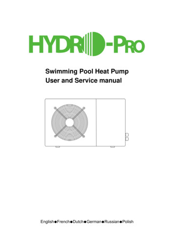
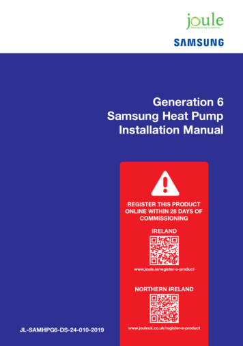
FIELD WIRING DIAGRAM FOR 220V HARDWIRESERVICE DISCONNECTL1 L2CompressorContactorMAINPOWERINGROUNDWiring External Controls and RemotesNOTE: When connecting remotes and external controls to the main control within the electrical enclosure, conduitmust be used within the enclosure to ensure a definite separation of factory wiring/circuits and external control wiring.When installed ensure that there is no transmission of stress to main control wire terminal connections.1. Route conduit through .875” hole provided in bottom of electrical panel.2. Route conduit to the circuit board.3. Connect control wiring to either Pool/Spa or Chiller connection at the bottom right of control board.4. SEE: REMOTE CONTROLS THERMOSTATS AND CONTROLSREMOTE THERMOSTATS AND CONTROLLERS:If a remote thermostat or any other control system is to be used to turn the heater on and off, a normally open drycontact can be made at terminals labeled POOL/SPA on the bottom right of the electronic control board. In the case of aremote thermostat where the temperature will be regulated externally, set the POOL MODE to the OFF position and theSPA MODE to 104º F (40º C). The heater will only run when the remote control calls for heating (circuit closed).To Change Between Pool and Spa set points automatically:This change can be done automatically as the water flow is either directed to the pool or spa.The use of an external water pressure switch in the spa piping IS necessary. A two-wire control circuit must beconnected from the water pressure switch to terminals labeled POOL/SPA on the electronic control board.5
WIRING DIAGRAM FOR 220V HARDWIRE1. Use copper conductors only2. Connect field wiring in grounded rain tight conduit, per rating plate.3. Connect bond wire to pool steel using # 8 solid copper wire or larger.4. All wiring must conform to National (N.E.C.) and local electrical codes.INDICATES FACTORY WIRINGINDICATES FIELD WIRING6
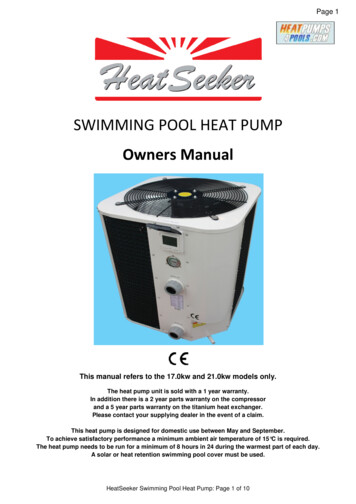
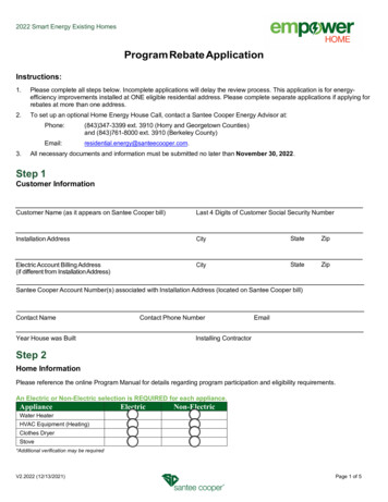
ELECTRONIC CONTROL PANELDIGITAL DISPLAYDISPLAYS WATER TEMPERATURE& CURRENT MODE SETTINGPOOLLED INDICATORSONPOOLINDICATES POOL MODE ENGAGEDONINDICATES COMPRESSOR IS ONSPAINDICATES SPA MODE IS ENGAGEDSPAPOWERSELECT KEYKEY ORKEYSET POOL TEMPDOWNUPSET SPA TEMPDOWNUPSPAPOOLPOOL OR SPA MODESELECT KEYUSED TO CYCLE THROUGHTHE MENU SETTINGSPOWER BUTTONCODESHPS, HP3, FLO - LOW/NO WATER FLOWDEF - DEFROST CYCLEQUICKLY & EASILY TURNTHE UNIT ON & OFFDIRECTIONAL KEYSUSED TO CYCLE THROUGHOPTIONS WITHIN THE MENUWhen the unit is set ON (simply press the power button) the control panel will display the actualPOOL or SPA water temperature for 4 seconds, then the correct mode of operation for 2 seconds.MODE SELECTIONSelecting the desired mode of operation is accomplished by pressing the SELECT KEY.OFF MODEPress the SELECT KEY until you reach OFF. Pressing the UP or DOWN key will allow you toenter either OFF or ON mode. When in OFF Mode the display will show actual water temperaturefor six seconds and then display OFF for two seconds.T EMPERATURE SETPOINT Temperature setpoint maximum for POOL mode is 95 F (35 C). Temperature setpoint maximum for SPA mode is 104 F (40 C).To change the temperature setpoint, press the SELECT KEY until you reach either POOL orSPA. Press either the UP or DOWN key to scroll to your desired temperature setpoint . Onceyour new temperature setpoint has been reached, release the UP or DOWN key. Your newsetpoint will be displayed for five seconds, then revert back to the actual pool or spa watertemperature.SELECTING POOL OR SPA MODEPress the SELECT KEY until you reach P S. Pressing the UP or DOWN key will allow you toenter either POOL or SPA mode. LED indicator lights will verify the mode selected.7
START-UPBefore proceeding with this section make certain all plumbing connections are airtight and leakfree. Flow rates should not exceed 50 GPM maximum. Use of an external bypass is necessary at50 GPM and above. Minimum flow rate is 15 GPM. Turn filter pump time clock to the ON position and set filter pump hours. For initialheating, the pool heater and filter pump may need to run continuously until your desiredtemperature is reached. After initial heating is achieved, the heater will run only tomaintain your desired temperature. Turn power supply to heater ON. The control panel will light up and display either OFF or the actual pool watertemperature. Select POL or SPA and set your desired water temperature by scrolling either up ordown. If your programmed water temperature is above the actual water temperature, the fan andcompressor will start once the time delay is satisfied.NOTE: EACH TIME THE COMPRESSOR TURNS OFF; IT IS PROTECTED BY A 5 MINUTE ANTI-CYCLING DELAY.INITIAL HEATINGINITIAL HEATING MAY REQUIRE YOU TO RUN YOUR HEATER AND FILTER PUMP CONTINUOUSLYUP TO 72 HOURS, OR MORE, DEPENDING ON THE FOLLOWING FACTORS: Temperature difference between actual water temperature and desired water temperature.Size of pool.Ambient air temperature, the cooler the air temperature the longer the heating time.Heat loss (evaporative, convective, radiative and conductive).A pool cover / solar blanket will reduce initial heating time up to 50 percent.NOTE: IT IS NORMAL FOR WATER TO DRIP FROM THE DRAINHOLES AT THE BASE OF THEHEATER. THE UNIT PRODUCES CONDENSATION WHEN IT OPERATES.REDUCING HEAT LOSS - POOL COVER / SOLAR BLANKETWe highly recommend the use of a pool cover / solar blanket. Covering your pool is the single most cost effectivemeans of reducing heat costs up to 70 percent.Evaporation through the pool surface area accounts for about 70 percent of pool heat loss. The beneficial effect ofusing a pool cover or solar blanket can be dramatic, especially early and late in the swimming season.FULL SUN INCREASES EFFICIENCYShading of the pool reduces heater efficiency and will require the heater to run longer. Trimming or eliminatingobstructions that block direct sun onto the pool greatly enhances the performance of any heater.8
DEFROST CYCLEThe heat pump pool heater has automatic defrost. When the outdoor temperature drops below 40 F, frost may start to form on the evaporator coil. Frost buildup will be heaviest on humid dayswhen the temperature is between 35 and 40 F. During the defrost cycle, the display will show“DEF” indicating the unit is defrosting. During this time the compressor is inactiveInternal Protection AnalyzersThe heater is equipped with internal devices to monitor and protect the integrity of the unit. If anabnormal condition occurs, the device will interrupt the operation of the unit and may display theappropriate code on the control panel. LOW WATER FLOW: Indicated by“HP” or “HP3” on the control panel. The heater isdesigned to run efficiently above fifteen (15) GPM. If there is insufficient water flowthe unit will shut down, protecting the compressor. The usual causes for these conditionsare a dirty pool water filter, a restriction in the return line (i.e. skimmer), or impropervalve positioning.NO WATER FLOW: Indicated by“FLO” on the control panel. When the filter pump isoff, or if the water flow to the heater is interrupted during the heating mode, the internalwater pressure switch will shut down the unit. When normal water flow resumes, theheater will automatically restart itself.Other analyzer codes include: “LP”, “tSO”, “tSS”, “ESO” and “ESS”.The TROUBLESHOOTING CHECKLIST on pages 8-9 goes into further detail on these analyzer codesMAINTENANCEWARNING - DISCONNECT ELECTRICAL POWER TO UNIT BEFORE STARTING ANYMAINTENANCE TO PREVENT SERIOUS INJURY FROM SHOCK.Protecting your Heater Keep your pool filter system clean and free of restrictions to ensure proper water flow Check water chemistry regularly. Misuse of chemicals will cause permanent damage toyour heater and other pool equipment. Manufacturers can void warranties for damage asa result of poor water quality. Free airflow is essential. Keep the evaporator coil clean and free of weeds, leaves, glassclippings, dirt and other debris that will decrease the airflow. Keep fences and shrubsaway from air inlets (sides and back of heater). Frequent rinsing of the evaporator with fresh water will remove build up from its surfaceAlways spray the coil gently with a regular garden hose being careful not to bendaluminum fins. Regular cleaning of the cabinet will improve its appearance and extend the life of thefinish.9
WINTERIZINGIt is essential that all water within the unit be properly drained when winterizing your pool equipment.be properly drained. When water freezes, it expands, damaging piping. Turn thermostat settings to OFF. Turn filter pump to OFF. Turn power to unit OFF (i.e. pull disconnect or turn circuit breaker OFF). Disconnect water inlet and outlet unions at the back of the unit. Be careful not to loserubber o-rings. Flush the heater piping out with fresh water to remove any residual chemicals. Use low-pressure air or vacuum to remove water that has accumulated inside the pipingof the heater.TROUBLESHOOTING CHECKLIST Check to see that the electrical power is on. Reset breakers, or replace fuses if necessary.Check to be sure the electric control panel is set properly. The desired temperature mustbe set above the actual pool or spa temperature for the heater to run.Check to make sure the evaporator coil has enough clearance and that there are norestrictions to its airflow.Certain ambient air conditions may cause the heater to go into defrost mode, displayed onthe control panel as “DEF” .NOTE: IT IS NORMAL FOR WATER TO DRIP FROM THE DRAINHOLES AT THE BASE OF THEHEATER. THE UNIT PRODUCES CONDENSATION WHEN IT OPERATES.ANALYZER CODESFAILURE LOCK-OUT: This feature is for the protection of the heater. If the same failureoccurs three (3) times within an hour, the control will not allow the unit to restart. and shalldisplay the appropriate code (i.e. “LP3”, “HP3”).The reset to normal conditions can beaccomplished by pressing any button on the control touch pad one time.“FLO” (Little or No Water Flow)The pump is not running.The filter is dirty or clogged.Shortage of water to pump - air leak.Undersized pump.Valves not in correct position.Filter in backwash mode.Water pressure switch needs adjustment, or is defective.“HPS” (Compressor High Pressure) Low water flow to heater. Defective high-pressure switch.10
ANALYZER CODES (Cont.)“LPS” (Compressor Low Pressure) Evaporator coil dirty. Fan motor not running. Low refrigerant pressure. Defective low-pressure switch. Low ambient air temperature.“ESO” Evaporator temperature sensor connection opened. Check for cut or loose sensor wiringor defective sensor.“tSO” Water temperature sensor connection opened. Check for cut or loose sensor wiring ordefective sensor.“ESS” Evaporator temperature sensor connection shorted. Check for a short in sensor wiring ordefective sensor.“tSS” Water temperature sensor connection shorted. Check for a short in sensor wiring ordefective sensor.“DEF” Heat pump in defrost cycle.CALLING FOR SERVICE Please eliminate any water flow problems before calling for service.If you are unable to contact the installing agent, please contact OXYGEN POOLS, LLCA factory representative will assist you or your serviceman over the phone.877-246-9943SERVICE PERFORMED WITHIN THE WARRANTY PERIOD MUST BE APPROVED BY WHITE KNIGHTPRIOR TO SERVICE BEING PERFORMED AND ONLY BY A WHITE KNIGHT AUTHORIZED TECHNICIAN.SEE WARRANTY FOR DETAILS.Please have the following ready before calling:MODEL #:SERIAL #:DATE OF INSTALLATION:NAME OF OWNER:ADDRESS:CONTACT # :NATURE OF PROBLEM:11
WHITE KNIGHT HEAT PUMPSBY OXYGEN POOLS7700-B High Ridge Rd. Boynton Beach FL, 33426877-246-9943
WHITE KNIGHT HEAT PUMP WHITE KNIGHT HEAT PUMPS BY OXYGEN POOLS 7700-B High Ridge Rd. Boynton Beach FL, 33426 877-246-9943 Models: WK40A WK52A. 2 . CONTROL BALL VALVE FOR FLOW RATES GREATER THAN 50 G.P.M. CHLORINATOR OR OZONATOR 3. 4 Disconnect all power sources before performing any work on unit.