Transcription
0)It)0)I0
UNCLASSIFIEDSECURITY CLASSIFICATION OF THIS PAGEREPORT DOCUMENTATION PAGEla. REPORT SECURITY CLASSIFICATIONForm ApprovedOMB No. 0704-0188lb. RESTRICTIVE MARKINGSUnclassifiedNone2&-SECURITY CLASSIFICATION AUTHORITY3. DISTRIBUTION/AVAILABILITY OF REPORTApproved for public release; distxibution unlimited.2b. DECLASSIFICATION/DOWNGRADING SCHEDULE5. MONITORING ORGANIZATION REPORT NUMBER(S)4. PERFORM!NG ORGANIZATION REPORT NUMBER(S)No. 24666a. NAME OF PERFORMING ORGANIZATION6b. OFFICE SYMBOL7a. NAME OF MONITORING ORGANIZATION)Materials, Fuels and Lubricants Dir(f#llaw&Chemistry Research DivisionSTRBE-VC"6c.ADDRESS (Ciyo State, nd ZIP Code)7b. ADDRESS (City, State, and ZIP Code)Belvoir RD&E CenterFort Belvoir, VA 22060-5606Sa. NAME OF FUNDING/SPONSORINGORGANIZATION"Sc.ADDRESS (City, State, and ZIP Code)8b. OFFICE SYMBOL(if applikable)9. PROCUREMENT INSTRUMENT IDENTIFICATION NUMBER10. SOURCE OF FUNDING NUMBERSPROGRAMELEMENT NO.PROJECTNO.TASKNO.11. TITLE (Incdude Security Classification)Multi-Metallic Galvanic Corrosion (U)12. PERSONAL AUTHOR(S)Lisa R. Whiting. Chris Miller, and Dario A. Emetic13&. TYPE OF REPORT13b. TIME COVERED14. DATE OF REPORT (YeatMondt, Day)FinalFROM .Marf. TO Feb 8B8 May 1988"16.SUPPLEMENTARY NOTATIONWORK UNITACCESSION NO.15. PAGE COUNT1817.18.SUC'JECT TERMS (Continue an reverse if necessary and identify by block number)FIELDGROUP 1 SUB-OUPUPGalvanic corrosion; mechanical properties; composites;lluminunm alloys. (Ut U .iil19. ABSTROT (Continue on reverse if necessary and identfify by block number)-in the past, there have been a number of material failures in the Army's equipment. Many ofthese failures have been caused by some form of corrosion. One type of corrosion involvedis galvanic corrosion. This happens when dissimilar metals come in contact in an electrolyte.The electrolyte could be a marine or even a humid environment. When this occurs, the lessnoble metal (anode) corrodes in order to protect the more noble metal (cathode). Byexposing multi-metallic galvanic couples of high strength materials in aggressiveenvironments, the number of failures in bridges and other military equipment could bereduced.4. \C20, DISTRIBUTION/AVAIIABIUTY OF ABSTRACTf UNCLASSIFIED/UNUMITED[ SAME AS REPORT[] OTIC USERS22L. NAME OF RESPONSIBLE INDIVIDUALLisa RPWhingDD Form 1473, JUN 8621. ABSTRACT SECURITY CLASSIFICATIONUnclassified22b. TELEiPONE (include Area Code) 22c. Office Symbol703-664-1127STRBE-VCPrevious editions are obsolete.SECURITY CLASSIFICATION OF THIS PAGEUNCLASSIFIED
PREFACEIn the past, there have been a number of material failures in the Army'- equipment. Many of thesefailures have been caused by some form of corrosion. One type of corrosion involved is galvaniccorrosion, which occurs when dissimilar metals come in contact in an electrolyte. The electrolytecould be a marine or a humid environment. When this occurs, the less noble metal (anode) corrodesin order to protect the more noble metal (cathode). By exposing multi-metallic galvanic couples ofhigh strength materials in aggressive environments, the number of failures in bridges and othermilitary equipment can be reduced. This technical report presents research performed for thefollowing dual purpose:"* To determine the effect of multi-metallic galvanic reactions on the mechanical properties ofhigh strength materials in aggressive environments, and" To determine the effect of placing a finite space between the three dissimilar metals asopposed to placing them in intimate contact.The galvanic couples are made from various materials being considered for Army equipment. Theyare first exposed to an aggressive environment, and then corrosion rates and mechanical propertiesof each material are determined. From this data, it can be decided if the corrosion that develops iscosmetic, or if it has an effect on the mechanical properties of the material.',T,-iIor, ,-iNiicopy'NSLCi
TABLE OF CONTENTSSECTION ITEST DESCRIPTION ---.----.ASTM Standards .Equipment Used .Procedure .Environment .SECTION IITEST OBSERVATIONSEffects of Spacers .Galvanic Corrosion .SECTION MITEST CONCLUSIONS .APPENDIXCORROSION RATES AND MECHANICALPROPERTIES .o.11114.555. 8A-1FIGURES1 Materials for Testing .2 Galvanic Couples Tested .223Specimen for Galvanic Corrosion Testing .345Corrosion Rates of 6061-T6 .Corrosion Rates of Cathodes .676 Elongation of 6061-T6 .iv8
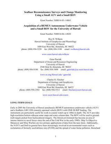
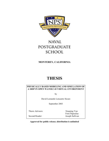
SECTION L. TEST DESCRIPTIONThis section presents American Society for Testing and Materials (ASTM) standards, equipmentused, test procedure, and test environment for this galvanic corrosion research.ASTM STANDARDSASTM proposed standard Gxx, Test Methodfor Galvanic Corrosionin the AtmosphereASTM E8, Tension Testing of Metallic MaterialsASTM G1, Preparing,Cleaning,and Evaluating CorrosionTesting SpecimensASTM G31, LaboratoryImmersion CorrosionTesting of MetalsASTM G44, AlternateImmersion Stress CorrosionTesting in 3.5% Sodium Chloride SolutionASTM G82, Development and Use of a GalvanicSeriesfor PredictingGalvanic CorrosionPerformanceEQUIPMENT USEDTensilkut, floor model, Sieburg Intemational IncorporatedCut off Wheel, Isocut Model, Buehler LimitedImmersion Bath, fabricated by Blair IncorporatedScales, Model #B3000D, OhausBaldwin Tensile Tester, Model #472470, Southwark Division, Tate-Emery CompanyCalipers, Model #120, Starrett CompanyExtensometer, Model #P3M, Satec IncorporatedSaw, Abrasimet Model, Buehler LimitedPROCEDUREThe galvanic testing was performed on materials that were considered for use in equipment beingcurrently developed (Figure 1). The material known as 6061-T6 was combined with other pairs ofmetals, resulting in eleven different combinations (Figure 2). The procedure used was adapted froman ASTM proposed standard Gxx, Test Methodfor Galvanic Corrosionin the Atmosphere, and is asfollows:1. A 4" x 6" panel of one material (6061-T6) was degreased and weighed.2. The panel was then sandwiched between two 1" x 3" panels of two different materials, whichwere also degreased and weighed (Figure 3). The samples were wet assembled using M1L-S-81733polysulfide sealant to avoid any galvanic reaction between the stainless steel bolts and the panels.1
Aluminum Alloys* 5052-H32* 6061-T6* 7075-T73Carbon Steels* 1045* C1117 Cadmium PlatedStainless Steels* 304* 430Brass* 360 1/2 hardComposites"* Graphite Epoxy"* Graphite Epoxy coated with FiberglassFigure 1. Materials for TestingANODE4" x 6" DE A1" x 3" PANELCATHODE B1" x 3" PANEL6061-T6430 SS1045360 ure 2. Galvanic Couples Tested26061-T65052-H32360 BrC1117C1117C1117430SS1045304SSCompositeComposite
u '.IMJ r Lne'-.-,.I w. -- -Ur-' -I - - --b,-- - --- .,.-3.0"71Itg1. .7pec-nditesiletestspecmen2.00"3.4. Inu5. Ipeebot-2pee301. wanodrspae4 pieces6. Isltn washers - 4 pieces8. Insulating sleeve-2 piecesFigure 3. Specimen for Galvanic Corrosion Testing34.0"-
3. Three samples of each combination were then placed in the test environment for a given lengthof time.4. Another set of the same combinations were assembled, this time placing a 0.065" thick teflonspacer between each of the metals.5. After environmental testing of the panels was completed, the panels were photographed,disassembled, and rephotographed in the area under the small panels.6. The panels were chemically cleaned according to ASTM G1, Preparing,Cleaning,andEvaluating CorrosionTest Specimens, and then reweighed. The corrosion rate of each panel wasfound by using the equation:Corrosion Rate (K*W)/(A*T*D)where:K constant (3.45*10A6 for mpy)T time of exposure (hours)A - area (cm 2)W mass loss (grams)D density (g/cm 3 )7. Any change in the mechanical properties was then determined. A subsize 1/4" wide tensilesample with a 1" gage length was cut out of the center of the large panel and tested according toASTM E8, Tension Testing of Metallic Materials. The properties measured were ultimate strength,yield strength, and percent elongation.8. These properties were compared to the baseline to determine any deviation caused by thegalvanic reaction between the materials in the given environment.ENVIRONMENTThe environment chosen for this experiment was selected with the intent of recreating actualconditions that these materials may be exposed to when used in military equipment. The testenvironment was an immersion bath.In this test, the panels were exposed to a 3.5% Sodium Chloride (NaCl) solution, acidified to a pHof 4.1. This pH was chosen to simulate an acid rain environment and the 3.5% NaCl was the mostcorrosive marine solution. Panels were cyclcd in and out of this bath-l0 minutes soaking and 50minutes air drying-for 75 days. The immersion test was run at 35"R4
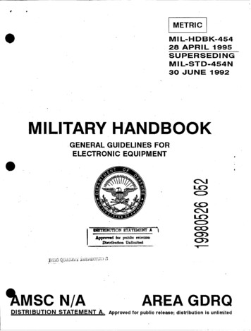
SECTION IL TEST OBSERVATIONSEFFECTS OF SPACERSWhen the set of galvanic couples containing the spacer in between the panels was compared to theset without spacers, the greatest effect was seen in the corrosion rates. Over half of the couples withspacers had a higher corrosion rate than those without the spacer in this acidic marine environment.This was especially true when one of the metals coupled to the 6061-T6 was a plain carbon steel (forexample, 1045). The couples containing stainless steel or graphite carbon epoxy with the 6061-T6were the leaist affected and showed no increase in corrosion rates. The corrosion rates for 6061-T6(anode) are shown in Figure 4 and the Appendix. The corrosion rates for the cathodes are shown inFigure 5 and also in the Appendix. Further studies are needed to determine the reason for thesedifferences.These results were also reflected in the change in elongation of the 6061-T6 when the samples weremechanically tested. Those combinations having high corrosion rates with the spacers showed aloss of elongation (see Figure 6 and the Appendix). This loss of elongation indicated that thematerial was becoming brittle and could result in catastrophic failure. This included the coupleswith 1045 as well as the 6061-T6 control. The samples containing the stainless steels, 304 and 430,had higher or equal percent elongation of the 6061-T6 with the spacer than without.The spacers between the panels had no significant effect on the yield strength (43.1 ksi) or ultimatestrength (47.1 ksi) of the 6061-T6 (see Appendix). These properties remained stable for the606 l-T6 whether or not the couples contained spacers.GALVANIC CORROSIONThe multi-metallic galvanic couples presented different corrosion trends than the bi-metalliccouples. When 1045 was one of the cathodes in combination with any of the other materials, itcaused the highest corrosion rates of the aluminum. This was contrary to the typical Galvanic Seriesin Seawater.* According to the series, the graphite-epoxy composites should have had the greatesteffect on the corrosion rate of 6061-T6. Instead, the corrosion rate of the aluminum with thecomposite was only half of or less than the corrosion rate when 6061-T6 was in any of thecombinations containing 1045. In the case of the 6061-T6 coupled with 1045 and the composite, thecorrosion rate of the 1045 panel more than doubled compared to the other couples containing 6061T6, 1045, and another metal. Although the 1045 was separated from the composite by the 6061 -T6,it acted as an anode, more so than the aluminum. The 430 stainless steel coupled with the C 1117 or7075-T73 showed the smallest deviation from the control (6061 -T6/606 1-T6).The elongation of the 6061-T6 during mechanical testing correlated with the corrosion rates. Thosecouples with high corrosion rates (those containing 1045) showed a decrease from the baseline ofthe percent elongation. The 360 Brass/C1117 coupled to 6061-T6 also had a noticeable decrease inpercent elongation. The remainder of the couples did not exhibit any significant loss of elongation.Neither the yield strength nor the ultimate strength was affected by the galvanic couple in thisenvironment. There were no significant losses of strength for any of the couples. Of those thatsuffered the high corrosion rates, the loss of strength was only a few percent.Failure Analysis & Prevention, Metals Handbook Vol. 10, ASTM 1975, p. 182.5
MPY35-030-/25/20-015-10-es-10"06061-T6 COUPLED WITH: 6061-T6/6061-T67075-T73/430SS43058/;02-1L12MPY35- 3025-20-'15-06061-T6 COUPLED WITH: 360 1045/360 BRASS30 0'25-010-05006061.T6 COUPLED WITH: 1045/1045M1045/304SSWITHOUT SPACER430SS/C1117MwrrH SPACERFigure 4. Corrosion Rates of 6061-T66304SS/C1117
MPY1051045360 1117SwITHoUTSPACERMS&SC11175052-H32wrrH SPACERFigure 5. Corrosion Rates of Cathodes7C1117
Ol 0 BRASS1045/304SS1045/COMPOSITEWITH SPACERWITHOUT SPACER360 BRASS/C11171045/10450BASELINEFigure 6. Elongation of 6061-T6SECTIONm. TEST CONCLUSIONSPlacing a small space between the panels, thus avoiding intimate contact, had an adverse effect onthe corrosion rate which in turn affected the elongation of most material couples.The couples containing steels and brass were the most affected by the spacers, while thosecontaining stainless steel and composite were the least affected.The composite had a larger effect on the corrosion rate of the small 1045 panel than on the 6061-T6panel that was in direct contact with it. Whether this was due to the temperature or pH of thesolution, the size of the panels or the nature of this composite cannot be determined at this time.Electrochemical potential tests are needed to explain some of the galvanic reactions that occurred inthis 35'F environment.8
APPENDIDCORROSION RATES AND MECHANICAL PROPERTIESCORROSION RATES OF IMMERSIONBATH 35 0 F FOR 75 DAYSANODE CATHODE ACATHODE B6061-T61045360 Brass6061-T610456061-T6WITHOUT SPACERAVG MPYANODE CATHODE A CATHODE B ANODEWITH SPACERAVG MPYCATHODE A CATHODE B14.7412.991.1932.4521.371.37304 94.591.076061-T6360 175.300.5827.111.200.5819.476061-r6430 72.010.0019.831.860.3025.796061-T67075-T73430 SS2.4519.580.103.4314.110.40A-1
TENSILE DATA OF 6061-T6IMMERSION UT SPACERGALVANICSTANDARDDEVIATIONAVGWITH SPACERGALVANICSTANDARDAVGDEVIATION% jonp6061-T6/6061-T6Comp-MOb 00.70.20.41.31.31.21.01.50.6ULTIMATE STRENGTH 430SS/0502-H32360BruI/C1117304SS/ .446.142.842.144.944.345.4YIELD STRENGTH 30SS,0502-H3236OBruas/Cl 3.641.742.543.342.840.142.341.642.6A-2
DISTRIBUTION FOR REPORT NO. 2466DEPARTMENT OF DEFENSE1Chemical Research R&D CenterATTN: SMCCR-SPS (Tech Library)Aberdeen Proving Ground, MD 21005Director, Technical InformationDefense Advanced Research ProjectsAgency1400Wilson Blvd.Arlington, VA 222091CommanderUS Army Aberdeen Proving GroundATTN: STEAP-MT-U(GE Branch)Aberdeen Proving Ground, MD 21005DirectorDefense Nuclear AgencyDirectorATrN: TITLUS Army Materiel Systems Analysis AgencyATTN: AMXSY-MPAberdeen Proving Ground, MD 21005-5071Washington, DC 203052CommanderDefense Technical Information CenterCameron StationAITN: DTIC-FDACAlexandria, VA 22304-61451DirectorUS Ballistics Research LaboratoryATTN: AMXBR-OD-ST (STINFO)Aberdeen Proving Ground, MD 21005-50661DirectorUS Army Engineer Waterways ExperimentStationAT N: Chief, Library BranchTechnical Information CenterVicksburg, MS 39180CommanderUS Army Armament Research &DEPARTMENT OF THE ARMYHQDA (DAMA-AOA-M)Washington, DC 20310HQDA (DALO-TSM)Washington, DC 20310HQDA (DAEN-RDL)Washington, DC 203141Development CommandA TN: SMCAR-TSSDover, NJ 07801-5001HQDA (DAEN-MPE-T)Washington, DC 20314CommanderUS Army Missile Research & DevelopmentCommandATITN: AMSMI-PRRedstone Arsenal, AL 35809DirectorArmy Materials and Mechanics ResearchCenterATTN: AMXMR-RL Technical LibraryWatertown, MA 02172-00011CommanderUS Army Troop Support & AviationMateriel Readiness CommandATN: DRSTS-MES (1)4300 Goodfellow Blvd.St. Louis, MO 63120DirectorPetrol & Fld Svc DeptUS Army Quartermaster SchoolFort Lee, VA 23801Distribution-1
US Army Tank Automotive CommandAITN: DRSTA-TSLWarren, MI 48090US Army Laboratory CommandATrN: M. Levy SLCMT-MNMaterials Technology LaboratoryWatertown, MA 02172-0001US Army Laboratory CommandATITN: J. Wells SLCMT-MCZMaterials Technology LaboratoryWatertown, MA 02172-0001CommanderUS Army Electronics Research &Development CommandATTN: DELSD-LFort Monmouth, NJ 07703-5301PresidentUS Army Aviation Test BoardATTN: STEBG-POFort Rucker, AL 363601HQDAODCSLOGDALO-TSERoom 1E588, PentagonWashington, DC 20310-05611Plastics Technical Evaluation CenterARRADCOM, Bldg 3401Dover, NJ 078011CommandantUS Army Engineer SchoolATZA-CDDFort Belvoir, VA 220601US Army AMCCOMATTN: Joseph Menke1032 N. ThornwoodDavenport, IA 528041CommanderHeadquarters, 39th Engineer Bn (Cbt)Fort Devens, MA 014331PresidentUS Army Airborne, Communications &ElectronicsATTN: STEBF-ABTDFort Bragg, NC 283071PresidentUS Army Armor and Engineer BoardATTN: ATZK-AE-PD-EFort Knox, KY 401211Commander and DirectorUSA FESAATTN: FESA-TSFort Belvoir, VA 220601DirectorATTN: STSTO-TPPTobyhanna Army DepotTobyhanna, PA 18466-5097US Army Aviation School LibraryPO Drawer 0Fort Rucker, AL 36360HQ 193D Infantry Brigade (Panama)AITN: AFZU-FEAPO Miami 3400422Special Forces Detachment, EuropeA'TTN: PBOAPO New York 09050Engineer RepresentativeUSA Research & Standardization Group(Europe)Box 65FPO 09510CommanderRock Island ArsenalATTN: SARRI-LPLRock Island, IL 61299-7300Distribution-2
11HQ, USAEUR & Seventh ArmyDeputy Chief of Staff, EngineerATTN: AEAEN-MT-PAPO New York 09403DirectorUS Army TRADOCSystems Analysis ActivityATTN: ATAA-SL (Tech Lib)White
Baldwin Tensile Tester, Model #472470, Southwark Division, Tate-Emery Company Calipers, Model #120, Starrett Company Extensometer, Model #P3M, Satec Incorporated Saw, Abrasimet Model, Buehler Limited PROCEDURE The galvanic testing was performed on materials that were considered f