Transcription
Best Practices11This chapter describes “best practices” for implementing heterogeneous Storage AreaNetworks. The information contained in this chapter should be used as a guide for constructingyour SAN. Although every attempt has been made to provide a best practice recommendation,some aspects of SAN implementation are a matter of preference. Also, the physical location ofservers, storage, computer labs, or specific building layout and location may dictate particularaspects of your SAN implementation. In part, this is an expected reality and is often easilyaccommodated, given the inherent flexibility in implementing SANs and Fibre Channeltechnology.Rather than just present a list of best practices, the information has been organized into thesesections: Planning a SAN Configuring a SAN Upgrading a SAN Migrating SAN Topologies Merging SAN Fabrics TroubleshootingMuch of what is presented here is the result of the actual experiences of building large SANswithin the internal HP engineering environment and at customer sites.Although this chapter does describe portions of the design process in the planning phasebelow, it is not meant to convey the entire SAN design process. Contact an HP EnterpriseStorage Consultant or the Professional Services organizations for assistance and consultationon designing SANs. HP Storage Services may be contacted through this dex.htmlNote: Much of the information in this chapter applies equally to SANs with the B-Series, M-Series,or C-Series Fabric product lines of switches. Any reference to specific switch features pertains only tothe B-Series product line.SAN Design Reference Guide293AA-RU5ZH-TE (December 2004)
Best PracticesPlanning a SANProper planning considers both present and future requirements. This can be accomplished byover-planning your initial SAN capacity and connectivity requirements to accommodateexpected future needs. Whether using an HP standard topology or designing your owntopology, select a design that not only offers the best implementation for present usage, butalso allows you to expand your SAN over time.It is important that you allocate an adequate amount of time to plan your SAN. In general, themore detail you can define in the planning phase, the greater the benefit you will realize duringthe configuration phase.Consider each of these items during the planning phase: Deployment Strategy: You can choose to deploy separate smaller SANs or SAN Islandswith the idea of increasing capacity by growing the SANs independently or byinterconnecting the independent SANs in the future. Smaller SANs are easier to construct,larger SANs offer economies of scale from an operational standpoint, but take longer andare more complex to build. Topology Design: Consider the topology design compared to the ease of migrating toanother, higher capacity design. In most cases this can be accommodated; however, it isalways preferable to choose an initial design that can grow, without the need to transitionto a different topology. Experience Level: If you are just beginning deployment of SAN technology, considerstarting with a smaller implementation. As you gain experience, deploy larger SANs. SAN Management Strategy: Refer to Chapter 6, SAN Fabric Management Tools andChapter 6, SAN Storage Management Tools for information about SAN managementtools. After reviewing this chapter, define the management strategy and the specific toolsthat you will utilize to manage your SAN. Technology Advances: The ideal design considers expected future technological advances,and can easily accommodate the resultant changes. Plan for flexibility in your initialdesign. Higher port count Fibre Channel switches and faster interconnect speeds are aninevitable evolution of Fibre Channel technology. Ensure that your initial plan addressesand can accommodate expected changes such as these. Document the Design: This is one of the most important aspects of the planning process.This allows you to fully review and evaluate the design beforehand, evaluate trade-offs,make changes, and effectively communicate specific plans to all groups affected. Theother important benefit of documenting your design is that during the later phases ofimplementation, the documentation serves as the roadmap for the actual implementation.HP recommends, at a minimum, that you document the following before beginning the actualimplementation:1. Topology Map–Shows the logical SAN topology and fabric interconnect scheme; conveysthe overall design from a strategic standpoint, and can also serve to convey how futuregrowth and technological advances will be accommodated.2. Configuration Layout–Shows the physical layout of the entire implementation. Moredetailed then the topology map, the layout is used during implementation to verify thecorrect connectivity. This is also extremely helpful if troubleshooting is required in laterphases.3. Storage Map–Defines the storage system arrangement and configuration in the SAN, andstorageset settings such as SSP and RAID levels. This map effectively defines how all ofthe storage is configured in the SAN.294SAN Design Reference Guide
Best Practices4. Zoning Map–Defines the inter-node communication access within the SAN. This mapdefines which nodes or user ports are allowed to communicate with each other in the SAN.General Planning ConsiderationsIt is difficult to make general recommendations about the choice of a specific SAN topology.There are so many variables in large installations that each new configuration requiressubstantial customized design work. The following suggestions provide backgroundinformation for designs that meet typical large SAN requirements and that are compatible withthe future direction of StorageWorks SAN technology.Advantages of Dual Fabric SANsMost large SANs should have two independent fabrics. Each fabric operates independently,and the failure of one fabric does not cause a complete loss of SAN communication.The reliability of modern electronic hardware is so high that it is difficult to make meaningfulpredictions of failure rates. Software is used in all components, but it is difficult to estimate thelikelihood of software failures. Operator errors are the most likely cause of problems, and thefrequency of operator errors depends strongly on operational discipline and employee morale,both of which are very difficult to quantify. All of these potential failure points are minimizedby the use of multiple fabrics.The advantage of dual fabric designs is that they support path failover technology. Pathfailover is available in most operating systems that are supported in HP SANs. Two host busadapters are used in each server, and if the communication path from one HBA to the storagesystem fails, then the I/O traffic is re-routed through the other HBA.1The two fabrics should be similar in size and topology. This minimizes the risk ofasymmetrical performance under certain workloads, and minimizes the total cost of the SAN.Failover software does not support the concept of primary and secondary fabrics.It should be noted that there is not an automatic increase in cost caused by the use of twoseparate fabrics. For example, two switches in a single fabric give about two dozen usableports (depending on the topology). Two separate fabrics, each with a single switch, gives 32ports at the same cost.Many of the SAN illustrations in this document show only a single fabric. This is becausemost of the design and compatibility requirements apply to each fabric as a complete unit.However, practical SAN designs should have two or more fabrics, each satisfying theconfiguration rules described in this guide.Data Access PatternsThere are several supported HP SAN topologies, suitable for a wide range of applications fromsmall to very large systems. For small installations, the topology may be chosen to maximizeconnectivity or to minimize cost. SAN performance is not likely to be an issue for a smallinstallation, because of the very high I/O throughput that is provided by basic Fibre ChannelSAN components.1.SAN Design Reference GuideFailover can also be useful in SANs with only one fabric. This protects against HBA failures andcertain extremely unlikely potential problems in array controllers. In general, failover technologyshould be used in SAN configurations that have two fabrics.295
Best PracticesLarge installations must be designed to maximize performance and minimize cost, to supportcurrent and future connectivity requirements, and to enable eventual migration to newtechnologies. Several factors must be taken into consideration to meet these requirements. Thefactors are categorized into three different data access patterns, one-to-one, many-to-one, andany-to-any. One-to-oneThe communication paths within the fabric are used in different ways, depending on therelationship between the servers and the storage systems. In some cases, each specificserver stores data on only one or two storage systems. In this case, only a few specificstorage systems service all I/O requests from a server, and there is little or nocommunication between the servers or between the storage systems. A given fabric portsends requests to one (or two) specific fabric ports. This is the traditional server-storagerelationship. Many systems still operate this way today.From the viewpoint of the fabric, the I/O traffic has a “one-to-one” pattern, and the trafficpattern is stable. Each server sends I/Os to a small, specific set of storage systems, andeach storage system is associated with only a handful of servers. Only significant changesto the configuration by the system manager will change the connection pattern. Many-to-oneMultiple servers accessing data stored in a single centralized pool is another data accesspattern. This is a common situation when high performance storage systems have enoughcapacity to handle a number of servers. In this environment, there is a “many-to-one” I/Otraffic pattern on the SAN fabric, and the traffic pattern is stable. Each server sends I/Orequests to a small set of storage systems, but each storage system may service a largenumber of servers. The connection pattern changes only when significant changes to theconfiguration are made by the system manager. Any-to-any (or many-to-many)In a third case, application servers access data that is distributed across many storagesystems. This case may develop in several situations. The latest HP storage arrays mayhandle a large number of servers. (Refer to the configuration rules in this Guide fordetailed information.) A system manager may decide to distribute information over a wideset of storage systems, thus requiring each application to access multiple storage systems.This situation can arise when host-based mirroring is used. Another possibility is that itmay be easier to manage the data if it is partitioned and stored on multiple storagesystems. For example, Accounting Department data might be stored on one storagesystem, and Personnel Records data on another. A server requiring access to both datatypes generates I/O requests to both storage systems.Another important situation where data is distributed across a range of storage systems iswhen the HP VersaStor virtualization technology is used. VersaStor distributes data overall the available storage systems in a SAN.2 In this case, I/O requests from a givenapplication server are handled by one or more storage systems, in a pattern that iscontrolled by the virtualization management appliance. In this environment, many serversaccess many storage systems, which is a “many-to-many” pattern. Management trafficmay occur between servers, storage systems, and management appliances.From the viewpoint of the SAN fabric, any port may send traffic to any other port, which isan “any-to-any” pattern. Furthermore, since the virtualization manager performs dynamicreallocation of storage system capacity, the traffic patterns vary continuously withoutmanual intervention.2.296The specific configuration details are controlled by management options.SAN Design Reference Guide
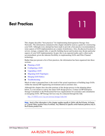
Best PracticesThe optimum SAN configuration depends on the I/O traffic, whether it be one-to-one,many-to-one, or any-to-any pattern.Core and Edge Switch ConceptIn the future, most large SANs will support any-to-any traffic patterns. The remainder of thischapter focuses on this problem.The optimum fabric configuration uses a high performance “core” surrounded by a number of“edge switches.” The core provides roughly equal connection performance between any pair ofports. The edge switches provide port aggregation to match the performance requirements ofthe servers and storage systems to the performance of the core.The figure below shows a large configuration that uses the core and edge switch approach.HostsStorageStorageHostsSHR-2584AFigure 85: Example of Core Switch Plus Edge Switch ConfigurationFabric Core OptionsThe simplest fabric core is a single switch. Fibre Channel switches support simultaneous fullbandwidth connections between any combination of port pairs. A single switch fabric coreguarantees support for any-to-any traffic.Any combination of switches has less performance than a single switch, and the differencedepends on the fabric topology. The best-performing topology is the “fat tree”, which hasenough Inter-Switch Links (ISLs) to provide, on the average, full bandwidth connectionsbetween any combination of port pairs. While it is possible to construct workloads that forcetraffic contention on the ISLs of a fat tree, which reduces the throughput, fat tree fabric coretopologies provide full-bandwidth any-to-any communication, on the average, for randomtraffic patterns.SAN Design Reference Guide297
Best PracticesA related topology is the “skinny tree”, which has fewer ISLs and fewer switches. Thistopology introduces an unavoidable performance limit to the fabric. In many cases this limit isbeyond what is required by the application servers. The process to upgrade a skinny treetopology to a fat tree topology is fairly straightforward, involving the addition of switches andISLs to the existing treeEdge Switch OptionsThe simplest edge switch is a single switch with one ISL connecting it to the fabric core. Eachedge switch provides “User Ports” for connecting servers and storage systems.The single ISL is a potential bottleneck. All the I/O traffic from the servers or storage systemsconnected to the edge switch must pass through just one ISL. More ISLs can be provided.Several combinations of ISL and user ports may be used. For example, with sixteen portswitches, the ISL to user port ratio could be 1:15, 2:14, 3:13, 4:12, etc. Each of thesecombinations represents a “port aggregation ratio.” The ratios are 1:15, 1:7, 3:13, 1:3, etc.The workload of the servers and storage systems attached to an edge switch determines therequired port aggregation ratio for the switch. For lightly loaded application servers, a 1:15port aggregation ratio may be adequate. Heavily loaded servers may require a 1:7 or 1:3 ratio.Extremely high performance servers, such as high-end HP Integrity or HP 9000 Series ofservers, may be able to completely “fill up” a Fibre Channel connection. In this case, there isno advantage to using an edge switch, and the server should be connected directly to the fabriccore. Storage systems may also be able to support a full bandwidth Fibre Channel connection.To select the appropriate port aggregation ratio, refer to the I/O requirements of yourapplications and servers. This information is available for many situations by using the ActiveAnswers application sizing tools. In other cases, measurements of an existing system may berequired to determine the workload.Designing a Subsettable SANIn many cases, the growth pattern for a storage installation is difficult or impossible to predict.Global economic growth, conditions in a given business market, the growth rate of yourcompany, and internal reorganizations or reallocations of computing resources may all have asignificant impact on the requirements that must be met by the SAN.To accommodate this unpredictable variability, the SAN designer should plan for growthwithin a predefined design. The initial installation should be a subset of a larger pre-designedconfiguration.The “core plus edge switch” approach supports this strategy for SAN design.When the time comes to expand an existing installation, the system manager can makeincremental changes to the configuration rather than a complete reconfiguration of the entireFibre Channel fabric. Changes to the fabric core are isolated from the edge switches, whichminimizes the impact of changes required to support core growth. Changes to a given server’sconnection to an edge switch are isolated from the core, which minimizes the impact ofserver-related changes. Furthermore, since two or more fabrics are in use, server I/O trafficmay be temporarily forced to a single fabric while the other fabric is undergoing modification.Start with a single switch core for a moderate sized initial installation,. When needed, the corecan be expanded by replacing the switch with one that has more ports, or by reconfiguring thecore to a skinny tree or fat tree topology. An existing fat tree core may be expanded byreplacing it with a fat tree made up of switches with more ports, or by reconfiguring it to awider fat tree configuration.298SAN Design Reference Guide
Best PracticesUse a generous estimate of the required I/O performance when selecting edge switches. A portaggregation ratio of 1:7 or 1:3 is adequate for most applications. Increasing bandwidth is asimple, localized modification, if it turns out that more is required.The initial design should include spare ports on the core to support the future addition of edgeswitches. For example, consider a configuration that uses sixteen port switches, a single switchcore, and edge switches with a port aggregation ratio is 1:3. This design supports up to fouredge switches and 48 user ports. This would be a suitable solution for a system where 36 portsare required now, requiring three edge switches. Future growth to 48 ports can beaccommodated by adding another edge switch.SAN Design Summary of RecommendationsEnterprise-level SANs should include the following features. Multiple independent fabrics. Core plus edge switch topology. Appropriate port aggregation ratio, depending on application server requirements. Appropriate core design, depending on number of ports required. Subsettable design, with initial installation suitable for current needs.By following these guidelines for SAN planning, your design will be suitable for supportingfuture storage technology and future growth in your storage environment.SAN Design Reference Guide299
Best PracticesConfiguring a SANOnce you have completed the planning phase you can begin to configure your SAN. Asdescribed in the planning phase, it is important that you document the configuration. Duringthe configuration phase, you should be recording the details of the actual physicalconfiguration. Recording. As you construct the SAN, record the cable connections and mark thisinformation on the configuration layout diagram. Record the WWN of all nodes anddevices and identify where they physically reside. It is recommended that you place a labelon each Fibre Channel HBA with the WWN clearly identified. HP storage systems arepre-labeled with this information; however, you may wish to place an additional label onthe front of the unit in plain view. Cabling. Define a system for cable labeling. Even a small SAN can include a very highnumber of fiber optic interconnect cables. Label both ends of each cable with the sameunique cable number or color code scheme. This will allow you to quickly identify eachcable uniquely. Also consider placing a label at each end of the cables that identifiesconnection points at both ends, such as “TO” and “FROM”. Use label types that are easyto create and read, and ensure they are attached securely to the cable. Protect unused or open switch ports with port plugs. Never leave ports exposed. Cable Dressing. Use care when routing fiber optic cable and ensure that you do not exceedthe recommended minimum bend radius. For single-mode and multi-mode fiber cable theminimum bend radius is 25 mm. Where cables are bundled or hanging unsupported, usevelcro tie wraps to group and support the cables. Never use plastic tie wraps as they candamage the internal fiber core if over-tightened. Cable Symmetry. When connecting cables, consider slot/port-numbering symmetry. Beconsistent across similar servers with cabling in terms of HBA slot placement and cablingto switches. If configuring with two SAN fabrics and multi-pathing, connect HBA 1 toSAN fabric 1, HBA 2 to SAN fabric 2, etc. Cable symmetry is not a requirement, butserves as an aid to troubleshooting if this is eventually required. Configure Fibre Channel Switches. Although all HP Fibre Channel switches arepre-configured, verify that all Fibre Channel switches in the fabric have the sameparameter settings and that each has a unique domain ID.Label switches using a relevant naming scheme particular to the topology. For example, ifimplementing a ring topology, label each switch in the ring as Ring1, Ring2. Although notan absolute requirement in all configurations, it is highly recommended that all switchesutilize the same switch firmware revision. Different switch code revisions running in thesame fabric are supported during a rolling upgrade. This is considered a temporarilyacceptable situation for the duration of the code update. Configure Servers. For each platform or operating system type, utilize the appropriate HPStorageWorks platform kit to ensure that the required server drivers and configurationsettings are loaded. Ensure that servers are configured with the proper operating systemversions and all required updates.Use a numbering type scheme for naming multiple servers of the same type, such as NT01and NT02 for Windows NT servers. 300Configure Storage. Use the storage map created in the planning phase to configure each ofthe storage systems. Verify server-to-storage connectivity, and access one server at a time.SAN Design Reference Guide
Best PracticesWhen initially defining storagesets, always disable all access first, and then enable thedesired individual access. For Enterprise/Modular RAID Array storage systems, defineconnection names to be consistent with zoning alias names. Be consistent with connectionnames relative to storage port and controller connection. Choose a scheme that is easilyunderstood and quickly conveys the physical connectivity. Define Zones. Use the zoning map to configure zones. Consider starting with small zonesthat allow a smaller logical subset of a larger physical SAN to be tested initially.Always save old zoning configurations before and after making any zoning change. Ifpossible, it is recommended that no zoning changes be made when an individual switchnormally configured in the fabric is temporarily not available.You can zone by operating system or by storage system. Zoning by operating systems isuseful when the operating systems are accessing storagesets that are localized to specificraid arrays. For example, NT1, NT2 and NT3 have access to storage on ARRAY1, andVMS1, VMS2 and VMS3 have access to storage on ARRAY2.ZONE NAME NT ZONEMembersNT1NT2NT3ARRAY1VMS ZONEVMS1VMS2VMS3ARRAY2ARRAY1 will only have host connections for the NT1, NT2 and NT3 servers andARRAY2 will only have host connections for the VMS1, VMS2 and VMS3 servers.Zoning by storage system will limit the connections to the G80 to those systems actuallyhaving storagesets on them. This is useful when the storagesets for a specific system areon multiple storage systems.In the above example, we add 3 more NT servers and another storage system to the NTzone:ZONE NAME NT ZONEVMS NT6ARRAY3Both Array1 and Array2 will have host connections from all 6 NT systems. This may notbe a problem in a small SAN, but as the SAN grows the connections will increase. Also,we do not know which of the NT servers are accessing storage on ARRAY1, and whichones are accessing storage on ARRAY2.The preferred method to zone is a combination of operating system and storage systemzoning.ZONE NAME NT ARRAY1 ZONE NT ARRAY3 ZONE VMS ARRAY2 MS3ARRAY2Zoning this way also makes it much easier to troubleshoot, especially if servers accessstorage on multiple arrays.SAN Design Reference Guide301
Best PracticesDue to some zoning restrictions, you may need more than one zone for a particularARRAY. If AIX ARRAY1 also has IBM AIX servers, we must zone that separately.AIX ARRAY1 ZONE1ARRAY1AIX 1AIX 2Zone and Zone Alias NamesWhen setting up zoning, use meaningful names for zones and zone aliases and be consistentwith the naming convention throughout the fabric.Servers are identified by the WWN of the host bus adapter. Name these by using the systemname and the host bus adapter number. For example, server NT1 with one Fibre Channel HBAwould have an alias of NT1 HBA1. Server NT1 with a second HBA would have an alias ofNT1 HBA2RA8000 storage systems in a transparent failover configuration will have two WWN's on thefabric, one for port 1 and one for port 2. Give each RA8000 a unique number. RA8000 number1 could have aliases of R1 P1 (port 1) and R1 P2 (port 2)For a multiple-bus failover configuration the RA8000 will present 4 WWNS to the fabric. Ifyou have a multi-path NSPOF configuration, two of the WWN's will be in one fabric, the othertwo will be in the second fabric. Name the ports using an alias such as R2 A1 (Controller APort 1), R2 A2 (Controller A Port 2), R2 B1 (Controller B Port1), and R2 B2 (Controller BPort 2).Ports A1 and B2 will be cabled to the first fabric. Ports A2 and B1 will be cabled to the secondfabric. The aliases in fabric 1 will be R1 A1 and R1 B2, the aliases in the second fabric willbe R1 A2 and R1 B1. Keep the ports and HBAs the same throughout the setup. For example,always have HBA 1, R1 A1 and R1 B2 in fabric1 and HBA 2, R1 A2 and R1 B1 in thesecond fabric.Using this convention conveys the failover mode that the RA8000 is configured for. Any aliaswith a P1 or P2 is in transparent mode, any alias with A1, A2, B1, or B2 is in multiple-busmode.Define RA8000 host connection names for the adapter WWN's in the same manner as youdefined the alias name in the fabric. For example, the fabric alias name for NT1, HBA1 will beNT1 HBA1. The host connections on the RA8000 controller should match this as closely aspossible.Example:Alias NT1 HBA1 in the fabric would have host connection names on the RA8000 of:NT1-P1 WINNTTHIS1HOST ID 2000-0000-C922-8ADC081200 OL this 30ADAPTER ID 1000-0000-C922-8ADCNT1-P2 WINNTOTHER 2HOST ID 2000-0000-C922-8ADC081200 OL other 130ADAPTER ID 1000-0000-C922-8ADCNote: While storage system connection names are not case sensitive, switch alias names are. Thatmeans that the switch might have a alias name of TRU64 1 and another alias name of Tru64 1 thatrefer to two different sets of things.302SAN Design Reference Guide
Best PracticesUpgrading a SANUpgrading a Fibre Channel SwitchSee the Installation and Hardware Guide for your switch.Scaling a SANThe information in this section applies to all SAN topologies, whether a custom design or HPdefined. Replace 8-port switches with 16-port switches. Add additional switches, up to the limits specified for a single fabric in Chapter 3, "SANFabric Design Rules". Add a second fabric as a high availability no single point of failure solution. Deploy multiple independent SANs. Migrate to a different topology (see below).Scaling Specific SAN TopologiesThe information in this section is specific to the HP-defined topologies. Refer to the FibreChannel switch replacement procedure elsewhere in this chapter for information aboutpreventing fabric segmentation when adding new switches to an existing fabric.Whenever you are expanding a topology, ensure that the new switch and device connectivity isconsistent with the original SAN topology design requirements and goals. Avoid makingchanges to the topology that may serve to disrupt the original topology design goals. If youneed to make topology changes based on a change in data access requirements, considermigrating to a different topology that is better suited to meet these needs. It is important in anyexpansion that the original data access needs be maintained.If you have implemented a high availability fabric design (refer to Chapter 2, "SANTopologies"), it may be possible to expand your SAN in a non-disruptive manner. It is highlyrecommended, however, as a precaution, that all data be backed up and that I/O activityquiesced when adding new switches to the fabric.Cascaded FabricExpand an existing cascaded fabric by connecting a new switch to an available port on anexisting switch. If there are no available ports, remove a device or set of devices from anexisting switch, connect the new switch to those ports, and connect the device or devicesto the new switch.Meshed FabricExpand an existing meshed fabric by connecting a new switch to available ports on anexisting switch. If there are no available ports, remove a device or set of devices from anexisting switch, connect the new switch to those ports, and connect the device or devicesto the new switch. To maintain the meshed topology, you must ensure that there aremultiple paths (ISLs) connecting the new switch to the existing meshed fabric.Ring FabricExpand an existing ring fabric by breaking the ring and inserting another switch into thering.SAN Design Reference Guide303
Best PracticesAdd new switches cascaded off of the ring, up to the maximum number of switchessupported in a single fabric. When expanding outside of the ring, ensure
Best Practices 294 SAN Design Reference Guide Planning a SAN Proper planning considers both present and future requirements. This can be accomplished by over-planning your initial SAN capacity and connectivity requirements to accommodate expected future needs. Whether using an HP standard topology or designing your own