Transcription
Petri Net Inside RFID Database Integrated withRFID Indoor Positioning System for MobileRobots Position ControlJosé Jean-Paul Zanlucchi de Sousa Tavares, Rodrigo Hiroshi Murofushi, LucasHenriques Silva, and Gustavo Rezende SilvaManufacturing Automated Planning Laboratory (MAPL), Faculdade de EngenhariaMecânica (FEMEC), Universidade Federal de Uberlândia (UFU), Uberlândia, Brazil.jean.tavares@ufu.br, {hiroshihm, @hotmail.comAbstract. The advent of industry 4.0, internet of things and smartproducts increase the importance of solution focused on machine-tomachine communication. There is a need for a solution that meets thesecharacteristics and the Petri Net integrated with RFID (PNRD) canreach them. There are a lot of papers connect the Petri Net to RFIDby creating the network markings based on the reading of the tags. ThePNRD uses the Petri net as the formal data structure to be stored inthe tag memory, increasing Petri Net and RFID integration. RFID canalso be useful as indoor positioning system or IPS. This work proposesto integrate PNRD and IPS in order to store the object process modelin the tag, as well as its position obtained by the IPS can become aprerequisite of the process itself. A case study presents a mobile robotposition control based on PNRD and IPS integration.Keywords: Indoor Positioning System, Radio Frequency Identification,Petri Net Inside RFID database – PNRD, Mobile Robot Position Control1IntroductionThe advent of industry 4.0 [1], the internet of things (IoT) [2, 3], and smart product [4] make solution focused on device-to-device communication. Continuing touse systems development methodologies focused on human-machine interactionis a challenge in relation to machine-machine solutions. There are highlightedtechnologies with respect to this machine-machine iteration, especially with regard to operational issues. One of them, pointed as product DNA and information key source, is RFID (Radio Frequency Identification) that allows processand product monitoring, tracking and control [5]. Since the initial RFID application with the Walmart initiative in early 2000’s, much attention has been pointedout for this technology. The current RFID market shows that it has been overestimated. Nowadays the RFID implementation is below its potential withoutprocess information embedded adding automatic data and process capture.
158PNSE’17 – Petri Nets and Software EngineeringNumerous researchers that relate RFID and Petri Net present solutions inseveral different areas such as quality management of a process [6], logistic process modelling [7], healthcare [8], control design of flexible cells of manufacturingsystem [9], monitoring and control of assembly and disassembly systems [10],material management among others [5]. These applications have a low-level connection between Petri Net and RFID, and they focused on the creation of thePetri Net marking generation based on the reading of the tags.The PNRD [11] provides a formal data structure to tagged objects, whichdefines and introduces the process activity into a RFID disperse database. Inthis way, the tag stores its own Petri net (incident matrix and object actualstate), and readers have the control vector associated with the reading activityand another conditioning sentence allowing the automatic object Petri net nextstate calculation, as well as updating its own state vector after the calculation.Since the tag refers to a single object, the PNRD must be a safe Petri net, andthe calculation of the next state must be a unitary vector. Any result otherthan a unit vector identifies an inconsistency in the process of tag, and it isviewed as an exception. A software called DEMIS (Distributed EnvironmentManufacturing Information System) performs the next PNRD state calculation.The RETIM (Real Time Item Monitoring) software graphically displays the tagcorresponding Petri net model and actual state in real time.Another RFID feature is the object localization through an Indoor Positioning System (IPS), which determines the position of an object in an indoorenvironment. Recent IPS techniques based on RFID generally uses the ReceivedSignal Strength (RSS) information to estimate the location of a tagged object[12]. IPSs can be used for different applications that can range from detectionand tracking of items, production assistance, and process monitoring [13]. Withthe development of automation and control, different industries rely more onIPSs for their operations such as robotic guidance, industrial robots, robot cooperation, and smart factories [14].The PNRD approach integrated with IPS increase the value of RFID technology and it provides an example, in which the RFID implementation can beseen as a positioning sensor (IPS), and as an automatic data and process capturetool. In this context the RFID technology cannot only reach intelligent productrequirement, as well as, it can be useful as IPS tool inside the smart factoryapproach, too. This work proposes to integrate PNRD and IPS so that the dataand process is stored in the tag data memory, as well as it is possible to obtainthe tag position by the IPS. A case study of a mobile robot with a passive tag ispresented, in which the mobile robot changes its movement direction dependingon the vehicle’s distance from the reader antenna. The PNRD stores the Petrinet incidence matrix as well as the robot actual state. This state changes according to the calculated distance. The vehicle moves away from the reader antennawhenever the distance is less than 35 cm and it approaches the reader antennawhenever the distance is greater than 70 cm.This article presents Petri Net and RFID review in section 2. Section 3 showsPNRD and IPS integration purpose. Section 4 describes the mobile robot imple-
Tavares et.al.: Petri Net Inside RFID Database Integrated with . . .159mentation. Conclusions are presented in section 5, followed by acknowledgmentsand references.22.1Petri Net, RFID and IPSPetri Net and RFID IntegrationOn one hand, PNs provide the formal foundation formal modeling concurrencyand synchronization [15]. PNs have been successfully used to model, control, andanalysis discrete event dynamic systems that are characterized by concurrency orparallelism, asynchrony, deadlocks, conflicts and event-driven processes [2]. Onthe other hand, RFID is an automatic identification and data capture (AIDC)technology with usually presented as composed by three parts, RFID tags thatis connected physically to objects; RFID reader that generates an electromagnetic field to stimulates RFID tag response when it is near enough; and RFIDmiddleware that cares about data filtering, reader management, and applicationconnection. There are many papers integrating RFID and PN.Chen [9] build a CPN models for different modules of FMS (Flexible Manufacturing System), to plan RFID codes rules of FMS and to develop a cellcontroller for RFID-based on a centralized FMS cell controller. This article provides a suggestion for mapping between color tokens of place in the CPN andthe data memory of RFID tags. Petri Net model defines RFID read & writeaction. RFID tag data is position sensitive, and the implementation used a lowfrequency reader and tag.Sun et al. [10] proposed an assembly executive process Petri net (AEPPN)integrating Petri nets and mobile agent-based complex product assembly framework. This approach describes states of assembly as PN transitions, events inassembly executive process as PN places and mapped to RFID tags states, whichare able to trigger dispatching of assembly agents and executive of assemblytasks. AEPPN is a set of places, transitions, color set, input function, outputfunction, initial marking and time delay transition. The mapping relationshipbetween the product set and the color set is 1:1. In each net, the amount oftoken with an exclusive color is 1 and only 1. RFID tag’s states can be used todescribe the assembly executive process state. AEPPN can acquire, delete, create or update Tag data; therefore the AEPPN is center-controlled but executeddispersedly. RFID tags can also be regarded as offline communication channels.Lv et al. [6] developed RFID-based CPN to improve the quality of the system without sacrificing any one of the performance parameters. RFID systemelements, which are connected bidirectionally with CPN, can update informationpromptly with real-time action. RFID tag and color token stored the informationof the product in a manufacturing system, and both of them can update the status of product simultaneously. This approach combined RFID and CPN for simulation analysis. CPN simulation results can help update the RFID database, andboth databases can be synchronized. This research developed the RFID-basedcolored Petri net to finish the accurate real-time analysis for the manufacturing
160PNSE’17 – Petri Nets and Software Engineeringsystem, so as, to realize automatic abnormity handling and enhance decisionmaking. CPN token color remains the same after transition activity if this processing developed smoothly. Otherwise, color changing indicates failure modeshappening in the last transition activity. Once the color of the token changes, thereader antenna sensor receives a signal that the status of the product changed.Then the reader rewrites the stored information and sends the new data to hostapplication. Host application feedbacks a corresponding process activity on thecolored changed token, for example, the failure part needs rework by reentrant.Zhang et al. [2] presented a real-time production performance analysis andexception state diagnosis model (PAEDM). By combining RFID, hierarchicaltimed-colored Petri Nets (HTCPN) with decision tree algorithm, this paperproposes a real-time production performance analysis and exception diagnosis model. The proposed architecture relies on three modules. The first one isIoT-enabled shop-floor module that is a bridge for information communicationbetween physical manufacturing systems and the process. The second moduledeals with dynamic behavior model of the manufacturing system and data capture processing. The third module corresponds to decision tree-based exceptionand cause diagnosis. It presented a case scenario from a collaborative companyusing high-frequency RFID tags and readers. There was a need for integrationwith CAD/CAM/CAPP systems to perform the presented case.Guo et al. [16] proposed a timed colored Petri net simulation-based selfadaptive collaboration method for Internet of Things-enabled production-logisticssystems. The method combines the schedule of token sequences in the timed colored Petri net with real-time status of key production and logistics equipment.The proposed framework is composed of three layers, namely physical layer, cyber layer and the application one, where a Timed Colored Petri Net (TCPN)model is developed to depict and control the behavior of key equipment byadjusting the schedule of token sequences. In the simulation, a personal computer, fifteen antennas, four RFID readers, and nine RFID tags were used. TheRFID tags were attached to different manufacturing objects, such as machines,AGVs, and WIP. The TCPN model started running at the same time when theproduction and logistics were executed according to the planned time. Firstly,real-time status information of machines, AGVs, and work in process (WIP)was transmitted to the PC through RFID reader ports. Secondly, based on thecollected information, the objective functions were implemented and the resultswere stored in Standard ML (SML) files. Thirdly, every time the cycle of theTCPN model started, the information in the SML files was updated. By loading SML files, the status of colored tokens was tuned accordingly. ComparingTCPN based self-adaptive collaboration method with an event-driven method,total waiting time reduced 28,8%, makespan decreased 16,5%, and total electricity consumption down 4%.Jiang et al. [17] presented a Petri-Net model-driven methodology for thedevelopment, validation, and operation of a RFID-enabled decentralized FMS.A methodology to define active and passive elements was presented in orderto each active resource is equipped with a reader and each passive resource
Tavares et.al.: Petri Net Inside RFID Database Integrated with . . .161is banded with a tag. Active resources acquire the status of passive ones byanalyzing the PN models; they decide the next steps by combining their ownstatus and behavior logic.The Color Petri Net model presented two distinguishedplaces, it means, state-place for real-time status of the equipment, and port-placefor an interface of workpiece and storage equipment.It can be noticed that most of these applications have a low-level connectionbetween Petri Net and RFID usually generated by the color token relationshipwith RFID tag reading, it means they focused on the creation of the Petri Netmarking identification based on the reading of the tags in a centralized PNcontrol model. In the case of Jiang et al. [17], RFID is the product databaseitself for operational level management; however, it is not clear how strong thisconnection is.2.2PNRDAccording to [11], the PNRD - Petri Net Inside RFID Database - is a RFIDdata structure based on the elementary Petri Net formalism or Low-Level PetriNet (LLPN), and it can be described as a five-tuple (P, T, A, w, M0 ), whereP is the finiteS set of places, P 6 , T is the finite set of transitions, T 6 .A (P T ) (T P ) IN is the set of arcs from places to transitions andfrom transitions to places, w : A {1} is the unit weight function on the arcs,and M0 : P {0, 1} is the PN initial marking. As PNRD has a 1:1 relation witheach tag, and PNRD must be a safe Petri net with only one weight function,and a unitary marking. In this approach each tag stores its own incidence matrixand state vector of a Petri net referring to the process part to which the taggedobject in question participates; and each reader stores the corresponding controlvector list and the triggering conditions. The PNRD operation is based on thecapture of the tagId followed by the AT or incidence matrix, and the tag statevector (Mk ). The software responsible for calculating the next state finds thecorresponding uk (control vector) related to the conditioning set composed bytagId, tag state, antennaId, readerId, and other optional additional data, suchas time interval, the distance among other. The calculation of the next tag stateMk 1 follows (1).Mk 1 Mk AT ukk 1.n .(1)The next tag state result must be evaluated. If the result is a unitary vector,this means that the Petri net remains elementary and safe, which is consistentwith the fact that each tag has a 1: 1 relation with Petri Nets. This result issupposed in agreement with the expected process flow, allowing the record of theMk 1 in the tag memory as new tag state. Otherwise, the Petri net is no longersafe, indicating an abnormality in the expected follow-up of the process, whichcan generate a real-time warning signal. It is able to monitor the process of eachtag individually. Even flexible processes can be stored, giving to the tagged objectthe ability to follow different paths as long as properly planned and modeledpreviously. One of the possible problems during the execution is the appearance
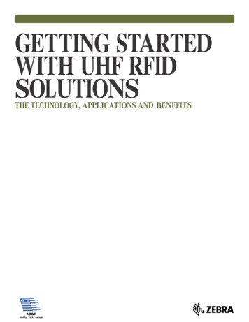
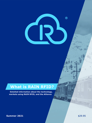
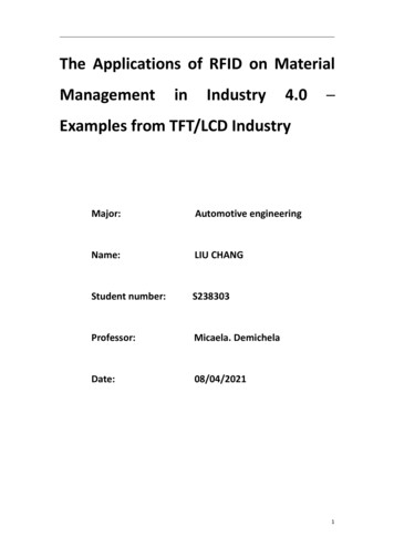
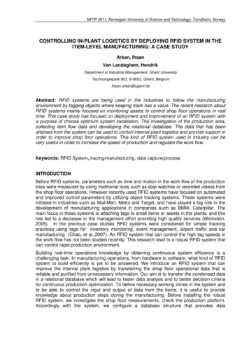
162PNSE’17 – Petri Nets and Software Engineeringof conflicts. Conflicts occur when the same antenna/ reader is associated withmore than one transition relative to the same tagId, tag state, and additionaldata. A decision algorithm can be applied to choose what transition should betriggered in order to solve the conflict and more details was presented in [11].Hence, PNRD is based on a previously modeled system, and it is able to checkwhether the desirable model is followed or not.It is possible to point out that in the PNRD approach there is a strongconnection between RFID and Petri Net, which reduces the need for queries inexternal databases. In the other hand, it is evident that the PNRD approachuses an additional step of capturing data related to the incident matrix andthe control vector. In this direction, the process of the tagged object must bepredefined in advance. After this process modeling, an operational managementsystem must attribute a specific PN process to each tagged object.To explain PNRD didactically, Fig. 1 shows an aerospace product selection example. In this process, the product must be tested twice. The first selection defines whether the product can be sent to industrial Companies byT est1Acceptance transition or not, it means, it must be sold as a replacement item by T est1Rejection transition. The industrial supply item must beselected as aerospace supply by T est2Rejection transition or military one byT est2Acceptance transition. Since the PNRD is the Petri Net of the tagged object point of view and this object is one and only one, physically, it is not possibleto split an object identification as an AND-split transition. In this example, thereis no AND-split transition, so, the original Petri net model is identical to thePNRD model. In the PNRD model, there is a need for identifying the reader antenna associated with each transition. In this case, transitions T est1Acceptanceand T est2Rejection are connected with Reader1 – Antennas 1/2, and othertransitions have a distinguish reader antenna, for instance, T est1Rejection isconnected with Reader1 – Antenna 3, and T est2Acceptance is connected withReader1 – Antenna4. An initial marking is included in AerospaceP roduct state,as presented in Fig. 2.Fig. 1. The Petri Net Model of the Aerospace Product Test Process
Tavares et.al.: Petri Net Inside RFID Database Integrated with . . .163Fig. 2. The Aerospace Product Test Process Schema With PNRD Model, Initial Marking, Incident Matrix, Readers/Antennas and Control Vector ConditionsFigure 2 also presents the schema of the physical layout with one reader1and four antennas installation. Each tagged Aerospace Product stores tagId,PNRD incident matrix, and tag state (represented by the tag initial markingM0 ). Each control vector has specifics conditions as if reader1 – antennas1/2captures a tag data, the control vector must be [1, 0, 0, 0]T (T est1Rejectionactivity), unless tag state is equal to [0, 0, 1, 0, 0]T where the control vectorchanges to [0, 0, 1, 0]T (T est2Rejection activity). This distributed data allowsthe automatic next state calculus during tag data capture by a specific reader.As an example, if the reader1 – antenna 1/2 captures one tag in the state M0(AerospaceP roductstate), then the next state calculation result is theReplacementItem state as presented in (2).M1 M0 AT u1 (0, 1, 0, 0, 0)T(2)As the PNRD model must be a one-safe Petri Net, the tagged AerospaceProduct cannot be in more than one state. This feature allows an automaticexception state detection. For instance, if an AerospaceP roduct is in theReplacementItem state and reader1 – antenna 3 is triggered, the result of thenext state calculation identifies and absent of token in the AerospaceP roductstate, one token in the IndustrialSupply state and a remaining token in theReplacementItem state (3).M2 M1 AT u1 ( 1, 1, 1, 0, 0)T(3)DEMIS – Distributed Environment Manufacturing Information System DEMIS or Distributed Environment Manufacturing Information System is
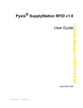
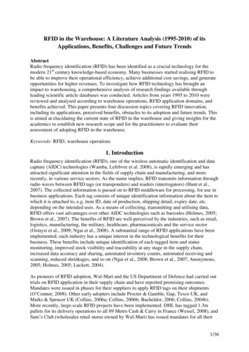
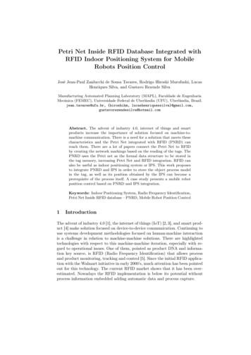
164PNSE’17 – Petri Nets and Software Engineeringan implementation of PNRD in software based on Java technology. The DEMIShas two modules: the PNRD core and the interfaces one. The interface moduleis responsible for communicating with the various devices, such as RFID readers, PLCs - Programmable Logic Controller, and the interpretation of the datasent and received. The DEMIS Core has the next state calculation algorithm orPNRD Engine; an Inference Machine with a knowledge base to solve conflicts;and configuration files (ips, port, the number of readers’ antennas, control vectorlist and tags state pre and post conditions). Figure 3 presents, in a simplifiedway, the DEMIS architecture.ReTIM – Real Time Item Monitoring Since each tag stores its own process data and process, it is possible to visualize the object operational state andprocess, graphically. The ReTIM software integrates the concept of process remote monitoring related with individual tagged object. After DEMIS calculatesthe next state, it sends a message to the ReTIM with reader/antennaId, tagId,incident matrix and tag state. Then ReTIM can graphically display the PetriNet of the object and its respective state [18]. Figure 4 shows an example of atag data capture from DEMIS integrated with ReTIM to graphically visualize aPetri Net with four places, four transitions, and the marking in the P4 state.Fig. 3. DEMIS Architecture adopted from [11]
Tavares et.al.: Petri Net Inside RFID Database Integrated with . . .165Fig. 4. Example of ReTIM interface with DEMIS2.3IPS (Indoor Positioning System)There are two types of RFID indoor positioning system, i.e., reader localization,and tag localization depending on what, between reader and tag, needs to belocalized. In the reader localization, the accuracy of the RFID system is highlydepending on the density of tag deployment and the maximal reading ranges. Ina probable localization context, a large number of RFID tags, which contain itsown location information, can be deployed to cover an entire indoor environment.The disadvantage of this approach is the large number of RFID tags, which needto be applied, and prerecorded in advance with location information. Obviously,this method is more expensive and the cost increases with the increase in thenumber of used RFID readers [19].Related with IPS algorithms, there are four types, it means, Time of Arrival(TOA), Time Difference of Arrival (TDOA), Angle of Arrival (AOA) and Received Signal Strength (RSS). RSS estimates the distance of an unknown nodeto reference node from some sets of measuring units using the attenuation ofemitted signal strength. This method can only be possible with radio signals.RSS localization method could be using either a propagation model algorithmor a fingerprinting algorithm. Propagation Model Algorithm (PMA) establishesthe model between RSS and the distance. Generally, the higher of the RSS values the closer from the Access Point (AP) the tagged object is. Attenuation ofthe received signal strength is inversely proportional to the distance from AP
166PNSE’17 – Petri Nets and Software Engineeringin the outdoor. In contrast, it is complex in the indoor environment because ofthe existence of obstacles (furniture, equipment windows, doors etc.) may causemultipath propagation, such as reflection, refraction, and diffraction [14].Indoor localization of autonomous vehicles (or mobile robots) is a challengingand lively subject because of the complexity of the indoor scenarios, the diversityof technologies involved, and the commercial and industrial interests [20] andone possible way of estimating a robot position makes use of the RFID. Thissubject has received a considerable attention in the last few years and in manycases, the localization system is realized by installing a reader on the robot andby providing the environment with a certain number of tags placed in knownposition [13, 21–23]. Applying formal methods to model robot tasks like Petrinet provides a systematic approach to modeling, analysis, and design, scaling upto realistic applications, and enabling analysis of formal properties, as well asdesign from specifications [24].There are also many papers about IPS based on RFID technology and themain purpose of this subsection is to present some works related to mobile robotlocalization.DiGiampaolo and Martinelli [22, 23] propose a global localization systemcombining odometry data with RFID readings. The RFID tags are placed onthe ceiling of the environment and can be detected by a mobile robot unit traveling below them. The detection of the tags is the only information used in theproposed approach (no distance or bearing to the tag is considered available),but only a small number (about one each square meter or less) of tags are used.This is possible using a suitable tag’s antenna in a ultrahigh frequency band,expressly designed to obtain regular and stable RFID detection regions. A satisfactory performance is achieved, with an average position error of about 0.1m.Martinelli [20] proposes a global positioning system based on the receivedsignal strength and the phase shift of UHF-RFID signals coming from a set ofpassive tags deployed on the ceiling of the environment together with odometry provides the position of a mobile robot. A multi-hypothesis extended andunscented Kalman filter is proposed to localize the robot and to simultaneouslyimprove the initial estimate on the tag coordinates.Murofushi et al. [25] and Murofushi and Tavares [26] designed a real timeunidimensional indoor positioning using passive tags based on the RSS of thebackscattered signal. The IPS design was based in the system calibration, andthe distance estimation phase. The IPS accuracy achieved is 4.7 cm for a mobilerobot moving at constant velocity.Errington et al. [27] investigate the concept of using an array of RFID tagsplaced at fixed known positions to provide the initial position to the Simultaneous Localization and Mapping (SLAM) algorithm. The mobile vehicle has aRFID tag reader coupled to it and the antenna is used to detect the tags. Theapplication of interest here involves determining the initial position of a stationary vehicle in an underground mine using an array of RFID tags placed at knownpositions to provide the initial position of the vehicle. The results suggest that
Tavares et.al.: Petri Net Inside RFID Database Integrated with . . .167RFID-based positioning, using the Least Square approach, has the potential toprovide relatively accurate and low-cost initial position estimation.3PNRD and IPS Integration ProposalThe proposal of this article relies on increasing RFID and Petri Net operationalpotential application based on IoT approach, it means, to use RFID system asa process aware based on PNRD approach integrated with an IPS.In this sense, RFID IPS sensor must become a pre or post condition enablingor inhibiting one or more PNRD transitions. This arrangement changes PNRDfrom ordinary to a high-level PN. It is necessary to complement the PNRDformalism with the pseudo-box concept, which denotes an observable conditionthat is not controlled by the modeled PN; and disabling arc [28].As presented in [28], pseudo-box is a hierarchical resource embedded in PetriNet, that is, elements that only propagate information and preserve the marking in its original place. It could be an enabling gate, that is, one that sendsinformation if is marked, or an inhibitor gate, if propagates information when isnot marked. Thus, these gates must always have an original place in Petri Netgraph, a special place called pseudo-box.Pseudo-boxes denotes an observable condition that is not controlled by themodeled system. During the course of the modeling, pseudo-boxes could alsostand for control information external to the hierarchical components and couldbe collapsed when components are put together. Thus, pseudo-boxes must beconsidered in the structure of the net but should not affect its properties or therank of the incidence matrix.This high-level Petri Net is a five-tuple(L, T, A, w, M0 ), where L is the finiteSset of places and pseudo-box,L BP,L6 , T is the finite set of transitions;ST 6 , A (L T ) (L P ) IN is the set of arcs from places or pseudo-boxto transitions and from transitions to places or pseudo-box; w : A {1} is theunit weight function on the arcs; and M0 : P {0, 1} is the PN initial marking.Hence, PNRD extended to distance is the original PNRD with pseudo-boxand disabling arc. This new information is calculated and storage at the readerand Fig. 5 shows its correspondent sequence diagram. If the precondition response identifies a required distance range, this generates a new operation inorder to determine tag distance and check if it is inside transition disabling therule. If so, next state calculation is realized. In this case, the internal applicationruns PNRD and IPS algorithm.Next section presents the case study of a mobile robot position control usingPNRD extended to distance approach.4Case Study: Implementation of PNRD and IPS inMobile Robot Position ControlThe case study presented in this work is about a mobile robot controlled by thePNRD. The vehicle moves forward or backward from 35 to 70 cm in an oscillating
168PNSE’17 – Petri Nets and Software EngineeringFig. 5. Sequence diagram of proposed PNRD extended to distancecycle. Figure 6 shows a scheme of the mobile robot position control. The mobilerobot uses two stepper motors, it has a short dipole tag attached, and an ArduinoUno R3 controls it. The reader is a reader M6e micro with a monostatic antenna.DEMIS and IPS were implemented in java programming language in an Intelcore I5 750, 2.66GHz, 8 GB RAM DDR3 in Windows 10 Pro 64 bit platform.The algorithm takes about 200ms for each position estimation ( data processingoperation) and the vehicle was programmed to move at a constant velocity of100 mm/s. Therefore, the mobile robot positioning error is lower than the IPSaccuracy of about 57 mm. Therefore, the identification of the position of therobot by the IPS can be identified as in real time.4.1Mobile robot position control Petri net modelFigure 7 presents mobile robot Petri net model with places (white circle) andpseudo-box (gray circles), transitions, arcs and disabling arcs. There are fourplaces, InitialM arking (P 1), M obileRobotStandBy (P 2), F orwardM ovement(P 3) and BackwardM ovement (P 4) and five pseudo-box DistanceM easurement(P s1), F wdM ovM essage (P s2), BckM ovM essage (P s3), StopF wdM ovM e
puter, fteen antennas, four RFID readers, and nine RFID tags were used. The RFID tags were attached to di erent manufacturing objects, such as machines, AGVs, and WIP. The TCPN model started running at the same time when the production and logistics were executed according to the planned time. Firstly,