Transcription
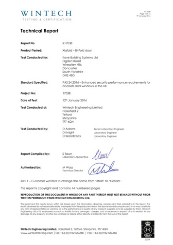
9thR17038Page 1 of 15January 2016Technical ReportReport NoR17038Product Tested:Xlafold – Bi-Fold doorTest Conducted for:Kaye Building Systems LtdOgden RoadWheatley HillsDoncasterSouth YorkshireDN2 4SGStandard Specified:PAS 24:2016 – Enhanced security performance requirements fordoorsets and windows in the UKProject No:17038Date of Test:12th January 2016Test Conducted at:Wintech Engineering LimitedHalesfield 2TelfordShropshireTF7 4QHTest Conducted by:D AdamsD KnightD WoodcockReport Compiled by:S TawnAuthorised by:M WassSenior Laboratory EngineerLaboratory EngineerLaboratory EngineerLaboratory ApprenticeTechnical DirectorRev 1 – Customer wanted to change the name from ‘Xfold’ to ‘Xlafold’.This report is copyright and contains 14 numbered pagesREPRODUCTION OF THIS DOCUMENT IN WHOLE OR ANY PART THEREOF MUST NOT BE MADE WITHOUT PRIORWRITTEN PERMISSION FROM WINTECH ENGINEERING LTD.This report and the results shown within are based upon the information, drawings, samples and tests referred to in the report. Theresults obtained do not necessarily relate to samples from the production line of the above named company and in no way constituteany form of representation or warranty as to the performance or quality of any products supplied or to be supplied by them. WintechEngineering Ltd or its employees accept no liability for any damages, charges, cost or expenses in respect of or in relation to anydamage to any property or other loss whatsoever arising either directly or indirectly from the use of the report.Wintech Engineering Limited, Halesfield 2, Telford, Shropshire, TF7 4QHwww.wintechtesting.com Tel: 44 (0)1952 586580 Fax: 44 (0)1952 586585
9thContents1.2.3.4.5.6.7.IntroductionSummary of Test ResultsDescription of Test SampleTest ArrangementTest ProceduresTest ResultsSystem DrawingsPage No.334781014Wintech Engineering Limited, Halesfield 2, Telford, Shropshire, TF7 4QHwww.wintechtesting.com Tel: 44 (0)1952 586580 Fax: 44 (0)1952 586585R17038Page 2 of 15January 2016
9th1.R17038Page 3 of 15January 2016IntroductionThis report describes testing of a door sample conducted at the test laboratory of Wintech EngineeringLtd on behalf of Kaye Building Systems Ltd in order to determine compliance with PAS 24:2016.Wintech Engineering Ltd is accredited by the United Kingdom Accreditation Service as UKAS TestingLaboratory No. 22232.Summary of ResultsThe following summarises the results of testing carried out, in accordance with PAS 24:2016Test DescriptionResultAnnex A – Security hardware and cylinder testB.4.6 - Manual check testB.4.4.3 - Infill – mechanical testB.4.3 - Manipulation test (a)B.4.4.4 - Manual cutting testB.4.5 - Mechanical loading testB.4.4.2 - Infill – manual testB.4.8 - Soft body impact testB.4.9 - Hard body impact testOverall Classification in accordance with PAS 24:2016PassPassPassPassPassPassPassPassPassDMore comprehensive details are reported in Section 6.Note: These results are valid only for the conditions under which the test was conductedNote: All measurement devices, instruments and other relevant equipment were calibrated and traceable toNational Standards.Wintech Engineering Limited, Halesfield 2, Telford, Shropshire, TF7 4QHwww.wintechtesting.com Tel: 44 (0)1952 586580 Fax: 44 (0)1952 586585
9th3.R17038Page 4 of 15January 2016Description of Test SampleProduct range name:Xlafold – Bi-Fold doorConfiguration:3 Pane (3-3-0)Opening direction:Right to LeftOuter FrameOuter frame width:2768mmOuter frame material:Outer frame height:Outer frame PartNumbers2200mmOuter frame gasketEPDM / PolypileGasket type:Top:KBF7101Bottom:KBF7101Lock side:KBF7101Hinge side:Outer frame sectionsizeKBF7101Manufacturer:Product name:Product code:ThresholdExlabesa / SchlegelFrame Gasket / FrameWoolpileKGF01 / KWP48825WFN/AManufacturer:Width:90mmProduct name:Depth:48mmProduct r:Material:Outer frame jointmethodMitred and CleatedProduct name:Head:4 x CLT1817Product code:Foot:4 x CLT1817Material:LeafLeaf width:887mmLeaf material:Leaf height:2118mmLeaf gasketLeaf Part NumbersAluminium/PolyamideGasket F7103Product name:Frame GasketLock side:KBF7103Product code:KGF01Hinge side:KBF7103Leaf section sizeLeaf midrail:Manufacturer:Width:75mmProduct name:Depth:62mmProduct code:N/AMaterial:Reinforcing:Manufacturer:N/ALeaf joint methodProduct name:Head:4 x CLT1328Product code:Foot:4 x CLT1328Material:Wintech Engineering Limited, Halesfield 2, Telford, Shropshire, TF7 4QHwww.wintechtesting.com Tel: 44 (0)1952 586580 Fax: 44 (0)1952 586585
9thR17038Page 5 of 15January 2016GlazingGlass unitGlasscraftGlazing gasketGasket type:Manufacturer:Inner thickness:4mmManufacturer:Spacer material:20mmProduct name:Outer thickness:4mmProduct code:Unit sizes:28mmBeadCaptive Outer /Wedge InnerExlabesaKGW20C / KGW045Glazing clipManufacturer:Manufacturer:ExlabesaProduct name:Product name:Product code:Product code:28mmBeadKBF005Bead size:20 x 17.5Manufacturer:Bead material:AluminiumProduct name:N/AGlazing tape detailsN/AProduct code:HardwareManufacturer:Hinges:Hinge fixing:Hinge protectors:Hinge protectorfixings:ExlabesaAnixterProduct description:Product code:Bi-Fold Hinge-BlackM5 x 10 M/C ScrewsNo 8 x 1” SelfTapping cskKBFHBKFMC0510KFSC0825Quantity:108 each2 eachN/AN/AMaster Door LockDoor lock:Door lock fixings:Master LockKeeps:Keep fixings:Shoot rComponentsDirectAnixterFuhrShoot Bolt fixingsAnixterShoot Bolt KeepFuhrShoot Bolt KeepfixingsAnixter856 Type 10 MultiLockM4 x 45 csk screwsM4 Tee NutsNo 8 x 1-1/4” Self TapcskOne piece keepM4 x 40 csk screwsM4 Tee NutsNo 8 x 1-1/4” Self TapcskTop shoot boltBottom shoot boltNo 8 x 2” SelfTapping cskTop Keep / Strike PltBtm Keep / Strike PltM6302DBOSJ1M4 x 45 00JNA002A-NATKFSC0830Top – MV150186SBtm – MV1508B6S99711KFSC0850RUD84662LX / RD5185XRUD84662RX /RD5518X2 EAKFSC0820KFSC08302 EA2 EANo 8 x 1” SelfTapping cskWintech Engineering Limited, Halesfield 2, Telford, Shropshire, TF7 4QHwww.wintechtesting.com Tel: 44 (0)1952 586580 Fax: 44 (0)1952 5865851 EA1 EA
9thR17038Page 6 of 15January 2016No 8 x 1-1/4” Self TapcskCylinder:Cylinder fixing:Handle:Handle fixings:DGSPart ofCylinder SetKBF5050C1Atlanta SBD36855011ExlabesaTop GuideKBFTGB1ExlabesaBottom RollerKBFBRB1ExlabesaShoot BoltKBFLKS1ExlabesaShoot Bolt RodsKBFSBKS2ExlabesaVerso HandleKBFVHEB1ExlabesaHalf CylinderK4510HC1HoppePart of HandleSetTouch BarN/ACylinder SupportCylinderEscutcheonDrip bar:N/AN/ADrip bar fixings:N/ARolling Gear:IntermediatePanel Locking:Anti Bump – 50/50N/AThe details shown in Section 3 and drawings shown in Section 7 have been supplied by and confirmedas typical of normal production by Kaye Building Systems Ltd and have not been verified by WintechEngineering Limited.Wintech Engineering Limited, Halesfield 2, Telford, Shropshire, TF7 4QHwww.wintechtesting.com Tel: 44 (0)1952 586580 Fax: 44 (0)1952 586585
9th4.Test Arrangement4.1Test RigR17038Page 7 of 15January 2016The test sample was supplied mounted in 100 x 75 mm sub-frame in accordance with manufacturer’sinstallation requirements. It was fitted into the test rig, shown below which was constructed to meet therequirements of the test specification and was fitted plumb, square and without twist or bends.Figure 1 – Test rig used for testingWintech Engineering Limited, Halesfield 2, Telford, Shropshire, TF7 4QHwww.wintechtesting.com Tel: 44 (0)1952 586580 Fax: 44 (0)1952 586585
9th5.Test Procedures5.1Annex A – Security hardware and cylinder testR17038Page 8 of 15January 2016The objective of this test was to assess the lock and cylinder and its resistance to manual attack whenusing Tools group A, Tools group B and Tools group C of PAS 24:2016. The test was broken in to 2 parts asfollows:Part 1 – the hardware was attacked for a total of 3 minutes which consisted of the following activitiesi.ii.iii.Attempts to remove, dislodge or otherwise gain access to the cylinder and lock by attackingany protective itemAttempts to break or defeat the cylinder by applying a twisting or bending forceAttempts to operate any accessible mechanism in order to gain entryPart 2 – the hardware was attacked for a total of 3 minutes which consisted of the following activitiesi.iv.Attempts to remove, dislodge or otherwise gain access to the cylinder and lock by attackingany protective itemAttempts to screw self-cutting screws in to the exposed part of the cylinder in order to providea suitable fixing force for activity iii.Attempts to break and defeat the cylinder by applying a nominally axial force to the screwusing a hooked head crowbar attachmentAttempts to operate any accessible mechanism in order to gain entry5.2Manual check test – determine additional mechanical loadingii.iii.The objective of the manual check test is to explore the possibility that there might be weaknesses andvulnerabilities in the product that are not covered in the standard cases.The objective of this test was to assess any vulnerabilities of the sample that are not covered by thestandard loading cases assessed in the mechanical loading test B.4.5. The tools described in SectionB.4.6.2 of PAS 24:2016 were used for a maximum period of 15 minutes in an attempt to gain entry throughthe sample. No single location was tested for more than 6 minutes with no single attack technique beingused for more than 3 minutes.5.3Infill – Mechanical testThe objective of this test was to assess the ability of the infill to withstand a specified sequence of loadingwithout gaining entry through the sample. The loads and loading sequence were in accordance withSection B.4.4.3 of PAS 24:2016.5.4Manipulation test (a)The objective of this test was to highlight any inherent vulnerability in the design of the door which, fromthe outside, would permit entry by the hardware being operated, released or disengaged when testedusing all of Tools group A from Section A.2.1 of PAS 24:2016 and, where applicable, tools specified inA.2.2.3, A.2.2.5 and A.2.2.6 in Tools group B from Section A.2.2 of PAS 24:2016. The overall attack timewas limited to 15 minutes with no single test technique being used for more than 3 minutes.5.5Manual cutting testThe objective of this test was to cut an aperture in the infill or fabric of the door leaf in order to gain entryusing the tools described in section A.2.1.3, A.2.1.4, A.2.2.1 and A.2.2.2. Two tests were conducted; onein Zone 1 and a second in Zone 2. The overall attack time for each test was 3 minutes.Zone 1 is a horizontal band with an upper limit 400 mm ( 0 mm / -10 mm) above the centre of rotationof the upper hardware unlocking point and a lower limit 400 mm ( 0 mm / -10 mm) below the centre ofthe rotation of the lower unlocking point as shown below. In the case of a single hardware unlockingWintech Engineering Limited, Halesfield 2, Telford, Shropshire, TF7 4QHwww.wintechtesting.com Tel: 44 (0)1952 586580 Fax: 44 (0)1952 586585
9thR17038Page 9 of 15January 2016point zone 1 is a horizontal band with limits 400 mm ( 0 mm / -10 mm) above and below the centre ofrotation of the hardware unlocking point. Zone 2 covers any point of the doorset not in zone 1.5.6Mechanical loading testThe objective of this test was to assess the ability of the sample to withstand a specified sequence ofloading without gaining entry through the sample. The loads and loading sequence were inaccordance with Section B.4.5 of PAS 24:2016.5.7Additional mechanical loading testThe objective of this test was to assess the ability of the sample to withstand the application of loadsidentified during the manual check test. The loads and loading sequence were in accordance withSection B.4.5 of PAS 24:2016.5.8Manipulation test (b)The objective of this test was to release threaded fasteners exposed as a result of the mechanicalloading test using all of Tools group A from Section A.2.1 of PAS 24:2016 and, where applicable, toolsspecified in A.2.2.3, A.2.2.5 and A.2.2.6 in Tools group B from Section A.2.2 of PAS 24:2016. The overallattack time was limited to 3 minutes.5.9Infill – Manual testThe objective of this test was to attempt to remove gaskets, beads, security devices (if applicable) andthe infill, using Tools group A and Tools group B described in section A.2.1 & A.2.2 of PAS 24:2016 for amaximum period of 3 minutes.5.10Soft body impact testThe objective of this test was to assess the ability of the sample to resist impacts using a soft bodyimpactor as shown in Figure B.11 of PAS 24:2016 and at various impact locations specified in SectionB.4.8.2 of PAS 24:2016.5.11Hard body impact testThe objective of this test was to assess the hardware, infill medium and its retention system to hard bodyimpacts using the impactor as shown in Figure B.12 of PAS 24:2016. Impacts were conducted at variouslocations specified in Section B.4.9.2 of PAS 24:2016.Wintech Engineering Limited, Halesfield 2, Telford, Shropshire, TF7 4QHwww.wintechtesting.com Tel: 44 (0)1952 586580 Fax: 44 (0)1952 586585
9th6.Test Results6.1Laboratory ConditionsR17038Page 10 of 15January 2016Prior to the start of the test, the laboratory conditions were measured as follows:Temperature ( C)24.5Humidity (% RH)38NoteThe test samples were stored in a non-destructive environment at a temperature of 15 – 30 C and a r.h. of25 – 75 % for a minimum of 12 hours, testing was also conducted at those conditions. Prior to testing, thedoor was closed and locked from the outside and any keys were removed.6.2Security Hardware & Cylinder TestAttempts were made from the external face to operate, release and disengage the security hardwarein order to gain entry through the sample in accordance with Section A.3 of PAS 24:2016.No entry was be gained during this test.6.3Manual check testAttempts were made from the external face to gain entry through the sample by applying loadcombinations not covered by the standard loading cases for the mechanical loading test. The overallattack time was limited to 15 minutes with no single attack technique being used for more than 3minutes and no single location being attacked for more than 6 minutes.No entry was be gained during this test.6.4Infill – Mechanical testA series of loads were applied to the external face of the infill as defined in Section B.4.4.3 of PAS 24:2016.A perpendicular-to-plane load of 2.0kN was applied and held for 8-12 seconds at each corner of theinfill.No entry was be gained during this test.6.5Manipulation test (a)Attempts were made from the external face to operate, release and disengage the system hardwarein order to gain entry through the sample in accordance with Section B.4.3 of PAS 24:2016. The resultsare as follows:Table 1 – Manipulation test (a)LocationTools UsedMethodPoint 1CamPoint 2DeadboltPoint 3HookboltPoint 4ShootboltPoint 5LowerrollerandhingeScrapersLevered in between the sash and the frame in an attemptto gain access to the locking point but could not.Levered in between the sash and the frame in an attemptto disengage the dead bolt from its keep but could Levered in between the sash and the frame in an attemptto gain access to the locking point but could not.03:00Levered in between the sash and the frame in an attemptto disengage the shoot bolt from its keep.03:00Levered under the sash and between the sashes in anattempt to lift the roller of its rail and to try to separate thehinge but could not, lower gasket removed during the test.03:00Wintech Engineering Limited, Halesfield 2, Telford, Shropshire, TF7 4QHwww.wintechtesting.com Tel: 44 (0)1952 586580 Fax: 44 (0)1952 586585
9thPoint 6X2 paint scrapersUsed paint scrapers in attempt to lever shootbolt over keep,no entry gained.R17038Page 11 of 15January 201603:00Figure 2 – Attack locations541366.62B.4.4.4 – Manual cutting testAttempts were made from the external face to cut an aperture in the infill or fabric of the door leaf inorder to gain access using tools as described in section A.2.1.3, A.2.1.4, A.2.2.1 and A.2.2.2 of PAS24:2016. Two 3 minutes tests were carried out; one in Zone 1 and one in Zone 2 as defined in SectionB.4.4.4 of PAS 24:2016.No entry was gained during this test.6.7B.4.5 – Mechanical loading testA series of loads were applied to the internal face of the sample as defined in Section B.4.5 of PAS24:2016. The loading combinations used were as defined in Table B.1 to Table B.6 of PAS 24:2016 for theapplicable door type and as shown in Table 2. The results are as follows:Table 2 – Mechanical LoadingLoading PointParallel-to-plane LoadPerpendicular-to-plane LoadResultLoadDirectionLoadDirection1 – Hinge1.5 4.5 kN-Pass2 – Hinge1.5 4.5 kN-Pass3 – Hinge1.5 4.5 kN-Pass4 –Hinge1.5 4.5 kN-Pass5 – Shoot bolt1.5 4.5 kN-Pass5 – Hinge1.5 4.5 kN-Pass6 – Hinge1.5 4.5 kN-Pass7 – Hinge1.5 4.5 kN-Pass8 – Hinge1.5 4.5 kN-Pass8 – Shoot bolt1.5 4.5 kN-Pass9 – Roller4.5 4.5 kN-Pass9 – Hinge1.5 4.5 kN-PassWintech Engineering Limited, Halesfield 2, Telford, Shropshire, TF7 4QHwww.wintechtesting.com Tel: 44 (0)1952 586580 Fax: 44 (0)1952 586585
9th10 – Hinge1.5 4.5 kN-Pass11 – Hinge1.5 4.5 kN-Pass12 – Hinge1.5 4.5 kN-Pass12 – Roller4.5 4.5 kN-Pass13 – Shoot1.5 4.5 kN-Pass14 – Cam1.5 4.5 kN-Pass14 – Cam1.5 4.5 kN-Pass15 – Hook1.5 4.5 kN-Pass15 – Hook1.5 4.5 kN-Pass16 – Dead bolt1.5 4.5 kN-Pass17 – Hook1.5 4.5 kN-Pass17 – Hook1.5 4.5 kN-Pass18 – Cam1.5 4.5 kN-Pass18 – Cam1.5 4.5 kN-Pass19 – Shoot bolt1.5 4.5 kN-PassR17038Page 12 of 15January 2016Figure 3 – Loading points19981182171071161615314136.81254B.4.4.2 – Infill manual testAttempts were made from the external face to remove gaskets and beading in order to gain access toand remove the infill using tools A.2.1 & A.2.2 in accordance with Section B.4.4.2 of PAS 24:2016.No entry was gained during this test.Wintech Engineering Limited, Halesfield 2, Telford, Shropshire, TF7 4QHwww.wintechtesting.com Tel: 44 (0)1952 586580 Fax: 44 (0)1952 586585
9th6.9R17038Page 13 of 15January 2016B.4.8 – Soft body impact testThe test sample was subject to soft body impacts on the external face as shown in Figure 4. Each of thelocations was subject to 3 impacts from a drop height of 800mm, following which no damage wasobserved.Figure 4 – Impact locations6.10B.4.9 – Hard body impact testThe test sample was subject to hard body impacts on the external face as shown in Figure 5. Each ofthe impact locations was subject to 3 impacts from a drop height of 165 mm following which no entrywas gained through the sample.Figure 5 – Impact locationsWintech Engineering Limited, Halesfield 2, Telford, Shropshire, TF7 4QHwww.wintechtesting.com Tel: 44 (0)1952 586580 Fax: 44 (0)1952 586585
9th7.System DrawingsWintech Engineering Limited, Halesfield 2, Telford, Shropshire, TF7 4QHwww.wintechtesting.com Tel: 44 (0)1952 586580 Fax: 44 (0)1952 586585R17038Page 14 of 15January 2016
9th - - End of Report - - Wintech Engineering Limited, Halesfield 2, Telford, Shropshire, TF7 4QHwww.wintechtesting.com Tel: 44 (0)1952 586580 Fax: 44 (0)1952 586585R17038Page 15 of 15January 2016
R17038 Page 1 of 15 9th January 2016 Wintech Engineering Limited, Halesfield 2, Telford, Shropshire, TF7 4QH www.wintechtesting.com Tel: 44 (0)1952 586580 Fax: 44 (0)1952 586585 Technical Report Report No R17038 Product Tested: Xlafold - Bi-Fold door Test Conducted for: Kaye Building Systems Ltd Ogden Road