Transcription
Vol-2 Issue-2 2016IJARIIE-ISSN(O)-2395-4396ELECTRONIC TOLL COLLECTIONSYSTEM BASED ON RFID WITH GSMProf. D. A. Doshi1 , Ms. Mhaske Mayuri S2 , Ms. Wakchaure Kalyani S3 , Ms. Padwal Sayali A41Asst. Prof, Department Of Electronics Engg., PREC, Maharashtra, India2Student, Department Of Electronics Engg, PREC, Maharashtra, India3Student, Department Of Electronics Engg, PREC, Maharashtra, India4Student, Department Of Electronics Engg, PREC, Maharashtra, IndiaABSTRACTThe automated toll gathering system using passive Radio Frequency Identificatio n (RFID) tag show as aevidence solution to the manuscript toll collection method employed at toll gates[3].The object invention sensorwhich is placed on the side of the road invention the approach of the oncoming vehicle and intimates the steppermotor to raise the strip[2].The concept proposed is of automatic toll tax allotment system and the amounttransaction information sends to the cell phone of the driver through the GSM modem technology. It is aninnovative technology for expressway network automa tic toll collection solution [1] This system makes toll barriertransaction more simple for the public use.Keyword : - Radio Frequency Identification, Global System for Mobile communication, Prepaid Card(SIM 900).1. INTRODUCTION:The manual toll based systems is need for completely reduced in this method and the tolling systemmechanism through RFID. A complete RFID system consists of a RFID tag & RFID reader, antenna. They consistof the tags which can be either active or passive tags. Active tags hav e inside batteries that allow a longer analysisrange. Passive tags are given by the signal from its reader to shorter reading range. Instead of internal power passiveRFID uses external power. The given tags are powered by using electromagnetic signal rec eived from a reader. Thereceived electromagnetic indicate charges an internal capacitor on the tags, which acts as a power source andsupplies the power to the chip. The obvious benefit of the barrier in our project is that it reads only single tag at atime and that's why it is very useful compared to all the other previously existing system.The Active RFID technique efficiency is less as the reader uses long read range which can result systemcrash. Reading several tags at a time cannot functions battery power, restrictive the lifetime of the tag. as a result ourproject which uses passive RFID technology proves to be very capability having small read range and also avoidsharms like indication, cost, lifetime and different transponders need for manual toll based systems is completelyreduced in this process and the tolling system works throughout RFID[2].general advantages for the driver consist offuel savings and reduced mobile emissions in reducing or eliminate deceleration, waiting time and accelera tion.The benefits for the motorists include:1. Faster and more efficient service (no exchanging toll fees by hand)2. The ability to make allotment by keeping a balance on the card itself3. The use of prepaid toll statements (no need to request for receipts)4. Lowered toll collection costs[3].2. PROPOSED SYSTEM:The RFID tag is used to access vehicle information with unique id mounted on each vehicle containsseveral information. The tag is read by RFID reader placed at toll gate. when the vehicle pass to toll g ate IR sensorwill identify which type of vehicle pass to the toll gate and then as per the type of vehicle the specific amount willdeducted from user account and transaction message will send on the users register mobile number with the help ofGSM. then toll gate open in clockwise direction with the help of motor drive. after the passing of vehicle with in1874www.ijariie.com838
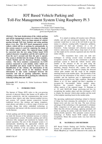
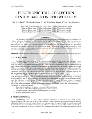
Vol-2 Issue-2 2016IJARIIE-ISSN(O)-2395-4396amount of second toll gate rotate in anticlockwise direction and gate will be close. After crossing vehicle, thecounter will be increase by one and result will be display on LCD.LCDDISPLAYGSM MODULEARM 7(LPC2148)RS232GATE ASSEMBLYDC MOTORBUZZERIR SENSOR5V POWER SUPPLYRFIDREADERFigure 1. Block Diagram3.1 RFID Technology3.1.1 RFID (Radio Frequency Identification)1.2.3.RFID is an automatic identification method, relying on storing and slightly retrieving data using procedurecalled RFID tags or transponders.The technology requires some extent of co-operation of an RFID reader and an RFID tag.An RFID tag is an object that can be applied to a product, animal, or person for the tracking andidentification using radio waves. Some tags have reading capacity to few meters away from the line of sightof the reader.3.1.2 RFID TAGAn RFID tag is a microchip collective by means of an antenna inside a compressed package; the packagingis structured to agree to the RFID tag chosen attached to an object to be tracked. "RFID" stands for Radio FrequencyIdentification. The tag's antenna picks up signals since an RFID reader or scanner and after that returns the signal,usually with some additional data (like a single serial number or other customized information). RFID tags can bevery small - the size of a big rice particle. Others may be the size of a small paper back book.3.1.3 PASSIVE RFID TAGPassive tags i.e. RFID tag does not include a battery, the power is supplied via the reader. While radiowaves since the reader be encountered by a passive RFID tag, the coiled antenna inside the tag form a magneticfield. The tag draws power from system to stimulate the given circuit. The tag then sends the informationdetermined in the tag's memory.1874www.ijariie.com839
Vol-2 Issue-2 2016IJARIIE-ISSN(O)-2395-43963.1.4 ANTENNA (RFID TAG ANTENNA)The antenna in an RFID tag permits the tag to replace data by using the reader. Passive RFID tags usecoiled antenna that can create a magnetic field provided through the reader's carrier indication energy generation.3.2. IR SensorThe IR Transmitter Receiver gate is used our project to identify the accurate location &place of the vehicleon the weight cell laminate Because one problem with weight cell plate is that it is unable to weight the affectingobject. The IR transmitter emits the IR rays towards the IR receiver. As the vehicle arrives diagonally the gate therays are deflected since the vehicle & IR receiver doesn’t get several signals. The IR Receiver self-control give thereplying signal to the control device to actuate the load cell laminate as the vehicle is at accurate position on theweight cell plate. At this time for IR transmitter we are using IR LED’s. The IR transmitter we can design in ourhome by immediately connecting desired rate of resistance in POSITIVE ARM& additional is grounded.The IR receiver have three pins i.e. 5V supply, GND. Line, signal line.3.3. DC MotorsA DC motor is an electrical motor that runs on electrical energy (DC) electricity. In any motor, operation ispredicated on easy electromagnetism. A current-carrying conductor generates a force field; once this can be thenplaced in associate degree external magnetic field, it'll expertise a force proportional to this within the conductor,and to the strength of the external force field. As yo u're cognizant of from wiggling with magnets as a child,opposite (North and South) polarities attract, whereas like polarities (North and North, South and South) repel. theinterior configuration of a DC motors designed to harness the magnetic interaction between a current-carryingconductor associate degreed an external force field to come up with movement motion. Speed dominant of DCmotors DC motor speed controllers ar very- helpful for dominant the motion of robotic and industrial automationsystems.3.4. GSM MODEMGlobal System for Mobile communication is a digital mobile telecom system. With the assistance of GSMmodule interfaced, we will send short text messages to the specified authorities as per the apply ing. GSM module isprovided by SIM uses the mobile service supplier and send SMS to the several authorities as per programmed. Thistechnology changes the system a wireless system with no specific vary limits.GSM uses a variation of your time division multiple access from the given 3 digital wireless telecomtechnologies (TDMA, GSM, and CDMA). GSM compresses and digitizes the given information and then sends itdown a channel with 2 alternative streams of user knowledge, every in its own slot. It can operate at either 900 or1800 megacycle per second waveband.3.5. Liquid Crystal Displayi) Tthe foremost unremarkably used alphanumerical displays area unit 1x16 (Single Line & sixteen characters),2x16 (Double Line & sixteen character per line) &4x20 (four lines & Twenty characte rs per line).ii) The liquid crystal display needs three management lines (RS, R/W & EN) & eight (or 4) knowledgelines. the amount on knowledge lines depends on the mode of operation. If operated in eight -bit mode then 8knowledge lines three management lines i.e. total eleven lines area unit needed. And if operated in four-bit modethen 4 knowledge lines three management lines i.e. seven lines area unit needed. However will we decide thatmode to use? It’s easy if you've got spare knowledge lines you'll be able to choose eight bit mode &. If there's atime constrain i.e. show ought to be quicker than we've got to use 8-bit mode as a result of primarily 4-bit modetakes double as longer as compared to 8-bit mode.iii) Once RS is low (0), the info is to be treated as a command. once RS is high (1), {the knowledge information}being sent is taken into account as text data that ought to be displayed on the screen.iv). Once R/W is low i.e. 0, the data on the info bus is being written to the liq uid crystal display. R/W is high i.e. 1,the program is effectively reading from the liquid crystal display. Most of the days there's no ought to browse fromthe liquid crystal display thus this line will directly be connected to Ground so saving one controller line.1874www.ijariie.com840
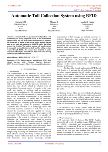
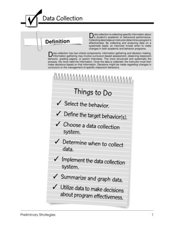
Vol-2 Issue-2 2016IJARIIE-ISSN(O)-2395-4396v). The change pin is employed to latch the info gift on the info pins. A HIGH - LOW signal is needed to latch theinfo. The liquid crystal display interprets and executes our command at the moment the nut line is brought low. Ifyou ne'er bring nut low, your instruction can ne'er be dead4. SOFTWARE DESIGN: In this system small ’C complete is employed to develop the program for ARM7 processor. Theprogramming is completed by victimization in Embedded C language. The compiler used here is ANSI C as aresults of it's best resolution for developing code for PIC devices conjointly these area unit user friendly and a priceeffective tool for all embedded C comes. This selections is a spontaneous IDE powerful compiler with advanceversion. It having voluminous package and hardware libraries with further tools can assist you in your work4.1 ALGORITHM:1.2.3.4.5.6.7.8.9.10.Start.Initialize GSM , RFID,IR Sensor.Check for presence of car.If affirmative then deduct certain quantity from user account via RFID.Open gate via motor assemble.Count are increase by one and show on liquid crystal display.Send SMS to the user of the group action.Closed gate .If NO gate won't open.End.4.2 RESULTThe given below figure a shows the final output on LCD display . Where as the figure b shows the messageon mobile screen of owners vehicle.Fig A. Transmitter And Receiver And GSM Switching Systems.1874www.ijariie.com841
Vol-2 Issue-2 2016IJARIIE-ISSN(O)-2395-4396Fig B. Transmitter And Receiver And GSM Switching Systems4.3 APPLICATION1.2.3.4.5.6.7.8.Machine-drive vehicle identification.Machine-drivenvehicle classification.Group action processing (Toll calculation).Is accustomed trace the vehicle if this technique is centralized.Parking system.CONCLUSIONReducing the personnel needed for assortment of cash at the tract. scale back the traffic indirectly leadingto reduction of your time at the tract.RFID tag & reader, that in coordination with one another may be wont tosight the vehicle identity. Trans receiver is employed for sleuthing the presence of the vehicle at totally differentlocations which is able to act because the gate pass to the toll plaza[1].REFERENCES1. S. Nandhini, P. Premkumar, Automatic Toll Gate System victimisation Advanced RFID and GSM Technology.,International Journal of Advanced analysis in Electrical Electronicsand Instrumentation Engineering.2. Janani S P, Meena S., Automatized Toll Gate System victimisation Passive RFID and GSM Technology., Journalof laptop Applications ISSN: 0974 – 1925, Volume-5, Issue EICA2012-3, February ten, 2012.3. Rakhi Kalantri, Anand Parekar, Akshay Mohite, Rohan Kankapurkar, RFID primarily based Toll assortmentSystem., Rakhi Kalantri et al, / (IJCSIT) International Journal of technology and data Technologies, Vol. 5 (2) ,2014, 2582-2585.4. Anish Dhurat, Parag Magal, Manish Chheda, Darshan Ingle, Gateless Electronic Toll assortment victimisationRFID, IOSR Journal of laptop Engineering (IOSR-JCE) e-ISSN: 2278-0661, p- ISSN: 2278-8727Volume sixteen,Issue 2, Ver. VI (Mar-Apr. 2014), PP 73-80 WWW.iosrjournals.org.5. T. Arun Prasath, M.S.Dhanabal, Automatic Toll Gate System victimisation RFID And GSM Technology,International Journal of Science and analysis (IJSR) ISSN (Online): 2319-7064 Index Copernicus worth (2013):half-dozen.14 Impact issue (2013): four.4386. Yvan Duroc and Darine Kaddour, Yvan Duroc and Darine Kaddour, LCIS - metropolis INP, 50 rue B. Americanstate Laffemas, 26000 Valence, France1874www.ijariie.com842
Vol-2 Issue-2 2016IJARIIE-ISSN(O)-2395-43967. Khadijah Kamarulazizi, Dr.WidadIsmail(2011), “Electronic Toll assortment System Using Passive RFIDTechnology”.Journal Of Theoretical And Applied data Technology.8. Minghe Yu, Dapeng Zhang, Yurong Cheng ,Mingshun Wang “ AN RFID Electronic Tag primarily basedAutomatic Vehicle Identification System For Traffic Iot Applications”. Control and call Conference (CCDC), 2011Chinese.9. ChonghuaLi ,“Automatic Vehicle Identification System supported RFID” .Anti-Counterfeiting Security andIdentification In Communication, 2010.10. Unified Electronic Toll assortment Technology For National Highways In Asian nation, The Ministry Of RoadTransport And route Vide Order No:Nh 12037/33/2010-Pic.11. Yanpeng Sun, Yuan Zhang, PengPeng,” style and Realization of two 45ghz Active RFID System”. SecondInternational Conference on Intelligent Computation Technology and Automation,2009.1874www.ijariie.com843
The use of prepaid toll statements (no need to request for receipts) 4. Lowered toll collection costs[3]. 2. PROPOSED SYSTEM:- The RFID tag is used to access vehicle information with unique id mounted on each vehicle contains several information. The tag is read by RFID reader placed at toll gate. when the vehicle pass to toll gate IR sensor