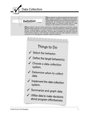
Transcription
Page 1AUTOMATED TOLL COLLECTIONSYSTEM USING RFIDbyNameRoll No.KHUSBOO SINGH11700314048PURBAYAN SAHA11700314063CHITRANIVAKARMAKARSOUVIK KUMARDUTTA1170031403411700314108Registration 51411701102902015of 2014of 2014of 2014of 2014-A comprehensive project report has been submitted in partial fulfillment ofthe requirements for the degree ofBachelor of TechnologyinELECTRONICS & COMMUNICATION ENGINEERINGUnder the supervision ofMrs. Saraswati SahaAssociate ProfessorDepartment of Electronics & Communication EngineeringRCC INSTITUTE OF INFORMATION TECHNOLOGYAffiliated to Maulana Abul Kalam Azad University of Technology, WestBengalCANAL SOUTH ROAD, BELIAGHATA, KOLKATA – 700015MAY, 2018
Page 2CERTIFICATE OF APPROVALThis is to certify that the project titled “AUTOMATED TOLL COLLECTIONSYSTEM USING RFID” carried out byNameRoll No.KHUSBOO SINGH11700314048PURBAYAN SAHA11700314063CHITRANIVAKARMAKARSOUVIK KUMARDUTTA1170031403411700314108Registration 51411701102902015of 2014of 2014of 2014of 2014-for the partial fulfillment of the requirements for B.Tech degree in Electronics andCommunication Engineering from Maulana Abul Kalam Azad University ofTechnology, West Bengal is absolutely based on his own work under thesupervision of Mrs. Saraswati Saha. The contents of this thesis, in full or in parts,have not been submitted to any other Institute or University for the award of anydegree or diploma.Dr. Abhishek BasuHead of the Department (ECE)RCC Institute of Information Technology.Mrs. Saraswati SahaProfessor , Dept. of ECERCC Institute of Information Technology
Page 3DECLARATION“We do hereby declare that this submission is our own work conformed tothe norms and guidelines given in the Ethical Code of Conduct of the Institute andthat, to the best of our knowledge and belief, it contains no material previouslywritten by another neither person nor material (data, theoretical analysis, figures,and text) which has been accepted for the award of any other degree or diploma ofthe university or other institute of higher learning, except where dueacknowledgement has been made in the text.”.Khusboo Singh141170110230 of2014-2015Roll No: 11700314048Registration No:.Chitraniva Karmakar141170110216 of2014-2015Roll No: 11700314034Registration No:Date:Place:Purbayan Saha141170110245 of2014-2015Roll No: 11700314063Registration No:.Souvik Kumar Dutta141170110290 of2014-2015Roll No: 11700314108Registration No:
Page 4CERTIFICATE of ACCEPTANCEThis is to certify that the project titled “AUTOMATED TOLL COLLECTIONSYSTEM USING RFID” carried out byNameRoll No.KHUSBOO SINGH11700314048PURBAYAN SAHA11700314063CHITRANIVAKARMAKARSOUVIK KUMARDUTTA1170031403411700314108Registration 51411701102902015of 2014of 2014of 2014of 2014-is hereby recommended to be accepted for the partial fulfillment of the requirementsfor B.Tech degree in Electronics and Communication Engineering from Maulana AbulKalam Azad University of Technology, West BengalName of the Examiner Signature with Date:1. .2. . .3. . 4. .
Page 5ABSTRACTATCS is an Automated Toll Collection System used for collecting tax automatically. In thiswe do the identification with the help of radio frequency. A vehicle will hold an RFID tag.This tag is nothing but unique identification number assigned. This will be assigned by RTOor traffic governing authority. In accordance with this number we will store, all basicinformation as well as the amount he has paid in advance for the TOLL collection. Readerwill be strategically placed at toll collection center. Whenever the vehicle passes the tollcollection center, the tax amount will be deducted from his prepaid balance. New balancewill be updated. In case if one has insufficient balance, his updated balance will be negativeone. To tackle this problem, we are alarming a sound, which will alert the authority that thisvehicle doesn’t have sufficient balance and that particular vehicle can be trapped. Asvehicles don’t have to stop in a queue, it assures time saving, fuel conservation and alsocontributing in saving of money. Automatic Toll Collection systems have really helped a lotin reducing the heavy congestion caused in the metropolitan cities of today. It is one of theeasiest methods used to organize the heavy flow of traffic.
Page 6CONTENTSTITLE PAGE 1CERTIFICATE OF APPROVAL . 2DECLARATION . 3CERTIFICATE OF ACCEPTANCE . 4ABSTRACT . 5CONTENTS . 6LIST OF FIGURES . 7LIST OF TABLES 8INTRODUCTION . 9PROBLEM DEFINITION . 10PROBLEM STATEMENT . 11SCOPE OF THE PROJECT . 13EQUIPMENTS REQUIRED 14METHODOLOGY 26FUTURE SCOPE OF THE PROJECT . 30CONCLUSION . 31REFERENCE . 32
Page 7LIST OF FIGURESSl no.Name of figurePage no.Fig 1Practical overview of the system12Fig 2Pin diagram of Atmega 328P Microcontroller14Fig 3Arduino Uno (Atmega 328P Microcontroller)15Fig 4MFRC522 RFID Module17Fig 5.iDS 130719Fig 5.iiCircuit Diagram19Fig 6.iLCD Screen20Fig 6.iiLCD Screen20Fig 6.iiiPin diagram of LCD20Fig 7Pin diagram of L293D22Fig 8IR LED23Fig 9IR Receiver TSOP173823Fig 10IR Transmitter Circuit Diagram24Fig 11IR Receiver Circuit Diagram25Fig 12Flow Chart of system implementation26Fig 13Arduino to LCD display connection27Fig 14Arduino to RFID Module connection27Fig 15Pin diagram of the complete system28
Page 8LIST OF TABLESSl no.Name of tablePage no.Table 1Pin description of LCD21
Page 9INTRODUCTIONAs we all know that transportation is the backbone of any country’s economy. Improvementin transportation systems result into the good lifestyle in which we achieve extraordinaryfreedom for movement, immense trade in manufactured goods and services, as well ashigher rate of employment levels and social mobility. In fact, the economic condition of anation has been closely related to efficient ways of transportation. Increasing number ofvehicles on the road, result into number of problems such as congestion, accident rate, airpollution and many other . All economic activities for different tasks use different methodsof transportation. For this reason, increasing transportation is an immediate impact onproductivity of nation and the economy. Reducing the cost of transporting resource atproduction sites and transport completed goods to markets is one of the important keyfactors in economic competition. Automatic toll collection is a technology allows theautomated electronic collection of toll costs. As it is studied by researchers and also appliedin various expressways, bridges, and tunnels require such a process of Automatic Toll Plaza.ATP is capable of determining if the vehicle is registered or not, and then informing themanagement center about to process violations, debits, and participating accounts .The mostexcellent advantage of this ATP system is that it is capable of eliminate congestion in tollplaza, especially during those seasons when traffic seems to be higher than normal.The Benefits of this System are: Shorter queues at toll plazas by increasing toll booth service rates Faster and more efficient service The ability to make payments by keeping abalance on the card itself and The use of postpaid toll statements Other general advantages include minimization of fuel wastage and reduced emissions byreducing deceleration rate, waiting time of vehicles in queue, and acceleration.For Toll Operators, the benefits include: Lowered toll collection costs Better audit control by centralized user account Expanded capacity without building more infrastructures.Thus, the ATP system is useful for both the motorists and toll operators, this is the reason ofextended use of ATP system throughout the world.
P a g e 10PROBLEM DEFINITIONThe base idea behind implementing RFID Based Toll System is to automate the tollcollection process and their by reducing manual operation in toll booths and the long queuesat toll booths using RFID tags installed on the vehicles. In addition to we can not only helpthe vehicle owners and system administrators from vehicle theft detection but also can trackover speeding vehicles, and crossing the signals. Here we are going to see some pointsregarding to purpose behind choosing this topic & what is the requirement of this type ofthe project in our day to day life. Automatic collection of toll tax. Free flow of traffic. Time saving. Record maintenance. Problems with pursuing toll evaders. Avoid the fuel loss. Saving of time in collecting toll. Avoid financial loss. To monitor the traffic.According to the survey of Karnataka Government, in Sept.2012 they have proposed to getthe annual toll collection about 2500 crores/year .But in the present situation they are able tocollect only 900 crores of the toll value. Means there is loss of 600 crores due to humanerrors. So, in this situation we have to control this leakage. Now the present system we havewith us on the high ways takes 1 minute to complete the toll collection process for onevehicle. With this automatic process, it will take just less than a minute. to complete thewhole process. As there is reduction in time for completion of the process so indirectly therewill be no traffic as such & as there is no traffic so no fuel wastage takes place & the purposeof designing the highways is achieved i.e. reduction in journey time & also the money losswill be reduced.
P a g e 11PROBLEM STATEMENTWhenever the matter of Integration of systems comes to mind, we think of a system havingthe following important features viz.Accuracy: All the functionally bonded logical dependencies must be integrated.Efficiency: The whole system should work under all circumstances and on a long run itshould work efficiently irrespective of their proprietary format.Cost Effectiveness: As our software do not require any special software for implementationhence is less costly as compared to other existing system.Any Prerequisite for the use: As the existing systems are not altered, and integration isdone at the background hence there is no need for any training.BACKGROUND OVERVIEWA. Existing System:There are two methods of collecting tax presently used they are First is the traditionalmanual method where one person collects money and issues a receipt. The other one is theSmart Card method where the person needs to show the smart card to the system installedat the toll tax department to open the Gate.B. Drawbacks of Existing System:Both the above mentioned method for collecting tax is time consuming method. Chances ofescaping the payment of tax are there. It leads to queuing up of following vehicles.C. History of Automatic Toll Tax:Design and development of a “RFID Based Automatic Toll Plaza” which is based onmicrocontroller, RFID technology and load cell to save the time at toll plaza and havingcashless operation As the name implies “RFID Based Automatic Toll Plaza” the key theme ofour project is the automation. So here we will just take the overlook of what is mean byAutomation. In simple words the Automation means the human being from the processwith the machines. Before going further we just take the overlook of history of the tollplazas. So before the 90’s decade the toll plazas were fully manual controlled. Means thereare total four people for operating the Toll gate in this two people will be used for opening &closing of the gate & another two are for reception of the money & data keeping etc.Semi Automatic Toll plazas were launched after the introduction of Express ways in 1995, inwhich data is stored in computers and gate operation is automatic, only two personals arerequired for single booth. But here we are going to see the human less toll plaza. Activewave Inc has currently deployed a system of active tag vehicle monitoring solution. Activewave vehicle products have a range of 30 meters and operate in the 916 – 927 MHz for thetransmit operations and 433 MHz for the receive link. Active wave products are currentlyequipped with 256 Kbits of fixed memory. The tag is powered with a replaceable 3V battery
P a g e 12and the total weight is 14 grams. Elementary signals are shown with the help of blinkingLEDs and beeping sounds. Smart key Access Control Systems have a client – server modelbased system with an SQL server handling multiple vehicle monitoring systems. They havedesigned a user interface using the Microsoft .NET Framework. Smart key also operate inthe 900MHz band but have a small range of 30 meters. RFID based toll collection systemuses active RFID tag which uses car battery power. The implementation is divided into thedesign of two modules- the Vehicle Module (Active Tag) and the Base Module. The twomodules communicate via RF modem connected to each module.PROPOSED SYSTEMThis project gives the simplified procedure to passengers to pay toll at toll booths by makingthem automated, vehicle theft detection, signal breaking avoidance, tracking over speedvehicles. All these activities are carried using single RFID tag thus saving the efforts ofcarrying money and records manually.A. Automatic Toll Collection: The RFID Readers mounted at toll booth will read theprepaid RFID tags fixed on vehicles’ windshield and automatically respective amount willbe deducted. If the tag is removed from the windshield then cameras fixed at two sites at tollplaza take snaps of the front and back number plate. Since every vehicle registration ID islinked to users account, toll can be deducted from the account bank directly.B. Vehicle Theft Detection: When vehicle is stolen the owner registers complaint on thewebsite with its registration ID and unique RFID tag number. Now when stolen vehiclepasses by the toll plaza, the tag fixed on it is matched with the stolen vehicle's tag in thedatabase at the toll booth.C. Signal Breaking Avoidance: The vehicle ignoring the traffic signal will be detected by theRFID readers fixed at signal crossing and will be notified to the traffic police. This can bedone efficiently and great accuracy.D. Tracking Over speeding Vehicle: Vehicle travelling above speed limit can be trackedwith 100 % accuracy.
P a g e 13SCOPE OF THE PROJECTWhenever the matter of Integration of systems comes to mind, we think of a system havingthe following important features viz.Accuracy: All the functionally bonded logical dependencies must be integrated.Efficiency: The whole system should work under all circumstances and on a long run itshould work efficiently irrespective of their proprietary format.Cost Effectiveness: As our software do not require any special software for implementationhence is less costly as compared to other existing system.Any Prerequisite for the use: As the existing systems are not altered, and integration isdone at the background hence there is no need for any training.Flexibility of implementationThe main power of ATCS is the technology which is used, that is the RADIO FREQUENCYIDENTIFICATION. The basic power of this technology is that it’s very flexible. Even withthe slightest of change in ATCS, the product can be shaped into a completely differentimplementation and all that can be because RFID is independent of every other hardwarethat can be used to boost up the system’s performance.RADIO FREQUENCY has vast implementation areas in medical, defence and many latestproducts that are being developed is based on RFID solution. The main areas is animaltracking, human implants, vehicle tracking, speed tracking, physical implementation.Following are the features and advancement of ATCS over presently existing system:[1] RFID tag cannot be cloned, so cannot be cheated.[2] Very efficient saving of time.[3] Wastage of money reduced.[4] Consumption of oil is reduced.[5] Pollution is reduced to a large extent.[6] Speedy transport.[7] Less congestion on the roadways.[8] Comparatively less maintenance cost
P a g e 14EQUIPMENTS REQUIRED: Arduino Uno (Atmega 328P Microcontroller)MFRC522 RFID ModuleLCD 16X2SwitchRTC DS1307Motor Driver L293DIR Obstacle SensorAtmega 328P Microcontroller:It has 14 digital input/output pins (of which 6 can be used as PWM outputs), 6 analoginputs, a 16 MHz ceramic resonator, a USB connection, a power jack, an ICSP header, and areset button. It contains everything needed to support the microcontroller; simply connect itto a computer with a USB cable or power it with a AC-to-DC adapter or battery to getstarted.FIGURE 2: Pin diagram of Atmega 328P Microcontroller
P a g e 15FIGURE 3: Arduino Uno(Atmega 328P Microcontroller)Specifications: Microcontroller ATmega328 Operating Voltage 5V Input Voltage (recommended) 7-12V Digital I/O Pins 14 (of which 6 provide PWM output) Analog Input Pins 6 DC Current per I/O Pin 40 mA DC Current for 3.3V Pin 50 mA Flash Memory 32 KB of which 0.5 KB used by boot loader SRAM 2 KB EEPROM 1 KB Clock Speed 16 MHzThe power pins are as follows: VIN. The input voltage to the Arduino board when it's using an external power source (asopposed to 5 volts from the USB connection or other regulated power source). We cansupply voltage through this pin, or, if supplying voltage via the power jack, access itthrough this pin. The regulated power supply used to power the microcontroller and other components onthe board. This can come either from VIN via an on-board regulator, or be supplied by USBor another regulated 5V supply. A 3.3 volt supply generated by the on-board regulator. Maximum current draw is 50 mA. GND. Ground pins.Input Output Pins: Serial: 0 (RX) and 1 (TX). Used to receive (RX) and transmit (TX) TTL serial data.These pins are connected to the corresponding pins of the ATmega8U2 USB-to-TTLSerial chip.
P a g e 16 External Interrupts: 2 and 3. These pins can be configured to trigger an interrupt ona low value, a rising or falling edge, or a change in value. See the attachInterrupt()function for details.PWM: 3, 5, 6, 9, 10, and 11. Provide 8-bit PWM output with the analogWrite()function.SPI: 10 (SS), 11 (MOSI), 12 (MISO), 13 (SCK). These pins support SPI communication,which, although provided by the underlying hardware, is not currently included inthe Arduino language.LED: 13. There is a built-in LED connected to digital pin 13. When the pin is HIGHvalue, the LED is on, when the pin is LOW, it's off.The Uno has 6 analog inputs, each of which provides 10 bits of resolution (i.e. 1024different values). By default they measure from ground to 5 volts, though is itpossible to change the upper end of their range using the AREF pin and theanalogReference() function. Additionally, some pins have specialized functionality:I 2C: 4 (SDA) and 5 (SCL). Support I2C communication using the Wire library. Thereare a couple of other pins on the board:AREF. Reference voltage for the analog inputs. Used with analog Reference().Reset. Bring this line LOW to reset the microcontroller.MFRC522 RFID Module:Mifare RC522 is the high integrated RFID card reader which works on non-contact 13.56MHz communication, is designed by NXP as low power consumption, low cost and compactsize read and write chip, is the best choice in the development of smart meters and portablehand-held devices.MF RC522 use the advanced modulation system, fully integrated at 13.56MHz with all kindsof positive non-contact communication protocols. Support 14443A compatible answersignal. DSP deal with ISO14443A frames and error correction. Furthermore, it also supportsrapid CRYPTO1 encryption to validate Mifare series products. MFRC522 support Mifareseries higher speed non-contact communication, duplex communication speed up to 424kb/s. As a new family member in 13.56MHz RFID family, MF RC522 has many similarities toMF RC5200 and MF RC530, and also has more new features.This module can fit directly in hand held devices for mass production. Module use 3.3Vpower supply, and can communicate directly with any CPU board by connecting throughSPI protocol, which ensure reliable work, good reading distance.Specifications Voltage: DC 3.3V Operating Current :13-26mA Idle Current :10-13mA Sleep current: 80uA Peak current: 30mA
P a g e 17 Operating Frequency: 13.56MHzSupported card types: mifare1 S50, mifare1 S70, mifare UltraLight, mifare Pro, mifareDesfireDimensions: 40mm 60mmModule Interface SPI Data Transfer Rate: Max. 10Mbit/sCard reading distance :0 30mm (Mifare1 card)RFID Technology:The RFID reader is one kind of wireless module used for transferring the data to identifyand track tags which are connected to objects. The RFID tag mainly includes the storedinformation. Some of the RFID tags are run by electromagnetic induction from magneticfields formed nearby the reader. RFID reader comprises an RF module that works as atransmitter as well as a receiver of RF (radio frequency) signals.The TX of the RF module is inbuilt with an oscillator to make the carrier frequency. Amodulator to intrude commands upon this carrier signal and an amplifier to raise the signalsample to wake the tag. The RX (receiver) of the RFID module contains a demodulator toremove the returned information and also grips an amplifier for supporting the signal ofprocessing. A microprocessor is used for forming the control unit, which uses an operatingsystem, a memory of the module filter and also stores the data.What are Real Time Clocks?Real time clocks (RTC), as the name recommends are clock modules. The DS1307 real timeclock (RTC) IC is an 8 pin device using an I2C interface. The DS1307 is a low-powerclock/calendar with 56 bytes of battery backup SRAM. The clock/calendar provides seconds,
P a g e 18minutes, hours, day, date, month and year qualified data. The end date of each month isautomatically adjusted, especially for months with less than 31 days.They are available as integrated circuits (ICs) and supervise timing like a clock and alsooperate date like a calendar. The main advantage of RTC is that they have an arrangement ofbattery backup which keeps the clock/calendar running even if there is power failure. Anexceptionally little current is required for keeping the RTC animated. We can find theseRTCs in many applications like embedded systems and computer mother boards, etc. In thisarticle we are going to see about one of the real time clock (RTC), i.e. DS1307.Pin Description of DS1307:Pin 1, 2: Connections for standard 32.768 kHz quartz crystal. The internal oscillator circuitryis intended for operation with a crystal having a specified load capacitance of 12.5pF. X1 isthe input to the oscillator and can alternatively be connected to an external 32.768 kHzoscillator. The output of the internal oscillator, X2 is drifted if an external oscillator isconnected to X1.Pin 3: Battery input for any standard 3V lithium cell or other energy source. Battery voltageshould be between 2V and 3.5V for suitable operation. The nominal write protect trip pointvoltage at which access to the RTC and user RAM is denied is set by the internal circuitry as1.25 x VBAT nominal. A lithium battery with 48mAhr or greater will backup the DS1307 formore than 10 years in the absence of power at 25ºC. UL recognized to ensure against reversecharging current when utilized as a part of conjunction with a lithium battery.Pin 4: Ground.Pin 5: Serial data input/output. The input/output for the I2C serial interface is the SDA,which is open drain and requires a pull up resistor, allowing a pull up voltage upto 5.5V.Regardless of the voltage on VCC.Pin 6: Serial clock input. It is the I2C interface clock input and is used in datasynchronization.Pin 7: Square wave/output driver. When enabled, the SQWE bit set to 1, the SQW/OUT pinoutputs one of four square-wave frequencies (1Hz, 4 kHz, 8 kHz, and 32 kHz). This is alsoopen drain and requires an external pull-up resistor. It requires application of either Vcc orVb at to operate SQW/OUT, with an allowable pull up voltage of 5.5V and can be leftfloating, if not used.Pin 8: Primary power supply. When voltage is applied within normal limits, the device isfully accessible and data can be written and read. When a backup supply is connected to thedevice and VCC is below VTP, read and writes are inhibited. However at low voltages, thetimekeeping function still functions.Features: Programmable square wave output signal Automatic power-fail detect and switch circuitry
P a g e 19 Consumes less than 500nA in battery backup mode with oscillator runningAvailable in 8-pin DIP or SOICUnderwriters Laboratory (UL) recognizedReal-time clock (RTC) counts seconds, minutes, hours, date of the month, month, dayof the week, and year with leap-year compensation valid up to 210056-byte non-volatile RAM for data storageTwo-wire interface (I2C)Using the DS1307 is primarily written to and read the registers of this chip. The memorycontains all 64 DS1307 8-bit registers are addressed from 0 to 63 (from 00H to 3FH thehexadecimal system). The first eight registers are used for the clock register the remaining 56vacant can be used as RAM contains temporary variable if desired. The first seven registerscontain information about the time of the clock including: seconds, minutes, hours,secondary, date, month and year. The DS1307 include several components such as powercircuits, oscillator circuits, logic controller and I2C interface circuit and the address pointerregister (or RAM). Let’s see the working of DS1307.Working of DS1307:In the simple circuit the two inputs X1 and X2 are connected to a 32.768 kHz crystaloscillator as the source for the chip. VBAT is connected to positive culture of a 3V batterychip. Vcc power to the I2C interface is 5V and can be given using microcontrollers. If thepower supply Vcc is not granted read and writes are inhibited. START and STOP conditionsare required when a device wants to establish communication with a device in the I2Cnetwork.FIGURE 5: i) DS1307ii) Circuit Diagram
P a g e 20Liquid Crystal Display(LCD):Liquid crystal displays (LCDs) have materials which combine the properties of both liquidsand crystals. An LCD consists of two glass panels, with the liquid crystal material sandwitched in between them. The inner surface of the glass plates are coated with transparentelectrodes which define the character, symbols or patterns to be displayed polymeric layersare present in between the electrodes and the liquid crystal, which makes the liquid crystalmolecules to maintain a defined orientation angle.FIGURE 6: i) & ii) LCD ScreenFIGURE 6: iii) Pin diagram of LCD
P a g e 21Pin Description:Pin NoFunction1Ground (0V)2Supply voltage; 5V (4.7V – 5.3V)3Contrast adjustment; through a variable resistor45678910111213141516Selects command register when low; and data register whenhighLow to write to the register; High to read from the registerSends data to data pins when a high to low pulse is given8-bit data pinsBacklight VCC (5V)Backlight Ground (0V)NameGroundVccVEERegister SelectRead/writeEnableDB0DB1DB2DB3DB4DB5DB6DB7Led Led-In this project we will be constructing a simplest RFID based attendance system which doesnot overcomplicate the project.In this project we will be using RTC module, which is utilized for enabling and disabling theattendance system within a given time period, so that we can keep the late comers at bay.The RFID module “RFID-RC522” which can do read and write operations on NXP basedRFID tags. NXP is lead producer of RFID tags in the world and we can get them on onlineand offline stores easily. A 16 x 2 LCD display is used, which is to showcase informationsuch as time, date, number of attendance, etc. And finally an Arduino board is utilizedwhich is the brain of the project.DC Motor Driver:L293D is a dual H-Bridge motor driver, so with one IC we can interface two DC motorswhich can be controlled in both clockwise and counter clockwise direction we can controlspeed of each dc motor by giving PWM to enable pin .L293D has output current of 600mAand peak output current of 1.2A per channel. Moreover for protection of circuit from backEMF output diodes are included within the IC. The output supply (VCC2) has a wide rangefrom 4.5V to 36V, which has made L293D a best choice for DC motor driver.As we can see in the circuit, three pins are needed for interfacing a DC motor (A, B, Enable).If we want to control speed enable pin is connected to the PWM pin of microcontroller. Wehave connected only one motor and used the enable pin to control the speed of dc motor.
P a g e 22FIGURE 7: Pin diagram of L293DL293D Logic Table:Let’s consider a Motor connected on left side output pins (pin 3, 6). For rotating the motor inclockwise direction the input pins has to be provided with Logic 1 and Logic 0. Pin 2 Logic 1 and Pin 7 Logic 0 Clockwise Direction Pin 2 Logic 0 and Pin 7 Logic 1 Anticlockwise Direction Pin 2 Logic 0 and Pin 7 Logic 0 Idle *No rotation *Hi-Impedance state] Pin 2 Logic 1 and Pin 7 Logic 1 Idle *No rotation In a very similar way the motor can also operate across input pin 15,10 for motor on theright hand s
closing of the gate & another two are for reception of the money & data keeping etc. Semi Automatic Toll plazas were launched after the introduction of Express ways in 1995, in which data is stored in computers and gate operation is automatic, only two personals are required for single booth. But here we are going to see the human less toll plaza.