Transcription
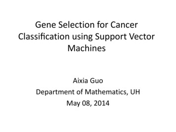
SiA413ADJwww.vishay.comVishay SiliconixP-Channel 12 V (D-S) MOSFETFEATURESPowerPAK SC-70-6L SingleS4D5 TrenchFET power MOSFETD6 Thermally enhanced PowerPAK SC-70 package- Small footprint area- Low on-resistance052.S7mm152.0Top Viewmm23DGBottom View Material categorization: for definitions ofcompliance please see www.vishay.com/doc?999121DAPPLICATIONSMarking code: BSPRODUCT SUMMARYVDS (V)RDS(on) max. ( ) at VGS -4.5 VRDS(on) max. ( ) at VGS -2.5 VRDS(on) max. ( ) at VGS -1.8 VRDS(on) max. ( ) at VGS -1.5 VQg typ. (nC)ID (A) aConfigurationS Load switch, PA switch, and batteryswitch for portable devices -120.0290.0340.0440.10023-12SingleGDP-Channel MOSFETORDERING INFORMATIONPackagePowerPAK SC-70SiA413ADJ-T4-GE3SiA413ADJ-T1-GE3Lead (Pb)-free and halogen-freeABSOLUTE MAXIMUM RATINGS (TA 25 C, unless otherwise noted)PARAMETERDrain-source voltageGate-source voltageContinuous drain current (TJ 150 C)SYMBOLVDSVGSTC 25 CTC 70 CTA 25 CTA 70 CPulsed drain current (t 300 μs)Continuous source-drain diode currentMaximum power dissipationOperating junction and storage temperature rangeSoldering recommendations (peak temperature) d, eIDIDMTC 25 CTA 25 CTC 25 CTC 70 CTA 25 CTA 70 CISPDTJ, TstgLIMIT-12 8-12 a-12 a-10 b, c-8 b, c-40-12 a-2.9 b, c19123.5 b, c2.2 b, c-55 to 150260UNITVAW CTHERMAL RESISTANCE RATINGSPARAMETERSYMBOLTYPICALMAXIMUMUNITt 5sRthJA2836Maximum junction-to-ambient b, f C/WMaximum junction-to-case (drain)Steady stateRthJC5.36.5Notesa. Package limitedb. Surface mounted on 1" x 1" FR4 boardc. t 5 sd. See solder profile (www.vishay.com/doc?73257). The PowerPAK SC-70 is a leadless package. The end of the lead terminal is exposedcopper (not plated) as a result of the singulation process in manufacturing. A solder fillet at the exposed copper tip cannot be guaranteedand is not required to ensure adequate bottom side solder interconnectione. Rework conditions: manual soldering with a soldering iron is not recommended for leadless componentsf. Maximum under steady state conditions is 80 C/WS12-1141-Rev. B, 21-May-12Document Number: 636501For technical questions, contact: pmostechsupport@vishay.comTHIS DOCUMENT IS SUBJECT TO CHANGE WITHOUT NOTICE. THE PRODUCTS DESCRIBED HEREIN AND THIS DOCUMENTARE SUBJECT TO SPECIFIC DISCLAIMERS, SET FORTH AT www.vishay.com/doc?91000
SiA413ADJwww.vishay.comVishay SiliconixSPECIFICATIONS (TJ 25 C, unless otherwise noted)PARAMETERSYMBOLTEST CONDITIONSMIN.TYP.MAX.UNITVDSVGS 0 V, ID -250 μA-12---V-11--2.7-StaticDrain-source breakdown voltage VDS/TJVDS temperature coefficientVGS(th) temperature coefficient VGS(th)/TJID -250 μAGate-source threshold voltagemV/ CVGS(th)VDS VGS, ID -250 μA-0.4--1VGate-source leakageIGSSVDS 0 V, VGS 8 V-- 100nAZero gate voltage drain currentIDSSOn-state drain current aID(on)Drain-source on-state resistance aForward transconductance aRDS(on)gfsVDS -12 V, VGS 0 V---1VDS -12 V, VGS 0 V, TJ 55 C---10VDS -5 V, VGS -4.5 V-20--VGS -4.5 V, ID -6.7 A-0.0240.029VGS -2.5 V, ID -6.2 A-0.0280.034VGS -1.8 V, ID -2.3 A-0.0360.044VGS -1.5 V, ID -1 A-0.0500.100VDS -10 V, ID -6.7 A-30--1800--450--390--3857-2335-3-μAA SDynamic bInput capacitanceCissOutput capacitanceCossReverse transfer capacitanceCrssTotal gate chargeQgGate-source chargeQgsGate-drain chargeQgdGate resistanceRgTurn-on delay timeRise timeTurn-off delay timeFall timeTurn-on delay timeRise timeTurn-off delay timeFall timeVDS -10 V, VGS 0 V, f 1 MHzVDS -6 V, VGS -8 V, ID -10 AVDS -6 V, VGS -4.5 V, ID -10 A-6.5-f 1 MHz-7--2030VDD -6 V, RL 0.75 ,ID -8 A, VGEN -4.5 V, Rg 1 70105-4060trtd(off)VDD -6 V, RL 0.75 ,ID -8 A, VGEN -8 V, Rg 1 tfpFnC nsDrain-Source Body Diode CharacteristicsContinuous source-drain diode currentISPulse diode forward currentISMBody diode voltageVSDBody diode reverse recovery timetrrBody diode reverse recovery chargeQrrReverse recovery fall timetaReverse recovery rise timetbTC 25 CIS -8 A, VGS 0 VIF -8 A, di/dt 100 A/μs,TJ 25 a. Pulse test; pulse width 300 μs, duty cycle 2 %b. Guaranteed by design, not subject to production testing Stresses beyond those listed under “Absolute Maximum Ratings” may cause permanent damage to the device. These are stress ratings only, and functional operationof the device at these or any other conditions beyond those indicated in the operational sections of the specifications is not implied. Exposure to absolute maximumrating conditions for extended periods may affect device reliability.S12-1141-Rev. B, 21-May-12Document Number: 636502For technical questions, contact: pmostechsupport@vishay.comTHIS DOCUMENT IS SUBJECT TO CHANGE WITHOUT NOTICE. THE PRODUCTS DESCRIBED HEREIN AND THIS DOCUMENTARE SUBJECT TO SPECIFIC DISCLAIMERS, SET FORTH AT www.vishay.com/doc?91000
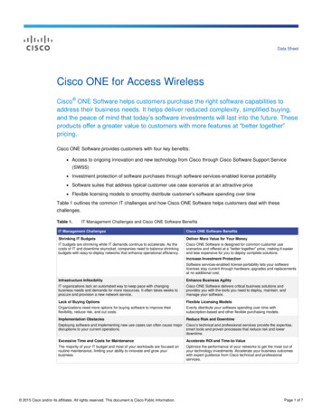
SiA413ADJwww.vishay.comVishay SiliconixTYPICAL CHARACTERISTICS (25 C, unless otherwise noted)4010VGS 5 thru 2.5 V8I D - Drain Current (A)I D - Drain Current (A)32VGS 2 V2416VGS 1.5 V864TC 25 C2TC 125 CVGS 1 V0.51.01.52.02.5TC - 55 C00.03.00.30.61.2VGS - Gate-to-Source Voltage (V)Output CharacteristicsTransfer Characteristics0.0830000.0725001.5Ciss0.060.05VGS 1.8 VVGS 2.5 V0.04VGS 4.5 V0.03200015001000CossCrss50000.02081624320403ID - Drain Current (A)6912VDS - Drain-to-Source Voltage (V)CapacitanceOn-Resistance vs. Drain Current and Gate Voltage1.28R DS(on) - On-Resistance (Normalized)ID 10 AVGS - Gate-to-Source Voltage (V)0.9VDS - Drain-to-Source Voltage (V)C - Capacitance (pF)R DS(on) - On-Resistance (Ω)00.06VDS 6 VVDS 9.6 V4200816243240ID 6.7 AVGS 4.5 V, 2.5 V1.1VGS 4.5 V, 2.5 V1.00.90.8- 50- 250255075100125Qg - Total Gate Charge (nC)TJ - Junction Temperature ( C)Gate ChargeOn-Resistance vs. Junction TemperatureS12-1141-Rev. B, 21-May-12150Document Number: 636503For technical questions, contact: pmostechsupport@vishay.comTHIS DOCUMENT IS SUBJECT TO CHANGE WITHOUT NOTICE. THE PRODUCTS DESCRIBED HEREIN AND THIS DOCUMENTARE SUBJECT TO SPECIFIC DISCLAIMERS, SET FORTH AT www.vishay.com/doc?91000
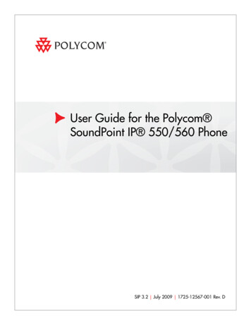
SiA413ADJwww.vishay.comVishay SiliconixTYPICAL CHARACTERISTICS (25 C, unless otherwise noted)1000.060TJ 150 CR DS(on) - On-Resistance (Ω)I S - Source Current (A)ID 6.7 ATJ 25 C1010.0480.036TA 125 C0.024TA 25 C0.01200.20.40.60.81.001.212345VGS - Gate-to-Source Voltage (V)VSD - Source-to-Drain Voltage (V)Source-Drain Diode Forward VoltageOn-Resistance vs. Gate-to-Source Voltage0.8300.725ID 250 µA20Power (W)V GS(th) (V)0.60.5150.4100.350.2- 50- 25025507510012500.001150TJ - Temperature ( C)0.010.11Time (s)101001000Threshold VoltageSingle Pulse Power, Junction-to-Ambient100Limited by R DS(on)*100 µsI D - Drain Current (A)101 ms10 ms1100 ms1s10 sTA 25 CSingle Pulse0.1DCBVDSS Limited0.010.1* VGS110100VDS - Drain-to-Source Voltage (V)minimum VGS at which RDS(on) is specifiedSafe Operating Area, Junction-to-AmbientS12-1141-Rev. B, 21-May-12Document Number: 636504For technical questions, contact: pmostechsupport@vishay.comTHIS DOCUMENT IS SUBJECT TO CHANGE WITHOUT NOTICE. THE PRODUCTS DESCRIBED HEREIN AND THIS DOCUMENTARE SUBJECT TO SPECIFIC DISCLAIMERS, SET FORTH AT www.vishay.com/doc?91000
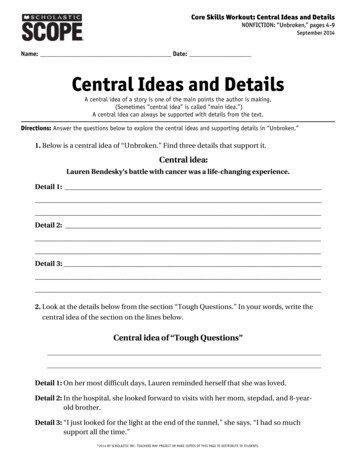
SiA413ADJwww.vishay.comVishay SiliconixTYPICAL CHARACTERISTICS (25 C, unless otherwise noted)3020Power Dissipation (W)ID - Drain Current (A)252015Package Limited10151055002550751001251500255075100TC - Case Temperature ( C)TC - Case Temperature ( C)Current Derating aPower Derating125150Notea. The power dissipation PD is based on TJ max. 150 C, using junction-to-case thermal resistance, and is more useful in settling the upperdissipation limit for cases where additional heatsinking is used. It is used to determine the current rating, when this rating falls below thepackage limitS12-1141-Rev. B, 21-May-12Document Number: 636505For technical questions, contact: pmostechsupport@vishay.comTHIS DOCUMENT IS SUBJECT TO CHANGE WITHOUT NOTICE. THE PRODUCTS DESCRIBED HEREIN AND THIS DOCUMENTARE SUBJECT TO SPECIFIC DISCLAIMERS, SET FORTH AT www.vishay.com/doc?91000
SiA413ADJwww.vishay.comVishay SiliconixTYPICAL CHARACTERISTICS (25 C, unless otherwise noted)1Normalized Effective TransientThermal ImpedanceDuty Cycle 0.50.20.1Notes:0.05PDM0.1t10.02t21. Duty Cycle, D t1t22. Per Unit Base RthJA 80 C/W3. TJM - TA PDMZthJA(t)Single Pulse0.0110-410-34. Surface Mounted10-210-11101001000Square Wave Pulse Duration (s)Normalized Thermal Transient Impedance, Junction-to-AmbientNormalized Effective TransientThermal Impedance10.110-4Duty Cycle 0.50.20.10.050.02Single Pulse10-310-210-1Square Wave Pulse Duration (s)Normalized Thermal Transient Impedance, Junction-to-Case Vishay Siliconix maintains worldwide manufacturing capability. Products may be manufactured at one of several qualified locations. Reliability data for SiliconTechnology and Package Reliability represent a composite of all qualified locations. For related documents such as package / tape drawings, part marking, andreliability data, see www.vishay.com/ppg?63650.S12-1141-Rev. B, 21-May-12Document Number: 636506For technical questions, contact: pmostechsupport@vishay.comTHIS DOCUMENT IS SUBJECT TO CHANGE WITHOUT NOTICE. THE PRODUCTS DESCRIBED HEREIN AND THIS DOCUMENTARE SUBJECT TO SPECIFIC DISCLAIMERS, SET FORTH AT www.vishay.com/doc?91000
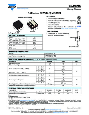
Package InformationVishay D1KD2D1E3E1E2K4KLPIN2beLPowerPAK SC70-6LPIN6PIN4K2PIN5K1K2BACKSIDE VIEW OF SINGLEPIN4K2BACKSIDE VIEW OF DUALADCA1ENotes:1. All dimensions are in millimeters2. Package outline exclusive of mold flash and metal burr3. Package outline inclusive of platingZzDETAIL ZSINGLE PADDIMAMILLIMETERSDUAL 250.4750.5250.0170.0190.021e0.65 BSC0.026 BSC0.65 BSC0.026 BSCK0.275 TYP0.011 TYP0.275 TYP0.011 TYPK10.400 TYP0.016 TYP0.320 TYP0.013 TYPK20.240 TYP0.009 TYP0.252 TYP0.010 TYPK30.225 TYP0.009 TYPK4L0.355 TYP0.1750.2750.014 .0150.050.100.150.0020.0040.006ECN: C-07431 Rev. C, 06-Aug-07DWG: 5934Document Number: 7300106-Aug-07www.vishay.com1
Application Note 826Vishay SiliconixRECOMMENDED PAD LAYOUT FOR PowerPAK SC70-6L Single0.300 (0.012)0.650 (0.026)0.350 (0.014)0.275 (0.011)0.550 (0.022)0.475 (0.019)2.200 (0.087)1.500(0.059)0.870 (0.034)0.235 (0.009)0.355 (0.014)0.350 (0.014)10.650 (0.026)0.300 (0.012)0.950 (0.037)Dimensions in mm/(Inches)Return to IndexAPPLICATION NOTEDocument Number: 70486Revision: 21-Jan-08www.vishay.com11
Legal Disclaimer Noticewww.vishay.comVishayDisclaimerALL PRODUCT, PRODUCT SPECIFICATIONS AND DATA ARE SUBJECT TO CHANGE WITHOUT NOTICE TO IMPROVERELIABILITY, FUNCTION OR DESIGN OR OTHERWISE.Vishay Intertechnology, Inc., its affiliates, agents, and employees, and all persons acting on its or their behalf (collectively,“Vishay”), disclaim any and all liability for any errors, inaccuracies or incompleteness contained in any datasheet or in any otherdisclosure relating to any product.Vishay makes no warranty, representation or guarantee regarding the suitability of the products for any particular purpose orthe continuing production of any product. To the maximum extent permitted by applicable law, Vishay disclaims (i) any and allliability arising out of the application or use of any product, (ii) any and all liability, including without limitation special,consequential or incidental damages, and (iii) any and all implied warranties, including warranties of fitness for particularpurpose, non-infringement and merchantability.Statements regarding the suitability of products for certain types of applications are based on Vishay's knowledge of typicalrequirements that are often placed on Vishay products in generic applications. Such statements are not binding statementsabout the suitability of products for a particular application. It is the customer's responsibility to validate that a particular productwith the properties described in the product specification is suitable for use in a particular application. Parameters provided indatasheets and / or specifications may vary in different applications and performance may vary over time. All operatingparameters, including typical parameters, must be validated for each customer application by the customer's technical experts.Product specifications do not expand or otherwise modify Vishay's terms and conditions of purchase, including but not limitedto the warranty expressed therein.Hyperlinks included in this datasheet may direct users to third-party websites. These links are provided as a convenience andfor informational purposes only. Inclusion of these hyperlinks does not constitute an endorsement or an approval by Vishay ofany of the products, services or opinions of the corporation, organization or individual associated with the third-party website.Vishay disclaims any and all liability and bears no responsibility for the accuracy, legality or content of the third-party websiteor for that of subsequent links.Except as expressly indicated in writing, Vishay products are not designed for use in medical, life-saving, or life-sustainingapplications or for any other application in which the failure of the Vishay product could result in personal injury or death.Customers using or selling Vishay products not expressly indicated for use in such applications do so at their own risk. Pleasecontact authorized Vishay personnel to obtain written terms and conditions regarding products designed for such applications.No license, express or implied, by estoppel or otherwise, to any intellectual property rights is granted by this document or byany conduct of Vishay. Product names and markings noted herein may be trademarks of their respective owners. 2022 VISHAY INTERTECHNOLOGY, INC. ALL RIGHTS RESERVEDRevision: 01-Jan-20221Document Number: 91000
SiA413ADJ www.vishay.com Vishay Siliconix S12-1141-Rev. B, 21-May-12 3 Document Number: 63650 For technical questions, contact: pmostechsupport@vishay.com THIS DOCUMENT IS SUBJECT TO CHANGE WITHOUT NOTICE.