Transcription
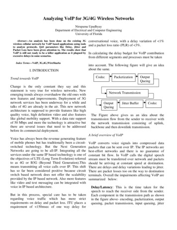
Analyzing VoIP for 3G/4G Wireless NetworksNirupama UpadhyayDepartment of Electrical and Computer EngineeringUniversity of FloridaAbstract—An analysis has been done on the existing 3Gwireless cellular network for VoIP based applications using toolsto analyze protocols. QoS parameters like Delay, Jitter andPacket Loss have been given attention to. The results show thatVoIP is still not ready to be a killer application as it plagued byexcessive delays in some scenarios.Index Terms—VoIP, 3G,4G,WireSharksI. INTRODUCTIONTrend towards VoIPChange is the only constant they say and thisstatement is very true for wireless networks. Newemerging trends always overshadow the old ones withnew features and improvements. Deployment of 3Gnetwork services has been underway for a while andtalks of 4G are already in the air. This new networkarchitecture is supposed to provide features like highquality voice, high definition video and also featureslike global mobility support. With a data rate supportof 50 Mbps and more the technology is attractive butthere are several issues that need to be addressedbefore its commercial deployment.conversational voice, with a delay variation of 1%and a packet loss ratio (PLR) of 3%.In calculating the delay budget for VoIP contributionfrom different segments and processes must be takeninto account. The following figure will give an ideaabout the same.CodecPacketizationOutputQueingNetwork TransmissionOutputQueingJitter BufferCodecThe Figure above gives us an idea about thetransmission flow from the sender to receiver withthe network transmission consisting of uplink,backbone and then downlink transmission.A brief overview of VoIPVoice has always been the revenue generating featureof mobile phones but has traditionally been a circuitswitched technology. But the Next GenerationNetworks are going to be all-IP. Integrating all theservices under the same IP based technology is one ofthe objectives of LTE (Long Term Evolution) referredto as 4G or B3G (Beyond Third Generation).Thismeans transmitting all voice calls over IP. This shifthas so far been considered positive because circuitswitch based network does not offer the scalabilityprovided by the IP based network. Also more featureslike video and text messaging can be integrated withvoice in IP based architecture.But in this process, special care has to be takenregarding voice traffic which has more strictrequirements on delay and packet loss. ITU places arequirement of 150msec of one way delay forVoIP converts voice signals into compressed datapackets that can be sent over IP. The IP networks arebest-effort networks and there is no guarantee ofconstant bit flow. In VoIP calls the digital speechstream must be transferred over network and packetsshould be arriving at constant speed at destination.There are delays and delay variations leading to jitter.There are packet losses too on the way to destinationterminals. Overall the impairments affecting VoIP aresummarized below:Delay/Latency: This is the time taken for thespeech to reach the receiver side from the sender.Each component in the transmission path as shownin the figure above- encoding, packetization, outputqueuing, packet transmission, input queuing, jitter
buffer, decoding - adds delay. The delay increaseswith the number of router hops as well as the codecprocessing contributes to delay. Also greater thesize of the jitter buffer ,more is the delay. Howeverthis parameter can be adjusted in accordance withnetwork environment. The recommendation ofITU-T G.114 to achieve high quality of service is300ms of round-trip delay.As the jitter buffer size is an adjustable parameter,the delay caused by the network causes a deeperimpact. Both one way and round trip delay can bemeasured by various means.Jitter: It is the variation or regularity of packetinter-arrival time. It exists only in packet-basednetworks. This is because the delay inflicted by thenetwork on each packet will be different.Unreasonable jitter makes speech unrecognizable.For high-quality voice, the average inter-arrivaltime at the receiver should be nearly equal to theinter packet gaps at the transmitter with a lowstandard of deviation. Jitter buffers are used tocounteract this impairment of packet networks sincethe compression algorithms on the receiver terminalrequire the packets to have an equal spacingbetween them. The sequence number on the RTPpackets are also used to re-sequence out of orderpacketsPacket spacing change leading to jitterPacket Loss: Packet loss typically occurs either inbursts or periodically due to a consistentlycongested overloaded links, excessive collisions ona LAN and other errors. 5-10 % loss of all voicepackets transmitted can deteriorate the voicequality.With the above impairments in mind, if VoIP is tosucceed as the next revenue generating applicationfor mobile phone market, it has to overcome thesechallenges to make the package attractive to theconsumer.The most important standardization bodies workingon VoIP are ITU-T, IETF, IMTC and ATM Forum.In addition, there are smaller organizations workingon VoIP such as MIT Internet TelephonyConsortium, Technical Advisory Committee etc.The H.323, an ITU standard and SIP, an IETFstandard are the two signaling protocols for VoIP.In the next session I will be giving a briefbackground on the efforts to deploy VoIP over 3Gnetworks and its success so far .Then I will go on topresent the efforts underway for VoIP over 4Gnetworks which is interesting and challenging aswell.II. BACKGROUNDThe road from VoIP over 3G to 4GThe 3rd Generation Partnership Project ons associations in its Release 7gave the specs for HSPA with a focus on decreasinglatency, improvements to QoS and real-timeapplications such as VoIP. The introduction of 3Gnetworks, including WCDMA Release 99, made itpossible to run Voice-over-IP (VoIP) over cellularnetworks with reasonable quality, but with lowerspectral efficiency than circuit switched voice. Withthe following releases namely Release 6 and 7several improvements were made. The architecturefor HSUPA and its influence on VoIP performanceimprovement is given briefly below:The RRM (Radio Resource Management)architecture has undergone changes with every3GPP Release. For the HSDPA/HSUPA cellularnetwork architecture the scheduling moved to NodeB (3G term for BTS) from RNC (Radio NetworkController) in Release 6 .In the earlier release ieRelease 99 the Node B(BTS) was mainlyresponsible for power control.Also in case therewere two RNCs involved for a connection thescheduling was distributed between them .InRelease 6 the SRNC (Serving RNC, the RNCconnected to the core network) decides the QoSparameters as well as suitable handling ofhandovers. QoS management is taken care of by theNode B scheduler as well. As an example VoIP
service can have a higher scheduling priority thanany data service. Also the scheduler buffer can becontrolled by a discard timer which indicates themaximum time packets should be kept in the bufferand then discard when the timer expires. The figureabove gives us an idea of the features of Release 6architecture. There is a new MAC layer MAC-hsadded to the Node B to handle the scheduling. Theterminal also has an additional MAC layer added toit namely MAC-es/s.more efficiently for VoIP traffic over HSPA. Thereis a reduction in data rate from 40kbps to 16kbpsusing the ROHC (Robust Header Compression)approach.The HSDPA/HSUPA protocol architecture can bedivided into the user plane part, handling user data,and the control plane part. The RRC layer in thecontrol plane part handles all the signaling related toconfiguring the channels, mobility management.The Packet Data Convergence Protocol (PDCP) hasas its main functionality header compression asmentioned before. It is done in the user equipment(UE) and in the radio network controller (RNC)therefore, it saves not only air interface capacity butalso Iub transmission capacity.Radio link control (RLC) handles the segmentationand retransmission for both the user and controldata. It has three modes of operation, namely:This is because size of a full IPv6 header togetherwith a Real Time Protocol/User Datagram Protocol(RTP/UDP) header is 60 bytes, while the size of atypical voice packet is 30 bytes. IP headercompression allows using the transmission mediumI. Transparent mode: In this mode no overhead isadded to the RLC layer.II. Unacknowledged mode: In this mode no RLClayer retransmission will take place. This is used
with applications that can tolerate some packet loss,as is the case with VoIP, and cannot allow delayvariation due to RLC level retransmission.Defining terms:HSDSCH is the HSDPA transport channel and EDCH is the HSUPA transport channel.iii. Acknowledged mode operation, when datadelivery is ensured with RLC layer retransmissionswith applications that require all packets to bedelivered.Summarizing simulation results with features inRelease 7 HSDPA/HSUPA [2]:The methods that have been used in HSDPA toimprove the downlink packet data performance aswell as capacity and bit rates are link adaptation,fast scheduling and physical layer retransmissions.Uplink gating: The idea in the gating is to stop thetransmission of the uplink control channel whenthere is no data to be sent on transport channel andno feedback signaling on physical control channel.The gating reduces the uplink interference levels,and therefore, increases the uplink capacityMoving towards 4GSome of the features of this release were:As the third generation mobile systems arebecoming commercialized, research focus hasshifted towards 4G systems. The main transmissiontechnology in 4G proposals such as evolutions ofthe 3GPP long term evolution (LTE) and IEEE802.16isorthogonalfrequency divisionmultiplexing (OFDM), which uses multiple carrierfrequencies dedicated to a single data source.Mobile equalizer: Reduction in intra-cellinterference and improved capacity is anotherfeature of Release 7 due to the introduction of a 2antenna equalizer, which is a Release 7enhancement.Although not as well defines as 3G networkPacket bundling: Turbo code employed in HSDPAperforms more effectively when up to VoIP packetsare bundled together. Circuit switched voice whichused convolution coding transmits 1 voice packetper 20-ms radio frame. The use of packet bundlingfurther improves capacity.Supporting QoS in 4G networks will be challengingdue to varying bit rates, channel characteristics,bandwidth allocation, fault-tolerance levels, andhandoff support among heterogeneous wirelessnetworks. Handoff delay is another important QoSrelated issue in 4G wireless networks. The delay ismore apparent in inter network handovers comparedto intra network because of authenticationprocedures that require message exchange,multiple-database accesses, and negotiationrenegotiation due to a significant differencebetween needed and available QoS.Handoff may lead to the user experiencingsignificant drop in QoS that will affect theperformance of both upper-layer protocols andapplications. Deploying a priority-based algorithmand using location-aware adaptive applications issaid to reduce both handoff delay and QoSvariability.A SUMMARY OF STUDIES CONDUCTED ONVoIP SERVICE OVER HSDPA and LTEPower Scheme: Discontinuous HSDPA receptionfor lower mobile power consumptionAdvanced Node-B HSDPA scheduler: HSDPAVoIP simulations assume proportional fair packetscheduling Code-multiplexing of users (M users).The scheduler selects those M users with highestpriority from the scheduling candidate set fortransmission in the next 2-ms transmission timeinterval (TTI).The criteria for the schedulingcandidates is as follows:1. Users that have a minimum M pkts of VoIPpackets buffered in the Node B. The value for M pktsdepends on the maximum allowed VoIP.2. Users whose head-of-line packet delay is equal toor larger than (M pkts -1) x 20 ms.3. Users with pending retransmissions in theirhybrid automatic repeat request (HARQ) manager.
These criteria help avoid scheduling for users withlow amounts of buffered data in the Node B, whichmight cause a loss of system capacity. A VoIPpacket with ROHC is roughly around 38 bytes or304 bits while the HSDPA transport block sizewith, three high-speed downlink shared channelcodes can be beyond 1500 bits. Therefore, a singletransport block can carry multiple VoIP packets.HSDPA/HSUPA Simulation Result Analysis: Gating improved the capacity to 30-40%.Use of the advanced receiver and theimproved scheduling algorithm improvedthe capacity by 30 % in the experimentalsetup.With the enhancements of Release 5, 6 and 7, thespectral efficiency of VoIP was improved comparedto circuit switched Release 99 solution.Summarizing simulation results with Release 8(4G) features for VoIP performance [16]:Application is what drives the mobile industry witheach application having its own specialrequirement. Some are tolerant to delay and some topacket loss and some which are tolerant to neither,VoIP being one of them. One of the maincontributors to delay in an IP based network isretransmissions. In this discussion I will summarizesome aspects of 4G networks that have beensimulated and studied. The delay requirements forVoIP, as stated by ITU-T is, 150msec of one waydelay for conversational voice. However thecontribution to delay in a 4G or 3G cellular networktraffic is by wireless link and fixed link as well. Thefixed network delay cannot be controlled. Thebuffer at the receiver to combat jitter contributes tothe increase in total delay before playback. Thetraditional method of using FEC (whereretransmissions are not required) for voice traffic isnot optimal to capacity and is more complicated asit required different ARQ/FEC for varying trafficclasses.The system design in 3G cause high transmissiondelays, however 4G has a target of 8 ms HARQRTT, as well as 2 ms HARQ RTT. Theperformance of VoIP applications can be measuredin a number of ways, for example with regard todelay, jitter and packet loss. There are alsoperceptual models Mean Opinion Score (MOS),Perceptual Evaluation of Speech Quality (PESQ),and the E-Model which are based on the userexperience. The simulation that will be summarizedbelow has taken the following considerations:1. InthedownlinkOFDMAcodedtransmissions divided in time and frequencywas used: 1500x25 frames per second, overa 5 MHz channel in the 1900 MHz band.Each time-frequency slot, consists of 108symbols. The symbols are modulated with 1to 8 bits/symbol corresponding to uncodedBPSK to 256- QAM modulation. Themodulation is adaptive so the data ratevaries between limits.2. Frame retransmissions are used till a limit isreached.3. Queuing is not considered as transmissionsoccur below link capacity.In this setup the traffic was transmitted from a fixedsender to a mobile receiver. This gave a packetstream of 50 packets/s with 172 byte payload. Thetraffic was generated and captured with thesimulation tool used in the experimental setup.Reliability and delay has a tradeoff whereretransmissions for reliability lead to delay andlimiting retransmissions reduce delay with anegative impact on reliability. It is observed thatretransmission delay impacts the delay in moreprofound way. So short delay loops as promised by4G will lead to reduced delay. A link retransmissiondelay of 2 ms resulted in a packet delay of 20 msover the wireless link, and 8 ms link retransmissiondelay resulted in a packet delay of 50 ms. Thehighest link retransmission delay tested, 16 ms,resulted in an 80 ms upper delay bound which is agood margin for 150 ms end-to-end delay for voiceover IP.IV. EXPERIMENTMost of the experiments and simulations are donewith some limitations and considering optimalconditions. I have procured a 3.5G (marketed as 3Gby AT &T) data card. The following map gives a
coverage area and the cell tower locations of AT &T around Gainesville.sip.gatorphone.com with phone numbers acquiredfrom IPKall as well as another VoIP toolVoipRaider. One of the System had 3.5G card withtypically 700 Kbps - 1.7 Mbps download / 500Kbps - 1.2 Mbps uplink and the other with standard40Mbps internet connection.Between 3.5G and standard High Speed Internet(HSI) (Cox Connection):Observations: It is observed that the drop byjitter buffer is more in the direction from the 3Gto the HIS Connection user than the reversedirection. However the RTP packet loss is notvery significant in both directions.A print shot of the graph analysis done byWireshark is shown below :The specific tower locations were procured fromAT & T site. I used VoIP raider and Xlite using thesip server (sip.gatorphone.com).The summary of thefield tests conducted under different test conditionsand the results are given below. Also the scenariosthat could not be tested and the reasons thereof arealso explained below.Limitation: For this scenario due to the availabilityof one data card test could be performed with onlyone of the calling parties having 3G and the otherbeing either 2G (Cellular Phone) or High SpeedCox Internet Connection delivering 50 Mbps of datarate.Tool Used for the Analysis: WireShark Version1.0.5, a free Network Protocol Analyzer distributedand released under the GNU General PublicLicense.Fig 1Scenario # 1 : Both the callers are in a standingstatic position (With no motion)Two laptops, Widows Vista Basic operating systemwith Xlite installed and configured toAs we see in the Fig 1 above the followinginformation is provided by the graph analysis:
Two columns representing the IP addresses of thetwo callers.Fig 2 An arrow showing the direction of eachpacket in the callsThe label on top of the arrow showsmessage type. It shows the codecs availablenamely iLBC, g729, GSM, g711A, g711Uand speex.Shows the UDP/TCP source and destinationport per packet.Protocol dependent information is shown inthe last column.The first message is an INVITE message to startthe call.After an exchange of few moremessages the RTP stream is established betweenthe two points through the Session DescriptionProtocol (SDP) which carries the informationabout codecs, IP addresses and port numbersthat is necessary for VoIP to work. RTP streamsbeing unidirectional, a full duplex conversationis setup by setting up separate RTP streams ineach direction using two separate SDPmessages.Fig 2 is a screenshot of the RTP Player. It shows theRTP streams available for the calls made.The RTP packets that are dropped by jitter buffer aswell as out of sequence packets are reported in thewindow. Between 3.5G and GSM 2G Phone:Observations: It is observed here that RTP packetloss in both directions is more significant than thedrop by jitter buffer.The Graph display for this experiment is verysimilar to the one described above with the samesequence of events as described above for the testscenario. Fig 3 is a screenshot of the RTP screenanalysis showing the out of sequence packets duringthe course of the 3G to 2G voice call.An average data rate of 90Kbps was reported inWireShark for separate LAN scenario and data rateof 7 Kbps was reported between 3G and 2G call.The table below gives a summary of results forScenario #1Scenario Average Maximum AveragePacketJitter(ms) Delay(ms)LossVoIP0.0012623(3G–using 3G0.06%HIS)to HIS174VoIP(Opp.)separateLANVoIPusing 3Gto HISVoIPsameLANVoIPusing3G %2356(3G–2G)102(Opp.)
Fig 3Scenario # 2: Caller with 3G card is in motion inthe area spanning two cell towers while thesecond caller is static.Between 3.5G and standard High Speed Internet(Cox Connection):Observations: Packet loss, Delay as well as Jitterdrastically increases. Also the codec that is usedfor voice changes from g711U in the previousscenario to iLBC (internet Low Bit Rate Codec ).The bit rate supported by it is 15.2 kbps. It has acontrolled response to packet loss and jitter. It wasalso observed that the packet delay from 3G toHIS was less than that from HIS to 3G. UsingXlite configured to sip.gatorphone.com causedmore echo and packet loss compared to VoipRaider.Fig. 4In Fig 4 we see that the receiver asking for ProxyAuthentication and iLBC codec being used forvoice transfer.Also it is observed that in extreme cases the delayhas gone up to 12 seconds with 3.25 % packet lossas shown in Fig 5. In this case the call had to bereestablished for proper communication betweenthe two VoIP clients. There were two instances ofcall drops in the course of calls due to heavypacket-loss and jitter. The average data ratereported was 37.2 Kbps.Fig.5
Also the drop by jitter varied from .7% to 15 % isboth directions which contributed by theexcessive packet loss due to the jitter bufferScenario3G to HISAverageMaximumPacketJitter (ms)Loss0.00-.21%Between 3.5G and GSM 2G Phone:Observation: The results of this scenario arepredictable and regulated without any erraticbehavior. Even in this case the packet loss anddelay in the direction from 3G system to 2Gphone is more significant. Also the data ratereported in WireShark was 29 Kbps3G to 2G0.000.10%29AverageDelay(ms)99(3GHIS)564 (Opp.)83(3GHIS)342(Opp.)It is to be mentioned here that during the testingof scenario # 2, the laptop with a platformconsisting of Intel Core II Duo and Vista HomeBasic drained out of battery an hour earlier. Inother words the backup lasted for 2 and ½ hoursinstead of 3 and ½.V CONCLUSION AND FURTHER STUDYFrom the results we see that delay in Part 1 of thefirst scenario namely between two separate LANsusing 3G and HIS on the two sides and delaywhile the 3G card user is in motion far exceedsthe ITU-T recommendations.Fig 6From the screenshot of graph analysis windowabove we see that of the various messagesexchanged between the terminals the codec used isGSM which is the codec used by GSM phones. Wealso notice a DTMF ( Dual Tone Multi Frequency)signal.Dual-tone multi-frequency (DTMF) signaling isused for telecommunication signaling over analogtelephone lines in the voice-frequency bandbetweentelephone handsetsandothercommunications devices and the switching center.In the table below are the results of Scenario #2:It is also to be noted that in situations where boththe HSI and 3G were available, both theconnections were active. So the operating systemshould be configured to relinquish the low speedconnection when a higher speed connection isavailable.Further study has to be done on 3G to 3G in boththe scenarios as well as using 4G card as andwhen they are available.VI. REFERENCES[1] HSDPA/HSUPA for UMTS High Speed RadioAccess for Mobile Communications , Harri Holmaand Antti Toskala.[2] VOIP OVER HSPA WITH 3GPP RELEASE 7,Harri Holma, Markku Kuusela, Esa Malkamäki,Karri Ranta-aho, Chen Tao[3] Enhancing Performance of VoIP over HSDPA,Petteri Lundén, Markku Kuusela[4] Performance of VoIP on HSDPA, Bang Wang,Klaus I. Pedersen Troels E. Kolding, and Preben E.Mogensen
[5] VoIP Service on HSDPA in Mixed TrafficScenarios, Yong-Seok Kim[6] Voice over IP (VoIP) over Cellular: HRPD-Aand HSDPA/HSUPA Weimin Xiao, AmitavaGhosh, Dennis Schaeffer, Lawrence Downing[7] Agilent 3GPP Long Term Evolution: SystemOverview, Product Development, and TestChallenges[8] Towards the 4G José Jiménez[9] Emerging Trends in the Mobile VoIP BusinessHANNU VERKASALO[10] 4G: An Idea Whose Time has Come?4GForumPaul Henry, AT &T[11] On the VoIP Capacity of an OFDMA UplinkPatrick Hosein Huawei Technologies Co., ions Systems: A Roadmap to 4GLiljana M. Gavrilovska, Vladimir M. Atanasovski[13] Performance Analysis of VoIP Services in theIEEE 802.16e OFDMA System With InbandSignaling Jae-Woo So[14] Uplink Capacity of VoIP on LTE System,Haiming Wang Dajie Jiang Esa Tuomaala[15] Adaptive Contention Resolution for VoIPServices in the IEEE 802.16 Networks A. Sayenko,O. Alanen and T. Hamalainen[16] Impact of 4G Wireless Link Configurations onVoIP Network Performance Stefan Alfredsson,Anna Brunstrom, Mikael Sternad[17] http://www.protocols.com/papers/voip2.htm
ITU-T G.114 to achieve high quality of service is 300ms of round-trip delay. As the jitter buffer size is an adjustable parameter, the delay caused by the network causes a deeper impact. . possible to run Voice-over-IP (VoIP) over cellular networks with reasonable quality, but with lower spectral efficiency than circuit switched voice. With