Transcription
TECHNICAL SERVICE BULLETINTITLE:Cabling Guidelines for ImprovingVoice over Internet Protocol (VoIP) QualityNUMBER:56006180ISSUE:GARELEASED:November, 2003PRODUCTS AFFECTED:(3300 ICP, 3100 ICP and so forth)SEVERITY:Mitel Networks VoIP SystemsNON-CRITICAL (INFORMATION ONLY)AUDIENCE:This Technical Service Bulletin isintended for Customer Service and Installation personnel involved in theinstallation and maintenance of the Mitel Networks VoIP systems.56006180Page 1of 9
NOTICEThe information contained in this document is believed to be accurate in all respects, but is not warranted by Mitel NetworksCorporation (Mitel). The information is subject to change without notice and should not be construed in any way as a commitment byMitel or any of its affiliates or subsidiaries. Mitel and its affiliates and subsidiaries assume no responsibility for any errors or omissionsin this document. Revisions of this document or new editions of it may be issued to incorporate changes.56006180Page 2of 9
PurposeThis Technical Service Bulletin (TSB) provides Ethernet cabling guidelines for Mitel Networks systems.The ProblemMitel Networks systems, such as the 3100 ICP and 3300 ICP, transmit voice signals over a data network usingVoice over Internet Protocol (VoIP). Electrical interference in the environment can reduce the quality of thevoice and data signals that are transmitted over Ethernet cable. Desktop computers, printers, servers, lightingand other office devices place a high demand on the electrical infrastructure and increase the risk of electricalinterference. You can minimize electrical interference and improve network efficiency by following the cablingguidelines detailed in this Technical Service Bulletin.Note: Special testing equipment is available from Mitel Networks Professional Services that can verify Ethernetcable performance and detect cable faults. This service is available for a fee.Maximum Cable LengthsLimit the CAT 5 or CAT5e Ethernet cable runs to the lengths listed in Table 1.TABLE 1: MAXIMUM CABLE LENGTHS56006180CablingMaximum LengthUnder desk3 m (10 ft)Floor to ceiling3.5 m (11.5 ft)Horizontal span in ceiling90 m (300 ft)Equipment closet3.5 m (11.5 ft)Total maximum length100 m (333 ft)Page 3of 9
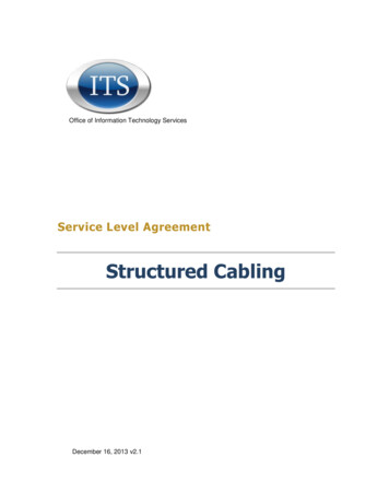
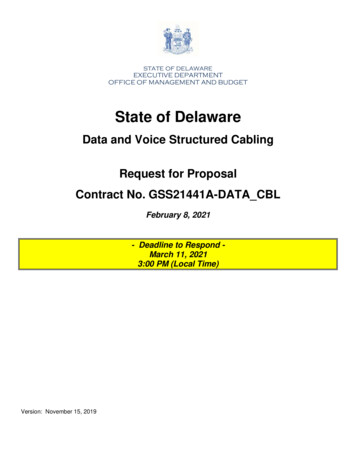
Cabling Guidelines for the DesktopRefer to Figure 1 and the corresponding cabling guidelines in Table 2 to minimize electrical interference at thedesktop.FIGURE 1: DESKTOP ENVIRONMENT56006180Page 4of 9
TABLE 2: DESKTOP ENVIRONMENT CABLING GUIDELINESConnectionGuidelinesAEthernet connection to network Use CAT 5 or CAT 5e Ethernet cables and certified networkconnection blocks (TIA/EIA 568A). Adhere to the cable lengths listed inTable 1BNetwork to power adapter Ethernetpatch cable (for local powerconfiguration only) Use CAT 5 or CAT 5e cables (certified to TIA/EIA 568A) Maximum length of 1.5 m (5 ft) Route cable away from sources of interference, such as powercablesCIP Phone power adapter (for localpower configuration only) Plug IP Phone power adapter and the computer into the samesurge suppressing power bar.DSurge suppressing power bar Recommended model is American Power Conversion“SurgeArrest” EPower outlet for desktopequipmentRoute power cables away from Ethernet cables Use outlet to supply power to computer and IP Phone poweradapter only Do not plug other devices such as florescent lights, coffee makers,kettles into this outletFPhone to power brick Ethernetconnection Use CAT 5 or CAT 5e cables (certified to TIA/EIA 568A) Maximum length of 1.5 m (5 ft) Route cable away from sources of interference, such as powercablesGMonitor power cord Plug into computer power barHComputer power cord Route cable away from Ethernet cablesIComputerJPhone to computer Ethernetconnection Use CAT 5 or CAT 5e cables (certified to TIA/EIA 568A) Maximum length of 1.5 m (5 ft) Route cable away from sources of interference, such as powercablesKKeyboard to computer connection Route cable as required for convenienceLMonitor to computer connection Route cable away from Ethernet cablesMPower connection to auxiliaryequipment Use a separate power outlet for potential noise generating devicessuch as a lamp, coffee maker, or radioNFlorescent light power cord 56006180Route cable away from Ethernet cablesPage 5of 9
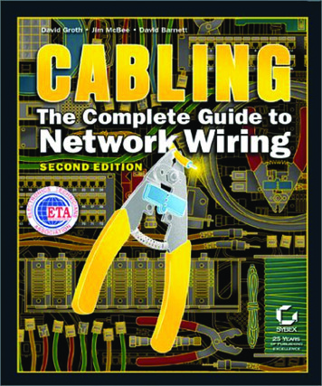
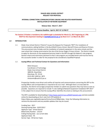
OFlorescent desk light Ballast circuitry inside florescent lamps will create noise spikes onpower cables when the lamps are turned off. Ensure that florescent lampsare plugged into dedicated surge suppressing power bars. Voltage limitingdevices inside the power bars reduce noise spikes and reduce the risk ofdata errors. Some desks have power outlets that are designated for thecomputer and utility devices. These outlets have built-in surge protection.In this case, a power bar is not required.Cabling Guidelines in the Equipment RoomRefer to Figure 2 and the corresponding cabling guidelines in Table 3 to minimize electrical interference in theequipment room.FIGURE 2: EQUIPMENT ROOM ENVIRONMENT56006180Page 6of 9
.56006180Page 7of 9
TABLE 3: EQUIPMENT ROOM CABLING GUIDELINESConnectionGuidelinesA Use CAT 5, CAT 5e, or CAT 6 Ethernet connector blocks andcables3300 ICP or 3100 ICP controller CAT 5e or CAT6 certified cable provides better immunity tocrosstalk Connect ground stud on back of controller to ground bar bus (G)with a dedicated ground wireBPatch panel Patch panels must be certified for CAT 5 cable Do not use punch down blocks that are designed for voice-gradetelephony signals to interconnect 100 Mb/s Ethernet signals. Recommended connector blocks can be obtained fromwww.anixter.com (part number 201011)CLayer 2 switch If a ground stud is provided, connect it to ground bar bus (G) with adedicated ground wire. Use the wire gauge specified by the manufacturerDPowered hub Powered hubs supply IP Phones with power through the Ethernetcable either through the spare wires or the signal pairs. IP Phones thathave power adapters do not use powered hubs. If a ground stud is provided, connect it to ground bar bus (G) with adedicated ground wire. Use the wire gauge specified by the manufacturerEProtected power system Dedicate the use of the power outlets to the equipment in theequipment room only. Ensure that the power outlets in the equipment room are wired for15 Amp service directly to the electrical service panel with ideally onecircuit breaker per outlet. If the site is configured with resilient IP phones, ensure that the3300 controllers are powered by dedicated Switching power supplies common in computers andtelecommunications equipment generate noise voltages, known asharmonics. Use oversize neutral conductors to minimize harmonics.FCable56006180 Ensure that conduits include a dedicated copper ground Ensure that the maximum cable runs do not exceed 100 m.Page 8of 9
GGround bar bus Use a ground bus bar that is ¼ inch thick and 2 inches wide andlong enough to accommodate the grounding for all the rack-mountedequipment Recommended bus bar is ANIXTER part number 179639 Mount the bus bar on the wall with insulated standoffs barUse compression style fittings to fasten the ground wire lugs to the Connect the bus bar to the main building ground with a 6 AWGcopper stranded green-colored cable. For grounding specifications see ITU-T K.27 “Buildingconfigurations and earthings inside a telecommunications building” andANSI/TIA/EIA-607HProtected rack-mount power strip If you cannot provide dedicated 15 Amp power outlets for each unitin the rack, mount a surge arresting power strip on the front or rear of therack. Recommended model is the Surge Arrest – Rack Mount modelfrom American Power Conversion. The ground from the rack forms part ofthe shield for the power strip. Plastic floor type models are not recommended because they aremore likely to be turned off by accident.Caution: Power bars have a circuit breaker. If the circuit breaker is trippeddue to a power surge, the power to all the outlets on the power bar is shutoff. If the site supports resilient IP Phones, ensure that the controllers areplugged into different power bars.IStandard metal rack Bolt each rack securely to the floor and connect a dedicatedground wire between the frame and the ground bus bar. If rack-mounted equipment obtains safety ground from the metalrack, ensure that a good electrical connection is made between the rackand the cabinet metalwork. Use “star” washers to obtain a solid electricalconnection to painted cabinets Route any power cables contained within the rack away from anyUTP patch cablingNote: Fiber optic cabling can be routed anywhere within the rack becauseit is not susceptible to electrical emissions.JAC Mains metal conduitMetal conduit that contains power wiring must three wires for eachdedicated circuit: Ground (bare), Neutral (White), Hot or Line (Black). Donot use the conduit as the ground.KTelecoms main ground Main ground connector must be 6 AWG stranded copper, greencolored cable connected to the main building ground.Caution: A proper ground is required for proper equipment operation andsafety. A power quality engineer can provide advice on new and existinginstallations. Refer to G for additional information.LRack grounds56006180 Use separate wires to ground each rack to the ground bus barPage 9of 9
MEquipment grounds Use separate wires to ground each piece of equipment to theground bus bar. If a ground stud is provided on the back of the unit,connect it to the ground bus bar with a dedicated ground wire (use thegauge specified by the manufacturer).NPatch cable Interconnect Ethernet equipment supporting 100 Mb/stransmission with CAT 5 UTP patch cable. Label the cables and route themneatly through the channels provided in the metal rack.Caution: Do not use voice grade twisted pair interconnect patch cablewired to standard voice grade punch-down blocks on an IDE.OMetal rack interconnect The metal brackets used to connect the racks provide mechanicalconnection only. Use a dedicated ground wire to ground each rackseparately to the ground bus bar.PCable tray ground Connect the metal racks that house the Ethernet cable to theground bus bar to provide an effective shield against from potential noisesources such as power lines and florescent lights.QCable tray The tray should contain Ethernet cables only. Do not mix powercables with Ethernet cables56006180Page 10of 9
Voice over Internet Protocol (VoIP) Quality NUMBER: 56006180 ISSUE: GA RELEASED: November, 2003 PRODUCTS AFFECTED: Mitel Networks VoIP Systems (3300 ICP, 3100 ICP and so forth) SEVERITY: NON-CRITICAL (INFORMATION ONLY) AUDIENCE: This Technical Service Bulletin is intended for Customer Service and Installation personnel involved in the