Transcription
COMPACT FIRE PUMP SYSTEMLIFTING MANUALLIFTING & MOVING INSTRUCTIONS@2016, Pentair Flow & Filtration Solutions
TABLE OF CONTENTS1. Safety Symbols & Terminology. . .22. Compact Fire Pump System – (Lifting Manual) . . .32.1 Basic Know-How Of Compact Fire Pump System . 32.2 Lifting . .42.2.1 Total weight of the system .(For minimum capacity requirements of forklift)4Maximum outside dimensions . 52.2.22.3 Procedure . .62.4 General Safety Instructions . .7CFPS-LM-P1/R0
1. SAFETY SYMBOLS & TERMINOLOGYCAUTION: A hazardous situation which, if not avoided, could result in minor or moderateinjury.WARNING: A hazardous situation which, if not avoided, could result in serious injury.DANGER: A hazardous situation which, if not avoided, will result in serious injury.CFPS-LM-P2/R0
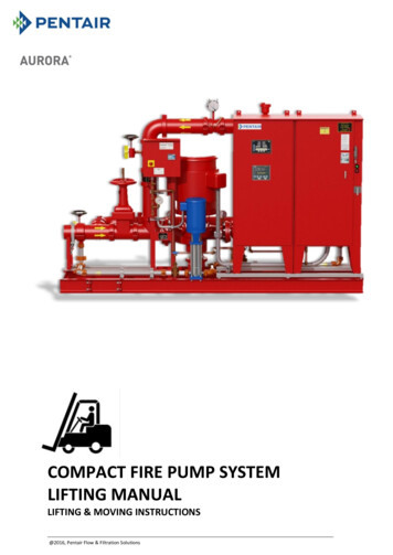
2. COMPACT FIRE PUMP SYSTEM – (LIFTING MANUAL)CAUTION: This manual is meant only for lifting of the system. This manual should be keptin a safe place and ALWAYS be available to the QUALIFIED operating and maintenancepersonnel.For more information regarding the system, please refer “Operation & Maintenancemanual” of the same. A basic understanding of the system and its components can be builtby reading the following heading.2.1 BASIC KNOW-HOW OF COMPACT FIRE PUMP SYSTEMTest Loop LineFire PumpJockey ControllerBypass LoopFire PumpControllerJockey PumpSkidAurora offers a complete fire pump system that has a small footprint, ideal for buildingswith limited space. This pre-engineered system is factory assembled and ready to start, withonly base grouting and pipe and power connections to be completed at site. Ideal for Smaller Areas – Fits through a 36" Doorway* Multiple Starting Methods for the Fire Pump with Optional Automatic Transfer Switch Optional City Bypass & Test loop*Bypass loop (if there) need to be removed to pass through 36” door.CFPS-LM-P3/R0
2.2 LIFTINGPrior to lifting and moving the system, find out the following: Total weight of the system. Maximum outside dimensions.2.2.1 Total weight of the system :It should be known for minimum capacity requirements of forklift. The table 1.1 shows thedimensions and weight (excluding the weight of pump and fire pump controller) of aCompact Fire Pump System with given flow capacity. The minimum capacity requirementsof forklift can be determined by adding the maximum weight of controller (B) & fire pump(C) to the maximum weight of the rest of the system (A). The maximum weight ofcontroller & fire pump can be figured out from the below tables 1.2 & 1.3 respectively.Maximum weight of the system, T A B CNow,Minimum capacity of the forklift should be, Cm [T Forklift Load Centre adjustment*] lbs*Refer Forklift catalogue for details.CAUTION: Maximum weight of the system is to be used for calculation of minimumcapacity requirements of forklift. The actual weight of the system may however vary as perthe system flow. Refer catalogue & drawing(s) for accurate dimension & weight data.Flow RangeOptionLengthWidthHeightMax. Weight 050870900740Table 1.1Here, AO- All Options, B- With Bypass Loop, T-With Test Loop & NO- With Test Header OnlyCFPS-LM-P4/R0
Controller MakeTransfer SwitchMax. WeightFire PumpMax. ster ControllerYES9003-383-9595Master 383-97004-383-9B7004-383-9C574Table 1.2Table 1.32.2.2 Maximum outside dimensionsThe maximum outside dimensions of the system can be found from the table 1.1. Thefollowing pictures show the length, width & height of a Compact Fire pump System.Height is the maximium vertical dimension of the system measured from the bottomost point of skid to the topmost point of fire pumpcontroller / flowmeter whatever the case may be.CAUTION: Actual maximum dimensions of the system may vary as per the system flow.The dimensions shown in the table above are the maximum values in the mentioned flow.range.CFPS-LM-P5/R0
2.3 PROCEDUREI.II.III.IV.ForkliftthissideV.VI.VII.Only Forklift or lull forklift should be used for lifting & moving the system. Avoidlifting system by slings, eye-bolts etc.Ensure that forks are level and high enough to go under the skid but it should not hitthe load.System can be lifted from either side by forklift. However preference should be givento lift it from controller end.The length of the forks should be such that it should cross the red shaded channelbelow the pump if the system is lifted from controller end. However, it should crossthe green shaded channel if lifted from the other end as shown below. Notcomplying with this may result in toppling of the system causing damage topersonnel or property.ForkliftthissideLift the load straight up until it is clear & then tilt back and drive with the loadagainst the backrest.Look for overhead hazards both when lifting a load and while travelling.Watch that the load or forks do not catch on adjacent loads or obstructions.WARNING: Systems with Bypass line may be unstable during lifting. Use ofslings/additional weight on the controller side is recommended in such case for balancingpurpose otherwise toppling may occur.CFPS-LM-P6/R0
2.4 GENERAL SAFETY INSTRUCTIONSStrictly obey to the following instructions to prevent personal injuries and/orequipment ing regulations for the prevention of accidents must be followed.Wearing of gloves, hard-toed boots and hard hats is obligatory for all transportworks.Wooden cases, crates, pallets or boxes may be unloaded with forklift trucks or usinghoisting slings, depending on their size, weight and construction.A first aid kit as per the Health and Safety Authority’s travel kit recommendationswith all the contents properly checked for expiry.A safely stowed fire extinguisher according to the industrial safety norms.Operator of the hoist equipment must follow proper rigging procedure.For stable positioning of the unit without any risk of accident, always make sure thatthe pump system remains in horizontal position during transport and cannot slip outof the transport suspension arrangement.For transport purposes the unit may be secured on suitable pallets or sleds.All loose and movable parts must be secured.Examine lifting devices to determine their load capacity. Employers must have theseexaminations conducted in accordance with the regulations, for example, beforeusing a lifting device for the first time.Do not attempt to transport the unit until you have read the safety precautions inthis publication.Lifting of the system should be only carried out when the unit has been brought tostandstill position.WARNING: Always disconnect the power to the system and make sure that it should notbe switched on accidentally before attempting to move the system.CAUTION: Motor or Controller lifting holes are not meant for entire system lifting.CFPS-LM-P7/R0
COMPACT FIRE PUMP SYSTEM LIFTING MANUAL LIFTING & MOVING INSTRUCTIONS. CFPS-LM-P1/R0 . controller & fire pump can be figured out from the below tables 1.2 & 1.3 respectively. . Firetrol NO 415 3-383-7C 386 Master Controller YES 900 3-383-9 595 Master Controller NO 650 3-383-9A 566 Metron YES 570