Transcription
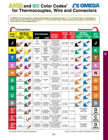
APPENDIX BThe information contained in this appendix is intended to supplement informationfor existing practices found within CGA Best Practices.8/BEST PRACTICES CHAPTER 4—LOCATING AND MARKINGPractice Statement 4–3: Color Code: A uniform color code and set of marking symbols isadopted nationwide.Uniform Color Code9/The following APWA uniform color code (ANSI Z535.1) shall be adopted as theuniform color code for marking excavation sites and underground facilities inconflict with an excavation. This recommendation is not intended to preempt anyexisting state requirement that specifies other colors.References: APWA Uniform Color Code Existing operating practices from various states’ one call centers Existing one call laws from various states ANSI Standard Z535.1 Safety Color Code.–95–Appendix B: Uniform Color Code and Marking GuidelinesUniform Color Code andMarking Guidelines
CGA Best Practices 18.0BEST PRACTICES CHAPTER 5—EXCAVATIONPractice Statement 5–19: Excavation Tolerance Zone: The excavator observes a tolerancezone that is comprised of the width of the facility plus 18 in. on either side of theoutside edge of the underground facility on a horizontal plane. This practice is notintended to preempt any existing state/provincial requirements that currently specifya tolerance zone of more than 18 in.Tolerance Zone40/Appendix B: Uniform Color Code and Marking GuidelinesThe following examples are of tolerance zones for a 1 in. and 12 in. line:–96–
Uniform Color Code and Marking GuidelinesGuidelines for Excavation Delineation9/The following marking illustrations are examples of how excavators may choose tomark their area of proposed excavation. The use of white marking products (e.g.,paint, flags, stakes, whiskers, or a combination of these) may be used to identifythe excavation site.Single Point Excavations MarkingsDelineate in white62/ the proposed area of excavation using a continuous line, dotsmarking the radius or arcs, dashes marking the four corners of the project, ordashes outlining the excavation project. Limit the size of each dash toapproximately 6 in. to 12 in. long and 1 in. wide with interval spacing approximately4 ft to 50 ft apart. Reduce the separation of excavation marks to a length that canreasonably be seen by the operator’s locators when the terrain at an excavationsite warrants. Dots of approximately 1 in. diameter typically are used to define arcsor radii and may be placed at closer intervals in lieu of dashes.Single Stake Marking Center Point of Excavation SiteWhen an excavation site is contained within a 50 ft maximum radius or less, it canbe delineated with a single stake that is positioned at the proposed center of theexcavation. If the excavator chooses this type of delineation, they must convey thatthey have delineated the excavation site with a single stake at the center of theexcavation and include the radius of the site in the notification to the one call center.This single stake is white in color and displays the excavator’s company identifier(name, abbreviations, or initials) and the radius of the excavation site in blackletters on the stake or with a notice attached to the stake.–97–Appendix B: Uniform Color Code and Marking GuidelinesBEST PRACTICES CHAPTER 5—EXCAVATIONPractice Statement 5–2: White Lining67/: When the excavation site cannot be clearly andadequately identified on the locate ticket, the excavator designates the route and/orarea to be excavated using white premarking, either onsite or electronically (whenavailable through the one call center), prior to or during the request for the locateticket.
CGA Best Practices 18.0Trenching, Boring, or Other Continuous-Type ExcavationsAppendix B: Uniform Color Code and Marking GuidelinesContinuous Excavation MarkingMark in white62/ the proposed centerline of planned excavation using 6 in. to12 in. 1 in. arrows approximately 4 ft to 50 ft apart to show direction ofexcavation. Reduce the separation of excavation marks to a length that canreasonably be seen by the operator’s locators when the terrain at an excavationsite warrants. Mark lateral excavations with occasional arrows showing excavationdirection from centerline with marks at curb or property line if crossed. Dots may beused for curves and closer interval marking.Stake, Flag, or Whisker Excavation MarkersDelineate the proposed area of excavation using stakes, flags, or whiskers insteadof spray paint to mark radius or arcs; the four corners of the project; or whenoutlining the excavation project. Limit the interval spacing to approximately 4 ft to50 ft. Reduce the separation of excavation marks to a length that can reasonablybe seen by the operator’s locators when the terrain at an excavation site warrants.Stakes, flags, or whiskers provided to illustrate arcs or radii may be placed at closerintervals to define the arc or radius. Stakes, flags, or whiskers are white in color anddisplay the excavator’s company identifier (name, abbreviations, or initials).–98–
Uniform Color Code and Marking GuidelinesBEST PRACTICES CHAPTER 4—LOCATING AND MARKINGPractice Statement 4–3: Color Code: A uniform color code and set of marking symbols isadopted nationwide.Operator markings of facilities include the following: The appropriate color for their facility type Their company identifier (name, initials, or abbreviation) when othercompanies are using the same color The total number of facilities and the width of each facility A description of the facility (HP, FO, STL, etc).Use paint, flags, stakes, whiskers, or a combination to identify the operator’sfacility(s) at or near an excavation site.1.Marks in the appropriate color are approximately 12 in. to 18 in.long and 1 in.wide, spaced approximately 4 ft to 50 ft apart. When marking facilities, theoperator considers the type of facility being located, the terrain of the land, thetype of excavation being done, and the method required to adequately markthe facilities for the excavator.2.The following marking examples illustrate how an operator may choose tomark their subsurface installations:a.Single Facility Marking: Used to mark a single facility. This can be donein one of two ways—1) placing the marks over the approximate center ofthe facility:or 2) placing the marks over the approximate outside edges of the facilitywith a line connecting the two horizontal lines (in the form of an H) toindicate there is only one facility:These examples indicate an operator’s 12 in. facility. When a facility canbe located or toned separately from other facilities of the same type, it ismarked as a single facility.41/–99–Appendix B: Uniform Color Code and Marking GuidelinesGuidelines for Operator Facility Field Delineation9/
CGA Best Practices 18.0b.Multiple Facility Marking: Used to mark multiple facilities of the sametype (e.g., electric), where the separation does not allow for a separatetone for each facility, but the number and width of the facilities is known.Marks are placed over the approximate center of the facilities and indicatethe number and width of the facilities.Appendix B: Uniform Color Code and Marking GuidelinesExample: four plastic facilities that are 4 in. in diameter (4/4" PLA)c.Conduit Marking: Used for any locatable facility being carried insideconduits or ducts. The marks indicating the outer extremities denote theactual located edges of the facilities being represented.Example: four plastic conduits that are 4 in. in diameter (4/4" PLA), andthe marks are 16 in. apart, indicating the actual left and right edges of thefacilitiesd.Corridor Marking: Used to mark multiple facilities of the same type (e.g.,electric), bundled or intertwined in the same trench, where the totalnumber of facilities is not readily known (operator has no record on file forthe number of facilities). Marks are placed over the approximate center ofthe facilities and indicate the width of the corridor. The width of thecorridor is the distance between the actual located outside edges of thecombined facilities.Example: a 12 in. corridor (12" CDR)–100–
Uniform Color Code and Marking Guidelines3.Changes in direction and lateral connections are clearly indicated at the pointwhere the change in direction or connection occurs, with an arrow indicatingthe path of the facility. A radius is indicated with marks describing the arc.When providing offset markings (paint or stakes), show the direction of thefacility and distance to the facility from the markings.Appendix B: Uniform Color Code and Marking GuidelinesExample: radiusExample: lateral connectionExample: painted offset (off)Example: staked offset (off)–101–
CGA Best Practices 18.04.An operator’s identifier (name, abbreviation, or initials) is placed at thebeginning and at the end of the proposed work. In addition, subsequentoperators using the same color mark their company identifier at all pointswhere their facility crosses another operator’s facility using the same color.Reduce the separation of excavation marks to a length that can reasonably beseen by the operator’s locators when the terrain at an excavation sitewarrants.Examples:CITYCOAppendix B: Uniform Color Code and Marking Guidelines5.ELECOTELCOInformation regarding the size and composition of the facility is marked at anappropriate frequency.Examples: the number of ducts in a multi-duct structure, width of a pipeline,and whether it is steel, plastic, cable, etc.TELCO9/4" CAB6.GASCO4" PLAWATERCO12" STLFacilities installed in a casing are identified as such.Examples: 6 in. plastic in 12 in. steel and fiber optic in 4 in. steelGASCO6" PLA/12" STL7.TELCOFO (4" STL)Structures such as vaults, inlets, and lift stations that are physically larger thanobvious surface indications are marked so as to define the parameters of thestructure.Example:8.Termination points or dead ends are indicated as such.Example:9.When there is “No Conflict” with the excavation, complete one or more of thefollowing: Operators of a single type of facility (e.g., TELCO) mark the area “NO”followed by the appropriate company identifier in the matching APWAcolor code for that facility.Example: NO TELCO Operators of multiple facilities mark the area “NO” followed by theappropriate company identifier in the matching APWA color code for thatfacility with a slash and the abbreviation for the type of facility for whichthere is “No Conflict.”Example: NO GASCO/G/D illustrates that GASCO has no gas distributionfacilities at this excavation site. The following abbreviations are used whenappropriate: /G/D (gas distribution); /G/T (gas transmission); /E/D (electricdistribution); /E/T (electric transmission).–102–
Uniform Color Code and Marking GuidelinesCaution: Allow adequate space for all facility mark-outs.“No Conflict” indicates that the operator verifying the “No Conflict” has no facilities within the scope of the delineation; or when there is no delineation,there are no facilities within the work area as described on the locate ticket.Example:Color Code Identifiers–103–Appendix B: Uniform Color Code and Marking Guidelines Place a clear plastic (translucent) flag that states “No Conflict” in letteringmatching the APWA color code of the facility that is not in conflict. Includeon the flag the operator’s identifier, phone number, a place to write thelocate ticket number, and date. Operators of multiple facilities indicate onthe flag which facilities are in “No Conflict” with the excavation (see theprevious example). If it can be determined through maps or records that the proposedexcavation is obviously not in conflict with their facility, the locator oroperator of the facility may notify the excavator of “No Conflict” by phone,fax, or e-mail, or through the one call center, where electronic positiveresponse is used. Operators of multiple facilities indicate a “No Conflict”for each facility (see the previous examples). Place “No Conflict” markings or flags in a location that can be observed bythe excavator and/or notify the excavator by phone, fax, or e-mail thatthere is “No Conflict” with your facilities. When the excavation isdelineated by the use of white markings, place “No Conflict” markings orflags in or as near as practicable to the delineated area.
CGA Best Practices 18.0Common AbbreviationsAppendix B: Uniform Color Code and Marking GuidelinesFacility alElectricFiber OpticGasLiquefied Petroleum GasPetroleum ProductsRailroad SignalSewerStorm DrainStorm SewerStreet LightingSteamSlurry SystemTelephoneTraffic SignalTelevisionWaterReclaimed Water “Purple”Underground Construction rDistribution FacilityDirect BuriedDead EndJoint TrenchHigh PressureHand HoleManholePull BoxRadiusStructure (vaults, junction boxes, inlets, lift stations)Transmission Facility–104–
Uniform Color Code and Marking GuidelinesInfrastructure MaterialAcrylonitrile - Butadiene - StyreneAsbestos Cement PipeCast IronCement Mortar CoatedCement Mortar LinedCorrugated Plastic PipeCorrugated Metal PipeCopperCreosote Wood DuctHigh Density PolyethyleneMultiple Tile DuctPlastic (conduit or pipe)Reinforced Concrete BoxReinforced Concrete PipeReinforced FiberglassSteel Cylinder Concrete PipeSteelVertrified Clay PipeGuide for Abbreviation UseFollow these guidelines when placing abbreviations in the field: Place the Company Identifier at the top or at the left of the abbreviations. Place the abbreviations in the following order: Company Identifier /Facility Identifier / Underground Construction Descriptions / InfrastructureMaterialExample: TELCO/TEL/FO/PLA indicates that TELCO has a telecommunication fiber optic line in a single plastic conduit. The use of the abbreviation/TEL is not necessary, because the orange marking would indicate that thefacility was a communication line; but its use is optional. To omit one or more of the abbreviation types, use the order describedabove but omit the slash and abbreviation that does not apply.Example: to omit /TEL), the result would be TELCO/FO/PLA.Guidelines for Underground Electronic Utility MarkerTechnology74/Underground electronic utility markers incorporate unique frequencies and/or datatransfer capabilities to identify an underground asset. In general, radio frequencyidentification (RFID) has been in use for a few decades and incorporates uniquefrequencies for each type of utility; this allows locators and operators to identifyspecific types of underground utilities. Data-transfer RFID allows users to write toand read information from the marker. Advantages of utility-specific frequencyRFID markers include greater depth of detection, no need to read data to identifya utility type, and tradition of use. Advantages of data-transfer RFID markersinclude utility agnosticism (does not require different frequencies to communicateutility type) and ability to write and read specific underground utility informationfrom the marker.Underground electronic utility markers fall into two primary use case categories:point marking and path marking. Both device types generate an electromagneticradio frequency to provide accurate location information. Point markers areinstalled along the vertical axis to identify the specific location of an undergroundfacility feature, component, or utility type. Path markers are installed along the–105–Appendix B: Uniform Color Code and Marking PRFSCCPSTLVCP
CGA Best Practices 18.0horizontal axis along a buried underground facility and provides a running linedirection and location of an underground utility. Examples of point markers include:ultra-high frequency (UHF) RFID subsurface tags, high frequency (HF) subsurfacemarkers, UHF RFID magnets, active UHF RFID subsurface tags, marker balls, diskmarkers, near surface markers, full range markers, mini markers, box markers, taptee markers, duct markers, and RFID tags. Path markers include intrinsicallylocatable plastic pipe, UHF RFID tape and rope, and HF RFID tape and rope.Appendix B: Uniform Color Code and Marking GuidelinesFacility owners/operators consider several factors associated with the installation,location, and data integration of electronic markers including the following.Installation Factors Signal drift, burial depth, and power loss over time due to changingenvironmental conditions Signal loss that occurs with distance traveled Electronic markers’ operating specifications to maximize undergroundfacility and marker lifetime Ease of integration with other systemsAccording to VDOT’s paper, Electronic RFID Marking and GPS Based UtilityAs-Built Mapping System, additional potential spacing protocols for electronic pointmaker placement for new construction are: Every 25 ft along the facility path At significant horizontal and vertical changes in direction At critical utility crossings, tees, and service connection On appurtenances that are important to the utility ownerLocation FactorsThe quality of the locating frequency may deteriorate if the underground utilitymarker is adjacent to a plurality of underground facilities with underground utilitymarkers operating at a similar frequency. The following potentially applicable pointmarker locating frequencies, according to VDOT’s paper (Electronic RFID Markingand GPS Based Utility As-Built Mapping System), can be used to avoid signalinterference and identify and locate a specific utility type. The verification frequencyassociated with the RFID tag can vary.Commonly-Used Frequencies for Various Underground Electronic Utility uenciesUS UHFRFIDPower169.8 kHz34.9kHz902-928 MHzWater145.7 kHz73.5kHz902-928 MHzWastewater121.6 kHz41.4kHz902-928 MHzTelecommunication101.4 kHz48.8kHz902-928 MHzGas83 kHz53.9kHz902-928 MHzCable TV andCommunications77 kHz48.8 kHz902-928 MHzGeneral Purpose/Reclaimed Water66.35 kHz44.9 kHz902-928 MHz–106–
Uniform Color Code and Marking GuidelinesData Integration Factors–107–Appendix B: Uniform Color Code and Marking GuidelinesAdditional factors are related to the storage and labeling of data tagged to anunderground utility marker via RFID technology, including: Information to be stored with the unique identifier Metadata template definition and creation to promote data collectionconsistency and underground utility marker operation across varyingtechnology solutions Sample data elements to collect may include: asset type, assetmaterial, asset class, asset owner, burial depth, latitude/longitude, EMmanufacturer, and emergency contact information. Underground utility marker with RFID tagging integration into routine QLAinvestigations (subsurface utility engineering quality level) to label thelocation and burial distance of the exposed pipe
Appendix B: Uniform Color Code and Marking GuidelinesCGA Best Practices 18.0.–108–
ANSI Standard Z535.1 Safety Color Code BEST PRACTICES CHAPTER 4—LOCATING AND MARKING Practice Statement 4-3: Color Code: A uniform color code and set of marking symbols is . Examples: 6in. plastic in 12in. steel and fiber optic in 4in. steel 7. Structures such as vaults, inlets, and lift stations that are physically larger than .


![Solar Code Development v2.5 [Read-Only]](/img/63/solar-20code-20development-20vfinal.jpg)