Transcription
EVALUATING PEM FUEL CELL SYSTEM MODELSKristina Haraldsson, Keith WipkeNational Renewable Energy Laboratory (NREL)1617 Cole Boulevard, MS 1633Golden, Colorado, 80401ABSTRACTMany proton exchange membrane (PEM) fuel cell models have beenreported in publications, and some are available commercially. This paperhelps users match their modeling needs with specific fuel cell models. Thepaper has three parts. First, it describes the model selection criteria forchoosing a fuel cell model. Second, it applies these criteria to select stateof-the-art fuel cell models available in literature and commercially. Theadvantages and disadvantages of commercial models are discussed. Third,the paper illustrates the process of choosing a fuel cell model with anexample: the National Renewable Energy Laboratory’s (NREL’s)evaluation of two detailed stand-alone fuel cell system models. One isfrom Virginia Tech University, and the other is from Sweden’s RoyalInstitute of Technology. Both models have been integrated into NREL’svehicle simulation model ADVISORTM 2003 (Advanced VehicleSimulator).MODEL SELECTION CRITERIAModels play an important role in fuel cell development since they facilitate a betterunderstanding of parameters affecting the performance of fuel cells and fuel cell systems.Before selecting a fuel cell model, it is of importance to take the time to clarify what thekey features of the desired model are. Although vital for the result, these initial criteriaoften tend to be overlooked.For instance, it is useful to state the simulation objective clearly so that linked issuesof organizational resources, in terms of personnel, cost and time, can be taken intoaccount. Also the “technical” constraints such as the issues to be addressed by simulationand the required level of details, the level of user knowledge and available information,need to be clarified and understood in order to make the best choice of fuel cell model. Ifthe simulation objective is to provide a tool for education or detailed studies, thedevelopment and validation of a fuel cell model in-house is a useful way of gainingknowledge. Often, the development process tends to be costly and time consuming. Forsmaller projects or engineering applications with reduced resources, validated andreliable commercial fuel cell software may be an appropriate solution. Commercialsoftware here is defined as software, or a module of already existing software, availablepublicly for purchase or for free. (The word model will in the following text refer to bothmodels found in literature and models in software.) Such software may include ready-to-
use fuel cell models with the potential for user-defined modifications or a library ofvarious fuel cell and system components for construction of a customer-adapted model.However, the indicated time-saving aspect of commercial software may not always betrue since proper evaluation of demonstration kits of available software can be timeconsuming depending on the software complexity. Another drawback is that althoughsoftware usually comes with support from the software vendor or developer, the timerequired for specific software training and model modifications needs to be accountedfor.Thus, the optimal model choice differs for each application and user and the initialdecisions are important to avoid costly changes later in the model evaluation process.Once the initial criteria have been set, details such as content and structure of the modelshould be considered. Table I summarizes the key features for model evaluation. Table I. Key features of fuel cell models.Model approach (theoretical, semi-empirical)State (steady-state, transient)System boundary (fuel cell, stack, system)Spatial dimension (zero to three dimensions)Complexity/details (electrochemical, thermodynamic, fluid dynamicrelationships)Time step (fixed, variable, real- time)SpeedAccuracyFlexibilitySource code (open, proprietary)Graphical representation of modelLibrary of models, components, and thermodynamic propertiesDocumentationValidationThe first criterion in the table is model approach. It can be related to, among others,the system boundary, the third table item. The system boundary defines the area ofinterest of the model. It could be on the fundamental cell level including the electrodesand the membrane, the higher level with individual fuel cells assembled in a fuel cellstack, or the high fuel cell system level consisting of a fuel cell stack with its auxiliarysystem of compressor, pumps, and so forth.A theoretical (sometimes called “mechanistic”) fuel cell model is based onelectrochemical, thermodynamic, and, sometimes, fluid dynamic relationships, usingbasic, phenomenological equations such as the Nernst-Planck equation for speciestransport, the Stefan-Maxwell equation for gas-phase transport, and the Butler-Volmerequation for cell voltage. Depending on its focus, the model may provide details such ascell flow pattern, current density distribution, voltage, and pressure drops in the fuel cellstack. If a tool for education or detailed studies is desired, a fuel cell model with atheoretical approach with flexibility in applications and operating conditions isrecommended. Usual drawbacks of this type of model are that model development takestime, and validation of the fuel cell stack details can be difficult to achieve. On the other
hand, there are semi-empirical fuel cell models that are based on experimental dataspecific to each application and operating condition. As they typically do not provide asmany details as theoretical models do and already, at least to some extent, are validated,they may provide a fast start into fuel cell modeling and a good basis for engineeringapplications. However, because the semi-empirical model is adapted for a specificapplication, it must be modified for new applications or operating conditions. There is nosharp distinction between theoretical and semi-empirical fuel cell models; for instance, afuel cell system model may use a more theoretical approach to model the fuel cell andempirical maps of compressors and other devices in the system.The state of the model, either steady-state or transient (or a special case, the quasisteady-state), may also be related to the system boundary. For example, the focus of themodel could be on the cell or the system level, and the simulation objective could be forstationary or transportation fuel cell applications. Steady-state models, using oneoperating point in each step, are useful for sizing components in the system (e.g., heatexchanger area), calculating amounts of materials such as catalysts, and parametricstudies. Typically, laboratory fuel cells are operated at steady-state. Although the fuel cellresponds immediately to variations in load, when integrated into a larger system(composed of compressor, humidifiers, and so forth), the other system components willadd to the response time. This is especially true if a reformer is included in the system.For use in a vehicle, a model should be dynamic to some degree to account for theimportant transients in a vehicular fuel cell system; for example, a fuel cell systemefficiency calculated at steady-state would give only part of the picture. Transient modelscan be used for start-up and shutdown procedures, analysis of the influences of variouscomponents on flows during a drive cycle, and optimization of the response time on loadchanges.Spatial dimension and complexity/details are also important criteria. A description of afuel cell, with phenomena such as mass transport limitation taken into account, demandsat least one dimension. From a fuel cell system perspective, zero-dimensional modelsusing polarization curves can suffice for a system that is not designed to operate at ornear the region of the limiting current. They can also be suitable for initial systemsoptimization. For a proper treatment of the thermal and water management, the modelshould contain not only electrochemical relationships but also thermodynamic and fluiddynamic equations. Heat transfer equations and mass and energy balances are importantfor providing an appropriate picture of all processes in the fuel cell and the fuel cellsystem.Other criteria related to software include time step (e.g., the ability to use fixed,variable, and/or real time steps), speed, accuracy, flexibility, and source code. Thegraphical representation of the model, library of thermodynamic properties and systemcomponents, and documentation of the model are features of the finished model. Usingfuel cell software with a thermodynamic property library or fuel cell system softwarewith various system component blocks to choose from can provide a benchmark test for aproprietary fuel cell model. Regarding the source code, model input specifications can becomplex or the code inflexible, making it difficult to use or alter the code for anapplication. The user must know the algorithms and/or the simplifications of the model indetail to be able to fully understand and use the model. Ideally, the model should have anopen source code with no masked sub-systems. However, this information is often
proprietary; a more realistic way to learn about the model is by a well-written manual andtutorial and practical support from the software developer.Finally, the validation of a model is important because a model must be validated tosome degree to be a useful and credible tool. Appropriate data are needed for validation.With limited resources, this can be difficult because most data cannot be found in theopen literature. Although data from an entire fuel cell system are usually proprietary, datafrom single fuel cell system components, such as fuel cell stack and compressor, areeasier to acquire. Therefore, a way to deal with lack of data is to develop more limited,well-defined sub-system models, validate them separately or in groups, and thenassemble them for implementation in a larger fuel cell system model.REVIEW OF FUEL CELL MODELSFuel Cell Models in Literature and Modeling In-HouseDuring the past 10 years, several PEM fuel cell models, from simple zero-dimensionalto complex three-dimensional models, have been described in the open literature. Manyuniversities, national laboratories, and companies have developed their own fuel cellmodels, all with different modeling approaches and levels of detail (1-31). Most modelsare theoretically based, detailed, and complex, trying to account for phenomena in fuelcells. The models normally focus on one aspect or region of the fuel cell only. This isunsatisfactory to a user who wants to acquire a more comprehensive fuel cell model,leaving the user the work of assembling and linking several models into a larger model.Some models are semi-empirical, trying to provide a general voltage-current relationship.However, these relationships tend to be specific to one particular fuel cell stack with noreal physical justification. The coefficients in the voltage-current equation have to be reevaluated for each new fuel cell configuration. This limits this type of model as apredictive tool. Fuel cell system models usually use a simplified approach to theelectrochemical aspects such as electrode kinetics and mass transport limitation in thefuel cell. These models are generally semi-empirical, with additional thermodynamic andfluid dynamic relationships for the auxiliary system. Table II provides an example of thefeatures of some literature models covered for this paper.
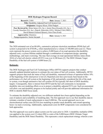
Table II. An example of features of some literature fuel cell models covered for thispaper.ModelsState1 SystemStudied phenomenaboundaryTheoretical approachSpringer et al. (1)SSFuel cellWater transportBernardi &SSCatalyst layer Cell polarization, water transportVerbrugge (2)and catalyst utilization.Fuller & NewmanSSFuel cellHeat & water management and(3)fuel utilization.Nguyen & White (4) SSGas channels Heat & water managementYi & Nguyen (11)SSFuel cellHeat & water management,species transportHeat & water managementDannenberg et al.SSFuel cell,(21)along-thechannelYou & Liu (28)SSCathodeTransport & flow in gas channelscatalyst layer & gas diffusersBoettner et al. (31)SSFuel cellSystem & system componentsystemperformance and controlstrategiesSemi-emp. approachKim et al. (5)SSFuel cellEmpirical cell polarizationequationAmphlett et al. (7)TRFuel cell stack Heat managementMann et al. (20)SSFuel cellGeneric modelNOTE: 1) SS steady-state, TR transientCommercial Fuel Cell SoftwareRe-creating and validating models from the literature can be time consuming, makingready-to-use models an attractive option when time is limited. A few commercial fuel cellmodels and additional software modules are available, e.g., Emmeskay, ADVISORTM2002 from the National Renewable Energy Laboratory (NREL), GCTool (GeneralComputational Toolkit) from Argonne National Laboratory (ANL), the fuel cell modulesin Easy 5 from Ricardo, and FEMLAB from COMSOL (32-37). More commercialmodels are being developed, especially multi-dimensional models. For example, AnsoftCorporation and Synopsys (formerly Avant!) will make PEM fuel cell system modelsavailable in the near future, and Fluent and CD adapco Group will soon release CFDPEM fuel cell packages (38, 39).Figure 1 shows a selection of fuel cell models available in literature andcommercially. The figure provides a systematic overview of the collected fuel cellmodels. If a more detailed and complex fuel cell model is desired, the user should look on
ady-state/Quasi Steady-stateTransientSteady-state &TransientLLiterature modelCCommercial softwareC1 EmmeskayC2 GCToolC3 ADVISORTM 2002C4 Easy5 fuel cell packageC5 FEMLAB fuel cell packageC6 FluentC7 Star-CD fuel cell tialDimensionSpringer et al., 1991 (ref. 1)Bernardi & Verbrugge, 1992 (ref. 2)Fuller & Newman, 1993 (ref. 3)Nguyen & White, 1993 (ref. 4)Kim et al., 1995 (ref. 5)Weisbrod et al., 1995 (ref. 6)Amphlett et al., 1996 (ref. 7)Thirumulai & White, 1997 (ref. 8)Wöhr et al., 1997 (ref. 9)Broka & Ekdunge, 1997 (ref. 10)Yi & Nguyen, 1998 (ref. 11)Xue & Dong, 1998 (ref. 12)Gurau et al., 1998 (ref. 13)Eikerling et al., 1998 (ref. 14)Virji et al., 1998 (ref. 15)Lee & Lalk, 1998 (ref. 16)Yi & Nguyen, 1999 (ref. 17)Squadrito et al., 1999 (ref. 18)Um et al., 2000 (ref. 19)Mann et al., 2000 (ref. 20)Dannenberg et al., 2000 (ref. 21)Gurau et al., 2000 (ref. 22)Cownden et al., 2001 (ref. 23)Hamelin et al., 2001 (ref. 24)Eaton et al., 2001 (ref. 25)Maggio et al., 2001 (ref. 26)Kulikovsky, 2001 (ref. 27)You & Liu, 2002 (ref. 28)Berning et al., 2002 (ref. 29)Pisani et al., 2002 (ref. 30)Boettner et al., 2002 (ref. 31)Figure 1. An overview of fuel cell models available in literature and commercially.
the upper half of the figure. If the user is looking for a fuel cell system model, the boxdefined by the “0-D” and “Semi-empirical” axis labels is a good starting point.Table III gives a more detailed view of the commercial fuel cell models describedbelow. The information about the upcoming fuel cell modules from Fluent and CDadapco Group (shown in Figure 1) is not sufficient for this more detailed comparison.Therefore, the two models are not included in Table III. Details of the software featuresshown in Table III were found in vendor information, demonstration kits, softwaremanuals, and so forth. Information about the models varies greatly and changes overtime. The details in Table III should therefore be seen as the state-of-the-art as of the timethis paper was written.Table III. An overview of some commercial fuel cell software (the assessment of themodels refers to the specific fuel cell modules of the software packages).ModelEmmeskay LRicardoCOMSOLDimension00002State Transient SteadystateSystem boundary Cell Stack SystemApproach Theoretical SemiempiricalFixed & variable N/Atime step optionComplexityHighMediumMed./highLowMedium Cell/stackN/AMed./highMed./highMediumN/A SystemGraphical representationLibrary Documentation N/A not availableThe Emmeskay fuel cell model is a zero-dimensional fuel cell stack software package.The model is based on the MathWorks graphical simulation code Simulink. It can runfixed and variable time steps and can run in a real time mode. The fuel cell stack in thismodel is modeled as a “black box,” using a MATLAB S-function to link to a compiledproprietary source code. It features details such as water transport across the membrane,water condensation and evaporation, and transfer of the heat generated due to reaction.One special advantage of this model is that it includes pressure dynamics. The cathode
and anode pressures are controlled via a PI-controller that controls the cathode and anodeoutlet mass flow rates. The cathode outlet temperature is also controlled via a PIcontroller that regulates the coolant mass flow. Having the feature of pressure dynamicsenables evaluation of different fuel cell system control strategies. However, littleinformation on the calculation details of the fuel cell is available because they areproperty to Emmeskay.Two empirically based steady-state fuel cell system models are integrated intoNREL’s publicly released vehicle analysis software ADVISORTM 2002. ADVISORTM iswritten in MathWorks MATLAB and Simulink. One model simply simulates the fuel cellsystem via maps with characteristic system efficiency as a function of system net poweroutput. An assumption is that the fuel cell system can provide a specified net power whileconsuming a set amount of fuel independent of the complexity of the system.The second ADVISORTM 2002 fuel cell system model has a similar approach exceptthat its fuel cell performance is based on a polarization curve, the associated fuel use percell, and the number of individual cells within the stack. The auxiliary system (e.g.,compressor, fuel pump, and cooling fans) can be specified separately from the fuel cellstack and is composed of component maps. The system efficiency/power maps andpolarization curves included in the public release, specific for fuel cell stacks of a certainsize and power output, were provided by ANL and UTC Fuel Cells (formerly IFC).One drawback of the two ADVISORTM 2002 models is that thermal and watermanagement is not included. The heat interaction between the fuel cell system and therest of the vehicle cannot be displayed. Furthermore, sub-models of system componentssuch as reformer and compressor are not included. The two models are displayed as“ADVISORTM 2002” in Table III. A third fuel cell system model, GCTool from ANL, isincluded in ADVISORTM 2002 as a co-simulation option. Depending on the user’sspecific interests, any one of these three models can be used in ADVISORTM to representthe fuel cell interaction with the rest of the vehicle.GCTool was one of the first fuel cell software packages publicly available. Developedand maintained by ANL, it is a sequential model programmed in a C-based language. Itcontains models of different types of fuel cells and system components such as reformers,condensers, pumps, and nozzles. The user designs system configurations of variouscomponent models, which are interconnected by defined flows. Steady-state and dynamicsimulations can be performed. GCTool has its own thermodynamic property library,which was one of its major advantages when first released. The GCTool softwarepackage includes a manual and examples of how to use the software.The fuel cell package in Easy5 of Ricardo is similar to GCTool. Both GCTool andEasy5 are block-based fuel cell system simulation software packages, although Easy5displays information for each block in a more accessible way. Like GCTool, Easy5 has adatabase containing various system components displayed as blocks that can be arrangedin multiple ways. The database includes system components such as fuel cell stack,reformer, gas clean-up, and electric and control devices. It also contains thermal and fluidsystems models. An advantage of Easy5 is the capability for systems optimization andcomponent sizing. However, in contrast to GCTool, it does not include a thermodynamicproperty library.
A more detailed fuel cell model is provided in the Chemical Engineering Module ofFEMLAB. FEMLAB uses the MathWorks simulation code MATLAB. Here, the PEMfuel cell is a steady-state two-dimensional model. For even more detailed studies, threedimensional models of individual cell components (e.g., the cathode) are also available.The Chemical Engineering Module offers detailed modeling, including heat and masstransfer phenomena in the fuel cell. One benefit of this package is the post-processingand visualization of the results. It is accompanied by a manual and tutorial.CHOOSING FUEL CELL MODELS: AN NREL EXAMPLENREL’s Model SelectionAs previously discussed, the three existing fuel cell system models in ADVISORTM2002 provide tools for evaluating fuel cell vehicles. However, NREL decided that fuelcell system models with more flexibility and details were needed. NREL’s simulationobjective was to provide a tool for more detailed studies such as parametric studies,component sizing, and optimization. With a robust stand-alone fuel cell system model,system parameters such as cell temperature, cell pressure, and stoichiometric coefficientsfor the anode and cathode flows can be optimized.The aim was also to integrate the fuel cell system model into ADVISORTM so thateffects of the auxiliary system on the fuel cell system power output and on the rest of thefuel cell vehicle are taken into account. Hence, integrating the model into ADVISORTMenables the results to be displayed in a vehicle context (e.g., fuel economy, vehicle mass,acceleration, grade tests, and multiple drive cycles).One of NREL’s constraints was time (limited to about six months); this made readyto-use models attractive. Both discrete and continuous analysis of the system wasanticipated. Among the issues to be addressed by simulation were thermal and watermanagement and start-up requirements. In addition to using the criteria discussed in theModel Selection Criteria section of this paper, NREL wanted a model based onMATLAB/Simulink to facilitate implementation into ADVISORTM.Comparison of Two Fuel Cell System ModelsNREL decided to evaluate two models that were recently made available: the VirginiaTech (VT) model and the Royal Institute of Technology (KTH) model. The two fuel cellsystem models share similar features. They are zero-dimensional models based onMATLAB/Simulink and have open source codes. They combine empirical componentdata maps with theoretical models to predict performance and thermal and watermanagement. In Figure 1, the two models would be located in the lower left box of thematrix (semi-empirical, zero-dimensional).
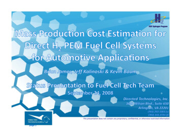
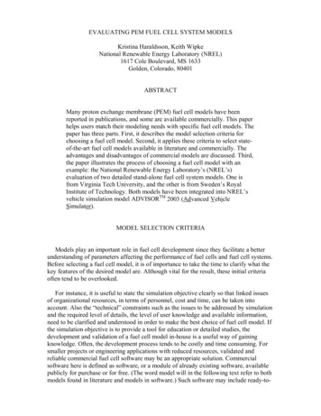
VT Fuel Cell System Model. The VT fuel cell system model (Figure 2), developed byVirginia Tech in collaboration with NREL, consists of a fuel cell model and an auxiliarysystem model (40). It is a transient, semi-empirical model that accounts for the thermalmanagement and water balance in the system. The fuel cell model is a polarization curvebased on a specific fuel cell stack available to VT. Its compressor model uses maps withdata from Opcon Autorotor (41).The model is designed for incorporation into ADVISORTM 2003. The goals of themodel are to provide hot- and cold-start effects on vehicle fuel economy, powerlimitations due to temperature, and a water balance for reactant humidification. Thefollowing are examples of the model’s inputs (constants and parameters): Number of cells and active cell areaStoichiometric coefficients of anode and cathode inlet flowsAir compressor and pump characteristicsMinimum cell voltage and current densityMaximum coolant temperatureConstants: open circuit voltage, heat capacities, molecular weights, density andspecific heat ratio of air, lower heating value of hydrogen, and so forthInitial conditions: temperatures of the ambient air, reservoir, radiator, cathode outlet,compressor outlet, humidifier outlet, inlet coolant; ambient pressure and humidity;minimum coolant mass flow rateCondenser percentage recoveryH2 HumidificationChamberFrom TanksDomeLoadedPressure RegulatorAir In Water InjectionHumidificationWater ReservoirAirCompressorH2 InletAir inAir outFuel Cell StackFuelAirDe-ionized WaterAir HumidifierThermostatBypassMain Thermal PumpRadiatorReservoirFuel SystemAir SystemThermal SystemFigure 2. The VT fuel cell system model (40).Outputs of the VT model are net power output from the fuel cell system and systemcharacteristics. The system characteristics include auxiliary system power requirements(e.g., air compressor, condenser fan, and coolant pump), mass flows at various points,heat losses, water generation, water balance, cell voltage, and current. An example of the
System Efficiency [%]impact of the fuel cell system operating temperature on the system efficiency is shown inFigure 3.Increasingtemperature605080 C0C4030Limited powerdue to minimumcell voltage criteria201000100002000030000400005000060000System Net Power [W]Figure 3. An example of output of the VT fuel cell system model: the system efficiencyas a function of the system net power and fuel cell system operating temperature.An example of the fuel cell system in a vehicle context is provided in Figure 4, wherethe output from the VT fuel cell system model integrated into ADVISORTM 2003 isdisplayed. The figure shows an efficiency comparison between hot- and cold-start modeson a highway drive cycle. There is a clear cold-start penalty, shown as lower systemefficiency and as longer time for reaching the fuel cell operating temperature. Thisparticular drive cycle normally runs with hot start.System EfficiencyTemperature100System Efficiency [%]9034380333Cold Start Temperature70Hot StartEfficiency60Cold StartEfficiencyDrive Cycle Speed 600Fuel cell temperature [K]353Hot Start Temperature700Time [s]Figure 4. An example of output from the VT fuel cell system model integrated intoADVISORTM 2003: the system efficiency comparison between hot and cold start modeson the U.S. EPA Highway drive cycle.
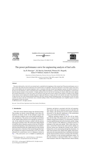
KTH Fuel Cell System Model. The KTH fuel cell system model (Figure 5) sharessimilar features with the VT model. It is a semi-empirical model with thermal and watermanagement (42). However, the KTH model is a steady-state model. Furthermore, thefuel cell stack component of the model is theoretical, partly based on work by Springer etal. (1) and accounts for phase changes of the water in the fuel cell stack. The model’stheoretical approach allows for stack definition, i.e., calculation of the number of cellsbased on the required maximum power output of the system. With assumptions of activearea and stoichiometric coefficients of hydrogen and air, it could be used for any fuel cellstack, giving the model a significant flexibility.The auxiliary system includes a hydrogen tank and power demand calculations forindividual pumps and fans. It also contains maps with compressor data from OpconAutorotor. The system allows hydrogen to be re-circulated and allows for the waterproduced in the stack to be condensed and used in the humidifiers. Heat produced in thefuel cell stack is transferred to a cooling loop. The model also accounts for frictionallosses found in lines, elbows and filters.AirFilterRadiatorMRe-circulation of H 2OACathodeAir, H2OHumidifierExhaustCondenserDC (to thepropulsionmodule)H2 (g) fromtankAnodeHumidifierH 2, H 2OCondenserFuel cell stackPurgeRe-circulation of H 2FilterCooling waterFigure 5. The KTH fuel cell system (42).Inputs for the KTH model are similar to those for the VT model. Examples of uniquefeatures include the purge percentage (the amount of the anode exhaust to be removedfrom the system) and pipe diameter and length.The model outputs are the net fuel cell system power, the stack definition, and systemcharacteristics such as mass flow of the reactants, product, inert material and coolant,heat developed in the stack, individual auxiliary parasitic loads, water balance of the fuelcell system (including humidifiers and condensers), and the efficiency of the fuel cell andsystem.
An example of the results of the KTH fuel cell system model integrated intoADVISORTM 2003 is provided in Figure 6. A small fuel cell vehicle of about 1000 kgusing the fuel cell system power output of 48 kW and 43% at peak load is simulatedusing the U.S. EPA Highway drive cycle. The upper diagram shows the drive cycle speedspecification and vehicle speed in miles per hour (mph). The three diagrams belowdisplay the impact of the auxiliary system on the net fuel cell system power output. Thefirst of these diagrams displays net system power achieved during the cycle. The diagrambelow shows the variation of the auxiliary system power demand, including those of thecompressor, pumps, and fans. The major component of the auxiliary system power load isthat of the compressor, and its power demand is also shown in the diagram. The variationin the fuel usage during the drive cycle is shown in the diagram at the bottom of thefigure.Figure 6. An example of the KTH fuel cell system model integrated into ADVISORTM2003 using the U.S. EPA Highway drive cycle to simulate the load of a small fuel cellvehicle.
DISCUSSIONTable IV compares the VT and KTH fuel cell system models. Although they havesimilar features (e.g., dimension, system boundary, and environment), there are distinctdifferences. For instance, the fuel cell model approach of the KTH model departs fromthe VT model in the details of the electrochemistry. The KTH model has a moretheoretical and more general
reliable commercial fuel cell software may be an appropriate solution. Commercial software here is defined as software, or a module of already existing software, available . current density distribution, voltage, and pressure drops in the fuel cell stack. If a tool for education or detailed studies is desired, a fuel cell model with a .