Transcription
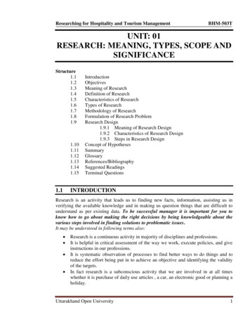
RESEARCH AN(i; DEVELOPMENl jN.CINCLUDINGThe RevolutionaryBASE ANTENNASNEW MOBILE ANTENNASNEW MARINE ANTENNASMOBILE ACCESSORIES40 CHANNEL ENGINEEREDFOR LONG DISTANCECOMMUNICATION
a research ana developmentcompany dedicated to qualityand performancein C.B. antennasAll AvantiAntennasMada InThe U S.A.
(I CO-INDUCTIVE llTHEAVANTI CO-INDUCTIVE PRINCIPLEOne of the most common antenna types used in the C.B. field is the Yagi-Uda array, ormore simply the Yagi. It derives it’s name from the professors who first promoted its use.This type of beam antenna consists of a dipole as a driven element and other dipoleparasitic elements that are inductively coupled to the driven element. This is a “supergain" design which indicates that it furnishes a very high gain in relation to its size.Although the Yagi features a “super gain” for frontal signals, it leaves something to bedesired in back rejection (the ability to reject unwanted signals from the back of theantenna). Depending on how much one is willing to sacrifice on gain, the back rejectioncan be increased nominally. If the elements are adjusted for maximum gain the backrejection suffers.If instead of using a driven element, all elements of a beam antenna are fed (connectedto the coaxial line), it is possible to achieve a very good back rejection but the qain ispoorer than a Yagi.One antenna type that has been developed on the AVANTI test range is the ASTROPLAN E,which has been granted U.S. Patent #3587109. This antenna develops an intense electricalfield if the bottom, skirt section, is excited minus the top monopole. If the top monopoieis short, little energy is coupled to it. As the monopole is made increasingly longer, moreenergy is coupled. If the element is made 10% shorter than a quarter wave length, a verystrong CO-INDUCTIVE effect is formed between the two elements.The ASTROBEAM antenna is another good example of co-induction. The ASTROBEAM isformed by combining an ASTROPLANE as a driven (fed) element of an array of dipoleswhich form a director and a reflector. In this design combination the phenomenon ofCO-INDUCTION is extended to encompass all of these elements. The CO-INDUCTIVEeffect creates such a phase and magnitude in the parasitic elements that the antennaelements act as though they were directly driven and an unusually high back rejection,greater than 40 db, is achieved. In addition, this effect keeps the antenna “super gain”with the result that gains are achieved that surpass the best designed Yagis.The ASTROBEAM incorporates these advantages in an antenna that utilizes a dipole asa reflector, which is consistent with the traditional design of Yagi antennas.Experiments have shown that even higher front to back ratios can be achieved with aquad reflector as used in the MOON RAKER. This reflector is really two half waveelements back to back. They are arranged with a V2 wave-length “V” and a similar "V”directly opposing it. This means that there are two fields available to couple the drivenelement and the greater back rejection demonstrates that a CO-INDUCTiVE field exists tofurnish optimum phase and magnitude to the combination of the driven and “quad”elements.The AVANTI principle of CO-iNDUCTION is demonstrated by the omni-directionalperformance of the ASTROPLANE and the directional efficiency of the ASTROBEAM,PDL-II and MOONRAKER antennas. It Is this use of the novel coinductive principle thatenables Avanti to offer its customers antennas of unusual design and very highperformance.E \\?uyYiCo-inductive. Astro plane, Sigma 5/S Astro Beam, Saturn, Tri-Gamma, PDL l , Ramrod. Interceptor, Fazer, Racer, Gatorwhip, Hippo,Ocean Racer are trademarks and Avanti and Moonraker are registered tremarks of Avanti Research & Development, Inc., Addison Illinois.
YOU SHOULD KNOW THESE.[ WlitTffl FACTS ABOUT C.B. ANTENNASFrom time to time, many CBer's are heard to make the remark that a particular antenna is not living up to theadvertised performance figures such as gain, S.W.R,, or front-to-back ratio- These statements are usuallyfounded on their personal field tests; often based on comparisons between one antenna and another. The dis parity between the tests of the CBer and the factory usually stems from the conditions under which the testswere run. The following is a short discussion of some of the variable conditions that do occur and how theyaffect antenna performance.EFFECT OF OTHER ANTENNAS — When two antennas are mounted near each other (even if they are used fordifferent frequencies), a coupling usually results which in some way alters their operation. This coupling is evenmore pronounced when the antennas are mounted less than one wavelength apart. So, if another antenna isless than 36 feet from your CB antenna, there is a good chance that it changes its performance in some way.THE EFFECT OF METAL STRUCTURES — Not only antennas, but water towers, power tines, buildings, or anymaterial of a conductive nature has the ability to misdirect transmission. Sometimes these obstacles will act asdirectors and sometimes as reflectors — causing the signal to increase or decrease in the intended direction.Complaints of poor front-to-back ratio or lower than expected gain can usually be traced to this above circum stance — especially in beam-type operation.SIGNAL INTENSITY — The signal strength of a remote transmitting station can never be assumed to be of thesame strength as in previous transmissions. Signals of incoming stations should be recalibrated to the antennasbeing compared. For this reason, you cannot take down one antenna, put up another one a week later, and expectto make accurate measurements. If the stations being used are using beam type antennas, a slight change in thebeams' direction can also be critical. Contacts with mobiles are even less valid. A movement of five feet some times makes measureable differences in mobile communications,5 METER CALIBRATION — Depending upon the CB set, an S meter is calibrated so that one S unit is equal to6 db. Therefore, an antenna responsible for 1 S unit gain over another has also about 6 db over that other antenna.Some S meters, however, are calibrated at only 3 db per S unit and others at 3 or 4 at the low end, and 6 or 7 atthe top of the scale.Another problem encountered with S meters is the inability to measure high strength inputs. Some bounce backat a powerful signal and appear erratic in operation even reading lower on the scale with an increased signal.COAX AND CONNECTORS — The quality of the coax and connectors and especially the soldering of the coaxto the connector can affect S.W.R. and gain. Many times an unsuspecting CBer will buy a low grade coax andlose 2 or 3 db after paying good money for an expensive transceiver and antenna. A quick check for good coaxand connections can be run by substituting a dummy load on the antenna end of the coax. If all is right, theS.W.R. with the dummy load should be a 1 to 1 match.CRYSTAL VARIATIONS — Mr. A and Mr. B are neighbors and they are comparing the performance of theirantennas by their ability to transmit to Mr, C about 20 to 30 miles away. If Mr. A has a crystal slightly high onfrequency, he might show a weaker signal to Mr. C even though his operation has more power: This would makeA’s antenna seem inferior to B's. This problem can be eliminated by Mr. C’s having a tunable receiver on histransceiver to match A’s variation.ANTENNA HEIGHT — Whenever antennas are being compared, they should be installed at the proper distanceabove the ground and preferably in an open field. This operation is not even legal for CB’ing when using a hori zontal beam because the proper distance above ground for this mode of transmission is 36 feet or more. Onlythe test of a vertical antenna may be run at a legal height of 60 feet in an open field.TIME VARIATION — Any test of antennas should be performed with a time variation of about 15 minutes or lessto eliminate variations due to tropospheric shifts and other changes that affect performance.GUY WIRES AND SUPPORTING STRUCTURES — Guy wires should preferably be of the non-metallic type usingski tow rope or other plastic lines. If metallic guy wires are used, they should be broken up at uneven intervalsalong their length to avoid interference and possible high S.W.R In many cases, a manufacturer intends hisantenna to be mounted on a metal mast of tower and in some cases, the mast or tower is used as a radiatingelement.PROPER CONSTRUCTION — If they could, manufacturers would ship ail antennas fully assembled In order toeliminate mistakes in construction often found in antenna installations. Even the best instructions are some times mis-read and an antenna condemned only because of an error in assembly. If an antenna does not performup to par, contact your local distributor or dealer, and if he can’t help you, call the manufacturer. Chances arethat somebody will get it working.These are by no means all of the possible variations to consider in antenna measurements; however, they aresome of the most important and understanding them will certainly be to the CBer’s benefit and may save timein finding a trouble source.ANTENNA ELECTROCUTIONS — Great care should be exercised in installing any antenna to avoid contact withelectrical wires. Assume any overhead lines to be a potential electrocution hazard! t IMPORTANT SAFETY NOTICE — Any AVANTI base station antenna is designed to be grounded to the supportmast using the mounting hardware provided. Grounding of the mast can “bleed off” static. Be sure your antennamast tripod or tower are properly grounded. Consult the National Electrical Code, your local CB dealeror installation experts for installing a good, safe ground for your location.3
0AMMV\\ASTRO BEAMModel AV-150Increased Coupling Makes It . . . the most efficient beam antennaavaitable to the CBfer. We started with our famous Astro Plane(patented) as a radiator, then added a reflector and a director toachieve the beam configuration. The Astro Plane has more gain(4.46 db) to begin with than a dipole which is commonly used asthe radiator of a beam and it couples to the director and thereflector more efficiently. This close coupling efficiency results Inan unprecedented 40 db front-to-back ratio.This three element beam is made with an ASTRO PLANE antennaas a driven element, rather than a simple half wave unify gain dipole.The ASTRO PLANE is uniquely suited for the purpose — no radialsto interfere with the other elements, 4.46 db gain, and the abilityto radiate from the top make it a natural choice.Because its unusual design allows it to be fitted over the supportmast, it allows optimum spacing for gain as well as perfect mech anical balance.The elements are made from aircraft quality aluminum tubing, as isthe boom, while the hubs are molded of high strength weatherresistant Cycolac, These molded hubs feature a pin lock designwhich aligns the elements* This feature also keeps the elementsfrom twisting once they are up in the air — a problem oftenencountered with beams. The weight of this antenna is only 14lbs. so it can easily be rotated by an inexpensive TV rotor withoutgoing to the more costly models.A 40 db rejection means that if a signal is coming in at a certainstrength and the ASTRO BEAM is turned around so that the backis toward the signal, the signal will drop 40 db or more. See PolarPlot Graph.Forward gain of 11 db over an isotropic source is a means of ratingthe antenna's ability to increase, receive and transmit signals. Thepoint here is that the ASTRO BEAM has about 1 db more than thebest 3 element beam currently on the market. This gain has theequivalent of multiplying your power about 12.5 times .SPECIFICATIONSRejection—40 db signal drop front-to-backForward Gain—11 db over an isotropic sourceImpedance—50-52 ohmsV.S.W.R.—1.3:1 or lessBoom length—IOV2 feet, Weight—14 lbs.Mode—Vertical BeamTurning Radius—63 inchesMaterial—Aluminum & Cycolacimpedance—50-52 ohmsLight to Medium duty rotor neededPower Multiplication 12.6XWind Load Area — 2.6 sq. ft.Actual Astro Beam Polar plotShows Signal af 41 db PowerLevel Reduced to Almost 0 dbon Bach of Antenna, Graph ShowsSignal Level. Do Not Confusewith Gain. 40 db Is About 7 "s"Units on Most Receivers.Patented andmade onlyby AVANTINOTE: Not available as cowersion kit tor Astro Plane.CO-INDUCTIVE4
* SIGMA 5/8 Model AV-170SIGMA 5/8 is full 22 tall 5/8 wave groundplane designed to give strong, noise-freelong distance performance. An efficientmatching loop, which prevents burn outs anddetuning, eliminates the need for coils ortransformers. The radiator is adjustable forfine tuning and pre-marked for easy “nomeasuring” assembly. This telescoping sec tion uses full circle clamps for positiveelectrical contact and sturdy construction.The sturdy heavy-duty radials have stainlesssteel tips for reduced wind loading. Con struction is all heavy wail aircraft qualityaluminum, aluminum castings, stainless steeland fiberglass.SPECIFICATIONS* Gai n5.14 db over isotropic4,17 db over Va wave ground plane3.00 db over Vz dipoleV,S,W.R. 1.3:1 or lessPower Multiplication Factor—3.3Impedance—50-52 ohmsOmnidirectional—no rotor neededHeight—22 feetRadials—9 feetWeight—9 lbs.*NOTE: In an effort to clean up the use ofmisleading gain claims, AVANTi lists 3 ratings(over % wave ground plane, over isotropic source,and over dipole). If these figures are comparedto other antennas of the same type, care mustbe taken to see what reference is being used NO COILS MEAN LESSNOISE, MORE POWER TUNABLE RADIATORMEANS LOWER S.W.R. HIGH QUALITYCONSTRUCTION MEANSLONG LIFEModel AntennaNot To ScaleEr5
ASTRO PLANEANTENNA, Mode! AV 1016 Good Reasons Why the Revolutionary AVANTlASTRO PLANE is the best omni-directional C.B.Antenna you can buy1. It has top radiation which means that your signalgets out from the highest part of your antenna.This is especially important where antenna heightis limited as in C.B. radio because your signalra
One antenna type that has been developed on the AVANTI test range is the ASTROPLAN E, which has been granted U.S. Patent #3587109. This antenna develops an intense electrical field if the bottom, skirt section, is excited minus the top monopole. If the top monopoie is short, little energy is coupled to it. As the monopole is made increasingly longer, more energy is coupled. If the element is .