Transcription
Downloaded from https://www.atecorp.com/The documentation and processconversion measured necessaryto comply with this revision shallbe completed by 3 July 2012.INCH–POUNDMIL–STD–750F3 January 2012SUPERSEDINGMIL–STD–750E20 November 2006DEPARTMENT OF DEFENSETEST METHOD STANDARDTEST METHODS FOR SEMICONDUCTOR DEVICESAMSC N/AFSC 5961
Downloaded from https://www.atecorp.com/MIL–STD–750FFOREWORD1. This test method standard is approved for use by all Departments and Agencies of the Department of Defense.2. This issue of MIL–STD–750 series establishes uniform test methods for testing the environmental, physical, andelectrical characteristics semiconductor devices.3. This entire test method standard has been revised. This revision has been issued in six parts; the basic testmethod standard (this document) and five numbered parts. This was done in order to provide flexibility in the use andthe updating of the test methods. The six parts are listed as ��––––MIL–STD–750–5–Test Methods For Semiconductor Devices.Environmental Test Methods For Semiconductor Devices.Mechanical Test Methods For Semiconductor Devices.Electrical Characteristics Tests for Bipolar, MOSFET, and Gallium Arsenide Transistors.Electrical Characteristics Tests for Diodes, Microwave Diodes, Thyristors, and TunnelDiodes.High Reliability Space Application Test Methods For Semiconductor Devices.4. Comments, suggestions, or questions on this document should be addressed to: Commander, DefenseLogistics Agency, DLA Land and Maritime, ATTN: VAC, P.O. Box 3990, Columbus, OH43218–3990, or emailed to semiconductor@dla.mil. Since contact information can change, you may want to verifythe currency of this address information using the ASSIST Online database at https://assist.daps.dla.mil.ii
Downloaded from RAGRAPHPAGEFOREWORD. . . .ii1.SCOPE . 11.1Purpose . 11.2Numbering system . 11.2.1Classification of tests . 11.2.2Test method revisions . 11.3Methods of reference . 12.APPLICABLE DOCUMENTS . 22.1General . 22.2Government documents . 22.2.1Specifications, standards, and handbooks . 22.3Non-Government publications . 22.4Order of precedence . 33.DEFINITIONS . 33.1Acronyms, symbols, and definitions . 33.1.1Acronyms used in this standard. 34.GENERAL REQUIREMENTS . 44.1Test conditions . 44.1.1Permissible temperature variation in environmental chambers . 44.1.2Electrical test frequency . 54.1.3Accuracy . 54.1.3.1Control based on uncertainty . 54.1.3.2Test methods and circuits . 64.1.4Calibration requirements . 64.2Orientations . 64.3General precautions . 84.3.1Transients . 84.3.2Test conditions for electrical measurements . 84.3.2.1Thermal resistance measurements (test method series 3100) . 84.3.2.2Low frequency tests (test method series 3200) . 84.3.2.3High frequency tests (test method series 3300) . 84.3.2.4Electrical characteristics tests for MOS field effect transistors (3400 series) . 84.3.2.5Steady-state dc measurements (test method series 4000) . 84.3.2.6Pulse measurements (test method series 4000) . 84.3.2.7Electrical characteristics tests for microwave diodes (test method series 4100). 94.3.3Test circuits . 94.3.3.1Test method variation . 94.3.4Soldering . 94.3.5Order of connection of leads . 94.3.6Radiation precautions . 94.3.7Handling precautions . 104.3.7.1UHF and microwave devices . 104.3.7.2Electrostatic discharge sensitive devices . 104.4Continuity verification of burn-in and life tests . 104.4.1Bias interruption . 104.5Requirements for high temperature reverse bias (HTRB) and burn-in . 114.6Bias requirements . 114.7Destructive tests . 124.8Non–destructive tests . 134.9Laboratory suitability . 144.10Recycled, recovered, or environmentally preferable materials . 14iii
Downloaded from RAGRAPHPAGE5.5.15.25.3DETAILED REQUIREMENTS. 14Organization . 14Arrangement and contents . 14References to MIL–STD–750 . 146.6.16.26.36.4NOTES . 14Intended use . 14International standardization agreement . 14Subject term (key word) listing . 15Changes from previous issue . 15FIGURE1.2.TITLEPAGEOrientation of noncylindrical semiconductor device to direction of accelerating forceError! Bookmarknot defined.Orientation of cylindrical semiconductor device to direction of accelerating forceError! Bookmark notdefined.CONCLUDING MATERIAL . . .15iv
Downloaded from https://www.atecorp.com/MIL–STD–750F1. SCOPE1.1 Purpose. This standard establishes uniform methods and procedures for testing semiconductor devicessuitable for use within Military and Aerospace electronic systems. The methods and procedures in the various partsof this standard cover basic environmental, physical, and electrical tests to determine resistance to deleterious effects ofnatural elements and conditions surrounding military and space operations. For the purpose of this standard, the term"devices" includes such items as transistors, diodes, voltage regulators, rectifiers, tunnel diodes, and other relatedparts. This standard is intended to apply only to semiconductor devices. The test methods and proceduresdescribed in the various parts of this multipart test method standard have been prepared to serve several purposes:a.To specify suitable conditions obtainable in the laboratory that give test results equivalent to the actualservice conditions existing in the field and to obtain reproducibility of the results of tests. The test methodsdescribed by this standard are not to be interpreted as an exact and conclusive representation of actualservice operation in any one geographic location since it is known that the only true test for operation in aspecific location is an actual service test at that point.b.To describe, in a series of standards, all of the test methods of a similar character which now appear in thevarious joint-services semiconductor device specifications so that these test methods may be kept uniformand thus result in conservation of equipment, man-hours, and testing facilities. In achieving this objective, itis necessary to make each of the general test methods adaptable to a broad range of devices.c.The test methods described by this standard for environmental, physical, and electrical testing ofsemiconductor devices shall also apply, when applicable, to parts not covered by an approved militarysheet-form standard, specification sheet, or drawing.1.2 Numbering system. The test methods are designated by numbers assigned in accordance with the followingsystem.1.2.1 Classification of tests. The test methods are divided into five areas and are contained in five parts of thismultipart test method standard. Test methods numbered 1000 to 1999 inclusive, cover environmental tests and arein MIL–STD–750–1. Test methods numbered 2000 to 2999 inclusive, cover mechanical- characteristics tests and arein MIL–STD–750–2. Electrical- characteristics tests are covered in two groups; 3000 to 3999 inclusive, cover testmethods for transistors (see MIL–STD–750–3) and 4000 to 4999 inclusive, cover test methods for diodes (seeMIL–STD–750–4). Test methods numbered 5000 to 5999 inclusive, are for high reliability space applications and arein MIL–STD–750–5.1.2.2 Test method revisions. Test method revisions are numbered consecutively using a period to separate thetest method number and the revision number. For example, test method 1001.2 is the first revision of test method1001.1.3 Method of reference. Test methods contained in this multipart test method standard shall be referenced, whenapplicable, in the individual specification, specification sheet, or procurement documents by specifying the testmethod number and the details required in the summary of the applicable method. The basic standard shall bereferenced and not the individual part or parts of this standard (see 5.3). To avoid the necessity for changingdocuments that refer to this standard, the revision number of a test method should not be used when referencingindividual test methods. For example, use 1001 as a reference versus 1001.2.1
Downloaded from https://www.atecorp.com/MIL–STD–750F2. APPLICABLE DOCUMENTS2.1 General. The documents listed in this section are specified in sections 3, 4, or 5 of this standard. This sectiondoes not include documents cited in other sections of this multipart standard or recommended for additionalinformation or as examples. While every effort has been made to ensure the completeness of this list, documentusers are cautioned that they must meet all specified requirements documents cited in sections 3, 4, or 5 of thisstandard, whether or not they are listed.2.2 Government documents.2.2.1 Specifications, standards, and handbooks. The following specifications, standards, and handbooks form apart of this document to the extent specified herein. Unless otherwise specified, the issues of these documents arethose cited in the solicitation or contract.DEPARTMENT OF DEFENSE SPECIFICATIONSMIL–PRF–19500–Semiconductor Devices, General Specification for.DEPARTMENT OF DEFENSE l Test Methods For Semiconductor Devices.Mechanical Test Methods For Semiconductor Devices.Electrical Characteristics Test Methods for Bipolar, MOSFET, and Gallium ArsenideTransistor Semiconductor Devices.Electrical Characteristics Test Methods for Diodes, Microwave Diodes, Thyristors,and Tunnel Diode Semiconductor Devices.High Reliability Space Application Test Methods For Semiconductor Devices.Electrostatic Discharge Control Program for Protection of Electrical and ElectronicParts, Assemblies and Equipment (Excluding Electrically Initiated ExplosiveDevices).DEPARTMENT OF DEFENSE HANDBOOKSMIL–HDBK–263–Electrostatic Discharge Control Handbook for Protection of Electrical and ElectronicParts, Assemblies and Equipment (Excluding Electrically Initiated ExplosiveDevices)(Metric).(Copies of these documents are available online at https://assist.daps.dla.mil/quicksearch orhttps://assist.daps.dla.mil or from the Standardization Document Order Desk, 700 Robbins Avenue, Building 4D,Philadelphia, PA 19111-5094.)2.3 Non-Government publications. The following documents form a part of this document to the extent specifiedherein. Unless otherwise specified, the issues of these documents are those cited in the solicitation or contract.ASME INTERNATIONAL (ASME)ASME Y14.38–Abbreviations and Acronyms for Use on Drawings and Related Documents.(Copies of these documents are available online at http://www.asme.org or from ASME International, Three ParkAvenue, New York, NY 10016–5990.)2
Downloaded from https://www.atecorp.com/MIL–STD–750FNCSL INTERNATIONAL (NCSL)NCSL Z540.3–Requirements for the Calibration of Measuring and Test Equipment.(Copies of this document are available online at http://www.ncsli.org or can be obtained through NCSLInternational, 2995 Wilderness Place, Suite 107, Boulder, CO 80301–5404.)2.4 Order of precedence. Unless otherwise noted herein or in the contract, in the event of a conflict between thetext of this document and the references cited herein (except for related applicable specification sheet, the text of thisdocument takes precedence. Nothing in this document, however, supersedes applicable laws and regulations unlessa specific exemption has been obtained.3. DEFINITIONS3.1 Acronyms, symbols, and definitions. For the purposes of this standard, the acronyms, symbols, and definitionsspecified in MIL–PRF–19500, ASME Y14.38, and herein shall apply.3.1.1 Acronyms used in this standard. Acronyms used in this standard are defined as follows:a.BIST–Backward instability shock test.bCFM–Cubic feet per minute.c.DUT–Device under test.d.ESD–Electrostatic discharge.e.ESDS–Electrostatic discharge sensitivity.f.FET–Field-effect transistor.g.FIST–Forward instability shock test.h.GaAs–Gallium Arsenide.i.HTRB–High temperature reverse bias.j.Hz–Hertz.k.ICBO–Collector to base cutoff current.l.IGBT–Insulated gate bipolar transistor.m. LCC–Leadless chip carrier.n.mH–Microhenries.o.MOS–Metal oxide semiconductor.p.MOSFET –Metal oxide semiconductor field-effect transistor.q.NIST–National Institute of Standards and Technology.r.NPN–The doping regions of a particular type of bipolar junction transistor.3
Downloaded from osecond.t.pF–Picofarad.u.PIND–Particle impact noise detection.v.PNP–The doping regions of a particular type of bipolar junction transistor.w.RH–Relative humidity.x.SEM–Scanning electron microscope.y.SOA–Safe operating area.z.TSP–Temperature sensitive parameter.aa. UHF–Ultra high frequency.bb. VCB–Forward voltage drop of the collector.cc. VEB–Voltage drop of the emitter to base.dd. VSWR–Voltage standing wave ratio.4. GENERAL REQUIREMENTS4.1 Test conditions. Unless otherwise specified herein or in the individual specification sheet, all measurementsand tests shall be made at thermal equilibrium at an ambient temperature of 25 C 3 C and at ambient atmosphericpressure and relative humidity and the specified test condition C (at environmentally elevated and reducedtemperatures shall have a tolerance of 3 percent, or 3 C, whichever is greater). Whenever these conditions mustbe closely controlled in order to obtain reproducible results, the referee conditions shall be as follows: Temperature25 C 1 C; relative humidity 50 5 percent; and atmospheric pressure from 650 to 800 millimeters of mercury.Unless otherwise specified in the detail test method, for mechanical test methods, (series 2000), the ambienttemperature should be 25 C 10 C.4.1.1 Permissible temperature variation in environmental chambers. When chambers are used, specimens undertest shall be located only within the working area defined as follows:a.Temperature variation within working area: The controls for the chamber shall be capable of maintaining thetemperature of any single reference point within the working area within 2 C or 4 percent, whichever isgreater.The controls for the chamber shall be such that the temperature of any single reference point within the workingarea shall not deviate more than 2 C or 4 percent, whichever is greater.b.Space variation within working area: Chambers shall be so constructed that, at any given time, thetemperature of any point within the working area shall not deviate more than 3 C or 3 percent, whicheveris greater, from the reference point, except for the immediate vicinity of specimens generating heat.c.Chambers with specified minimum temperatures (such as those used in burn-in and life tests): When testrequirements involve a specified minimum test temperature, the controls and chamber construction shall besuch that the temperature of any point within the working area shall not deviate more than 8 C, –0 C; or 8percent, –0 percent, whichever is greater, from the specified minimum temperature, except for theimmediate vicinity of the specimens generating heat.4
Downloaded from https://www.atecorp.com/MIL–STD–750F4.1.2 Electrical test frequency. Unless otherwise specified, the electrical test frequency shall be 1,000 25 Hertz(Hz).4.1.3 Accuracy. The specified limits are for absolute (true) values, obtained with the specified (nominal) testconditions. Proper allowance shall be made for measurement errors (including those due to deviations from nominaltest conditions) in establishing the working limits to be used for the measured values, so that the true values of thedevice parameters (as they would be under nominal test conditions) are within the specified limits.The following electrical test tolerances and precautions, unless otherwise specified in the applicable acquisitiondocument, shall be maintained for all device measurements to which they apply (test methods series 3000, 4000 andother specified electrical measurements). Wherever test conditions are specified in the applicable acquisitiondocument to a precision tighter than the tolerances indicated below, the specified conditions shall apply and takeprecedence over these general requirements.a.Bias conditions shall be held to a tolerance of 3 percent of the specified value, except for breakdowntesting (see 4.1.3.c).b.Such properties as input pulse characteristics, repetition rates, and frequencies shall be held to a toleranceof 10 percent. Nominal values shall be chosen so that 10 percent variation (or the actual test equipmentvariation, if less than 10 percent) does not affect the accuracy or validity of the measurement of the specifiedvalue.c.Voltages and currents applied in breakdown testing shall be held to a tolerance of 1 percent of thespecified value(s).d.Resistive loads shall be 5 percent tolerance.e.Capacitive loads shall be 10 percent or 1 picofarad (pF) tolerance, whichever is greater.f.Inductive loads shall be 10 percent or 5 microhenries (µH) tolerance, whichever is greater.g.Static parameters shall be measured to a tolerance of 1 percent.h.Switching parameters shall be measured to a tolerance of 5 percent or 1 nanosecond (ns), whichever isgreater.4.1.3.1 Control based on uncertainty. Test processes that have complex characteristics are best performed andcontrolled by the application of uncertainty analysis. The overall uncertainty in a test, or measurement process, shallbe determined and impact of said uncertainty on the product parameter tolerance shall be taken into account. Themethods used for determining uncertainty shall be defined and documented. The method selected shall use any, orall, combination of the following forms:a.Arithmetic addition (linear): Normally produces an overly conservative estimate and reflects a highlyimprobable situation in which contributing errors are at their maximum limit at the same time and samedirection.b.Root sum square (RSS): Normally applied where errors tend to fit a normal distribution (Gaussian) and arefrom independent sources.c.Partial derivatives: Used where complex relationships exist.d.Monte Carlo simulation: Used in very complex situation where other methods are not easily applied or donot fit.5
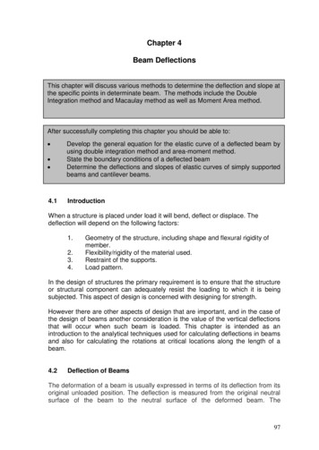
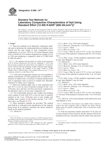
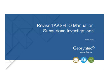
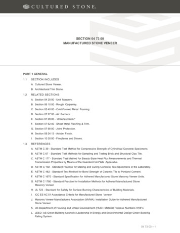
Downloaded from https://www.atecorp.com/MIL–STD–750Fe.Standard reference material (or controlled correlation device) testing providing observable data.NOTE: Observable data from a controlled device may be relied upon to provide feedback that confirmsprocess performance is within statistical limits.f.Analysis of systematic and random errors, applying corrections as applicable.g.Any other recognized method of combining errors into an expression of uncertainty substantiated by anengineering analysis.4.1.3.2 Test methods and circuits. Unless otherwise stated in the specific test method, the methods and circuitsshown are given as the basic measurement method. The methods and circuits shown are not necessarily the onlymethod or circuit which can be used, but the manufacturer shall demonstrate to the acquiring activity that alternatemethods or circuits which they may desire to use are equivalent and give results within the desired accuracy ofmeasurement (see 4.1.3).4.1.4 Calibration requirements. Calibration and certification procedures shall be provided in accordance withNCSL Z540.3 for plant standards and instruments used to measure or control production processes andsemiconductor devices under test. For those measurements that are not traceable to the National Institute ofStandards and Technology (NIST), correlation samples shall be maintained and used as the basis of provingacceptability when such proof is required. In addition, the following requirements shall apply:a.The accuracy of a calibrating instrument shall be at least four times greater than that of the item beingcalibrated, unless the item being calibrated is state of the art equipment, which may be near or equal inaccuracy to the state of the art calibrating equipment, in which case the four times requirement does notapply. However, the instrument shall be calibrated to correlate with standards established by the NIST.b.Except in those cases where the NIST recommends a longer period, and concurrence is obtained from thequalifying activity, calibration intervals for plant electrical standards shall not exceed one year and plantmechanical standards shall not exceed two years.4.2 Orientations.a.X is the orientation of a device with the main axis of the device normal to the direction of the acceleratingforce, and the major cross section parallel to the direction of the accelerating force.b.Y is the orientation of a device with the main axis of the device parallel to the direction of the acceleratingforce, and the principal base toward (Y1), or away from (Y2), the point of application of the acceleratingforce.c.Z is the orientation of a device with the main axis and the major cross section of the device normal to thedirection of the accelerating force. Z is 90 degrees of X.NOTE: For case configurations, other than those shown on figures 1 and 2, the orientation of the deviceshall be as specified in the individual specification sheet.6
Downloaded from https://www.atecorp.com/MIL–STD–750FFIGURE 1. Orientation of non-cylindrical semiconductor device to direction of accelerating force.FIGURE 2. Orientation of cylindrical semiconductor device to direction of accelerating force.7
Downloaded from https://www.atecorp.com/MIL–STD–750F4.3 General precautions. The following precautions shall be observed in testing the devices.4.3.1 Transients. Devices shall not be subjected to conditions in which transients cause the rating to be exceeded.4.3.2 Test conditions for electrical measurements. Unless otherwise required for a specified test method,semiconductor devices should not be subjected to any condition that will cause any maximum rating of the device tobe exceeded. The precautions should include limits on maximum instantaneous currents and applied voltages. Highseries resistances (constant current supplies) and low capacitances are usually required. If low cutoff or reversecurrent devices are to be measured; for example, nanoampere units, care should be taken to ensure that parasiticcircuit currents, or external leakage currents are small compared with the cutoff or reverse current of the device to bemeasured.4.3.2.1 Thermal resistance measurements (test method series 3100). For thermal resistance measurements, atleast three temperature sensitive parameters (TSP) of the transistor can be used; the collector to base cutoff current,ICBO; the forward voltage drop of the emitter to base diode, VEB; and the forward voltage drop of the collector tobase diode, VCB. The methods described in this test method standard refer to the thermal resistance betweenspecified reference points of the device. For this type of measurement, power is applied to the device at two valuesof case, ambient, or other reference point temperature, such that identical values of ICBO, VEB, or VCB are readduring the cooling portion of the measurement.4.3.2.2 Low frequency tests (test method series 3200). Unless otherwise specified, the measurements shall bemade at the electrical test frequency, 1,000 25 Hz. At 1,000 Hz, the reactive components may not be negligible.4.3.2.3 High frequency tests (test method series 3300). Care shall be taken that, in designing the circuit andtransistor mounting, adequate shielding and decoupling are provided and that series inductances in circuits arenegligible.4.3.2.4 Electrical characteristics tests for MOS field effect transistors (test method series 3400). Circuits areshown for n-channel field-effect transistors in one circuit configuration only. They may readily be adapted for pchannel devices and for other circuit configurations.4.3.2.5 Steady-state dc measurements (test method series 4000). Unless otherwise specified, all steady-state dcparameters are defined using steady-state dc conditions.4.3.2.6 Pulse measurements (test method series 4000). When device static or dynamic parameters are measuredunder pulsed conditions, in order to avoid measurement errors introduced by device heating during the measurementperiod, the following items should be covered in the performance specification sheet:a.The statement "pulsed test" shall be placed by the test specified.b.Unless otherwise specified, the pulse time (tp) shall be 10 milliseconds and the duty cycle shall be amaximum of 2 percent; within this limit the pulse must be long enough to be compatible with test equipmentcapability and the accuracy requir
in MIL-STD-750-5. 1.2.2 Test method revisions. Test method revisions are numbered consecutively using a period to separate the test method number and the revision number. For example, test method 1001.2 is the first revision of test method 1001. 1.3 Method of reference. Test methods contained in this multipart test method standard shall .