Transcription
Automating preparation of small-scale production for reliablenet-centric IoT workshopDrobintsev Pavel DmitrievichDocent, Ph.D. of Engineering SciencesPeter the Great St. Petersburg Polytechnic University29 Politekhnicheskaya Str., Saint Petersburg, 195251, Russian Federationdrob@ics2.ecd.spbstu.ruKotlyarova Lina PavlovnaPeter the Great St. Petersburg Polytechnic University29 Politekhnicheskaya Str., Saint Petersburg, 195251, Russian Federationlina1305@yandex.ruVoinov Nikita VladimirovichPh.D. of Engineering SciencesPeter the Great St. Petersburg Polytechnic University29 Politekhnicheskaya Str., Saint Petersburg, 195251, Russian Federationvoinov@ics2.ecd.spbstu.ruTolstoles Alexey AndreevichPeter the Great St. Petersburg Polytechnic University29 Politekhnicheskaya Str., Saint Petersburg, 195251, Russian Federationgmlaletol@gmail.comMaslakov Alexey PavlovichPeter the Great St. Petersburg Polytechnic University29 Politekhnicheskaya Str., Saint Petersburg, 195251, Russian Federationalex.maslakov.ftk@gmail.comKhrustaleva Irina NikolaevnaPeter the Great St. Petersburg Polytechnic University29 Politekhnicheskaya Str., Saint Petersburg, 195251, Russian Federationirina.khrustaleva@mail.ruAbstract: This work describes digital modeling as the approachto automation of the technological preparation of small-scaleengineering IoT workshop. This type of manufacturing ischaracterized by a serious imbalance between the time ofpreparation of production and the production process itself,which must be leveled using the hierarchy of success criteria forthe production process. The proposed concept eases the work onthe preparation of small-scale production and allows creation oftechnological processes based on promising typical and groupmodular technologies of mechanical engineering.Keywords: Internet of Things-aware workshop, small-scalemechanical engineering production preparation, automation oftechnological processesCopyright 2019 for this paper by its authors. Use permitted under Creative Commons License Attribution 4.0 International (CC BY 4.0).75
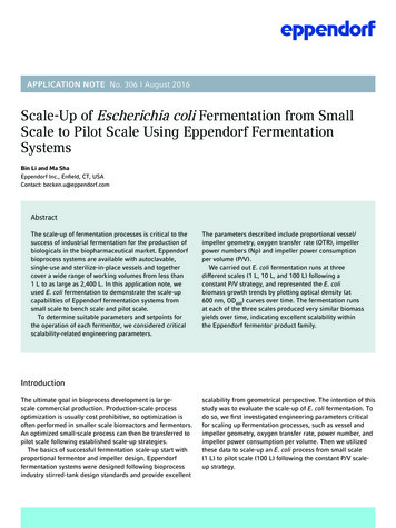
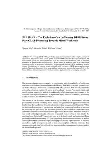
1 IntroductionThe main value of modern production is information, the amounts of which have become too large for a human to processeffectively. Technologies are changing faster than enterprises manage to integrate them; the level of automation isconstantly growing. However, it is not enough only to provide modern equipment for a factory, it is necessary to ensure theefficiency of its work [1]. This can be achieved by an adequate analysis of the incoming information and its subsequentprocessing. At the modern mechanical engineering site, the main work on the manufacturing of products is carried out onequipment with computer numerical control, therefore the optimization of the technological process often comes down tothe optimization of the program code for these machines. At the same time, the work on the analysis and processing ofinformation is not always fully automated due to the need to operatively adapt to the production environment, especially forsmall enterprises with small-scale production. In this area, it is necessary to quickly create production plans that can changedepending on the state of the process equipment and manufactured products, and the implementation of plans should beeffectively automated.Usually, the tasks of operational planning and automated production management are carried out by the manufacturingexecution systems (MES) [2]. They occupy an intermediate place in the hierarchy of enterprise management systems betweenthe level of information collection from equipment in workshops done by supervisory control and data acquisition (SCADA)systems [3] and the level of operations over a large amount of administrative, financial and accounting information done byenterprise resource planning (ERP) [2] systems. Nowadays on the Russian market there are three most popular largestsolutions: PHOBOS system, YSB.Enterprise.Mes system and PolyPlan system. PHOBOS is traditionally used in large andmedium-sized mechanical engineering enterprises. YSB.Enterprise.Mes originated from the woodworking industry andfocuses on the sector of medium and small enterprises. The PolyPlan system has a smaller set of MES functions, but ispositioned as an operational scheduling system for automated and flexible manufacturing in engineering [4].However, with all the attractiveness of such systems, due to the extensive set of functions provided and deep integrationinto the production processes in the enterprise at all stages, their practical implementation is a whole complex andexpensive project in itself that not all enterprises, especially small-scale and individual, can afford. In addition to this, inorder to work effectively with MES, high qualification of its operator is required.The developed solution given in this work is designed to solve a narrower class of problems - to simplify thetechnological preparation of production for small-scale mechanical engineering site, which can be based on the introductionof operative digital modeling and analysis of the technological process of the production site in order to optimize andgenerate programs for managing and monitoring the production process.2 IoT Automation Object ArchitectureA promising direction in the organization of automation of small-scale mechanical engineering production sites is theirfocus on network-centric control and management. The advantages of this approach are indisputable provided that complexnetwork-centric systems will have high reliability of operation and flexible control of technological processes. Figure 1shows an example of a network-centric architecture of a production site.Figure 1 – Three levels of network-centric control of a mechanical engineering working site76
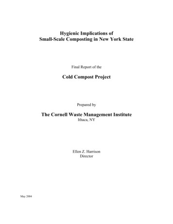
The levels depicted are as follows:1. The level of technological operations for CNC machines, robots and other objects that provide control actions and collectdata on the state of network objects.2. The level of technological processes (management of technological routes, which contain sequences of technologicaloperations).3. The level of multi-criteria hierarchical optimization and production planning.Modern implementations of distributed production networks [5] are usually based on special platforms that provideautomation of technological process logistics while control of the technological processing phases in appropriate modes iscarried out by instructions loaded via the network to CNC machines, robots and automated warehouses. Such solutions usepre-developed plans that exclude both operational adaptation necessary for changing nomenclature of small-scale orindividual orders and operational monitoring of states of working equipment and resources. This approach has proven itselfin the automation of mass production, while the IoT feature is the use of intelligent data center components that providepredictive and adaptive behavior of the workshop's technological processes based on the analysis of ''data lakes'' comingfrom production equipment.In the following, we describe the features of the Industrial Internet of Things platform for small-scale production.3 Formalization: From Drawing to Technological RouteFormalization of a detail uses modular technology, which implies an effective adaptation of the technological process to theproduct. The choice of surface and compound modules (SMs and CMs) of a detail as objects of classification allowsresolving the contradiction between continuous change of products and the desire for consistency in technologicalequipment. Since the detail is represented by a set of SMs and CMs, the technological processes of details manufacturingare built by assembling them from the modules of technological processes. In this case, the task of the technologist is toprovide each SM and CM with standard modules of technological equipment [6].The process of the formalization is carried out by the technologist on the basis of its drawing. He should highlight themodules to be processed in the drawing and provide the description of each with a variety of design and technologicalparameters, such as geometry, dimensional accuracy, surface hardness, processing method, necessary equipment, cuttingtools, cutting modes etc.For these purposes, the automated workplace of the technologist (AWT) is used (Fig.2).Figure 2 – Using AWT to select a cutting tool and its parametersThe technologist obtains the necessary parameters from the drawing, reference catalogues or other documentation. For anumber of parameters, ranges of possible values are specified.77
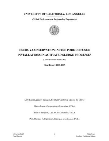
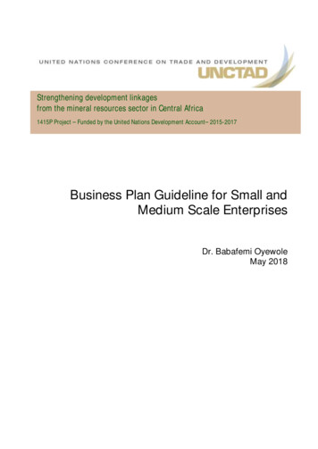
In addition to the surface modules, the modules for the technological process of manufactured detail, the modules forequipment and gear, the modules for instrumental adjustment and the modules for measuring instruments are described in asimilar way.Using modular formalization in AWT, the construction of technological blocks, modules to be processed in which usethe same tool for the processing, and technological groups, which divide processing blocks into phases, is automated. As aresult, technological routes (TRs) for manufacturing of a detail are formed from technological groups.All this information is recorded in a specialized database. Info about each technological route contains a list of surfacemodules with specified values of parameters. Information of each surface module contains a detailed description of themanufacturing operations necessary for its processing with symbolic parameters. By creating queries to the database, aroute with symbolic parameters, on the basis of which a specific detailed route will be created, is automatically formed.In the approach presented here we use the MSC language [7] for the encoding of the technological route. MSC is astandardized language for describing behaviors using message exchange diagrams between parallel-functioning objects(CNC, robots). The diagram example is shown in the Figure 3.Figure 3 – Example MSC diagram of a technological routeThe following messages are used in the diagram:1. Messages about the preparation of the next detail for processing and verification of its suitability to the requirements ofthe route.2. Messages checking the requirements for the necessary machinery and the availability of the machine.3. Requests about processing tools and their working modes.4. Requests about mounting fixtures.5. Messages requesting a set of cutting tools from the storage to the CNC.6. Messages about their retrieval on a pallet from the storage.4 Technological Route OptimizationTechnological route with symbolic parameters can be converted to a specific one by replacing the character variables withtheir values. In a case when the range for a value is specified, it is necessary to check its boundaries for the out-of-rangeerror, which is implemented using a symbolic verifier [8]. In the process of proving the correctness of a route, it is possibleto check various constraints on the sequence of surface modules within the route formulated by means of the first orderlogic. The contradictions found in the process of proof can be corrected by imposing additional restrictions on the statedsequences in the route or on the ranges of the parameter values.For the correct technological route with the help of the formulas stored in the database, the technologist can estimate thetime and cost of its processing. The fragment of the set of such formulas is shown in the Table 1.78
Table 1 – Formulas for turning time calculationsThe relative estimate of the route (Fig.4) can be obtained as the sum of the estimates of each operation on each individualsurface module that make up the route, which is sufficient for ranking alternative solutions on the choice of parameters ofthe route. To obtain absolute values, it suffices to use the multiplicative and additive correction factors obtained on the basisof statistical estimates of the technological processes of a particular production.Figure 4 – Illustration of a technological route consisting of 4 operations performed on 4 machinesThe correct route can be optimized. By changing the parameters of the route within the allowable ranges and recalculating the indicators of processing time and cost, the technologist can get a solution that meets the limitations of themanagement on a particular job or get the Pareto-optimal solution [9]. However, it should be noted that the mentionedoptimization is valid provided that the production by the route is carried out without taking into account the current stateand restrictions on the resources of the production site. Obtaining more realistic estimates is possible with the help ofsimulation modeling of the distribution of resources for the routes simultaneously performed at the production site.5 Digital Modeling of Technological Processes at the Production SiteThe digital model of the production site simulates the implementation of the production of different batches of details bydifferent specified technological routes. The site model is built on the basis of information on the resources of theproduction site (CNC machines, transport robots, warehouses, staff etc.) which include amounts of time for their usages.The size of the batch of details is also associated with the route.The model uses the method of dynamic priorities to simulate the workload of resources of the production site anddetermine the duration of the realization of the technological process for orders.The result of simulation modeling is a schedule for the implementation of the technological process (Fig.5), whichprovides an estimate of the time to manufacture a batch of details in accordance with a specific route along with an estimateof the lead time for all routes (Fig.6). A set of estimates of the time of execution of the route can be analyzed for thefulfillment of certain criteria and restrictions characterizing the conditions of the order.79
Figure 5 – Example of the production schedule chartFigure 6 – Time and cost estimations example of two technological routesIn this regard, the following tasks can be solved:1. Estimation of the minimal amount of additional resources that need to be allocated so that the total time for theimplementation of the route is not more than the specified value T0.2. Redistribution of processing tools between individual operations in order to minimize the total implementation time ofthe route (optimal transfer of resources from non-critical operations to critical ones).3. The use of time reserves T0 - T arising when the calculated time T of the implementation of the route is less than thespecified value T0 in order to further improve the process.In the process of implementing a specific work schedule (in a certain sense, optimal), various unforeseen failures arepossible: machine breakage, shortage of components, unforeseen delays in performing individual operations, etc. Therefore,the management system should continuously monitor the entire process and should have a mode for operative changing ofthe schedule for the implementation of the remaining work in the new environment in order to optimize it. Thus, it turns out80
that it is necessary to correct the process of implementing the set of necessary operations in real time taking into account theset requirements for optimization and the formulated criteria of optimality.In addition, when forming the structure of the management system, it is necessary to take into account the possibility ofmulti-criteria formulation of optimization problems, when several particular indicators of the quality of the production siteare set [10]. In this case, the task of ensuring the work of the production site in some Pareto-optimal mode can be set.Usually it is advisable here to use some physically justified form of the convolution of the vector optimality criterion andproceed to optimization by the corresponding generalized criterion.When solving problems of managing the work of a production site with a hierarchical structure, it is necessary to takeinto account the organization of interactions of processes at different hierarchical levels, both among themselves and withthe main control center. For this reason, it is advisable to refer to the principles of network-centric management andmethods of coordination in hierarchical systems. It is also advisable to use the methods of hierarchical construction ofPareto sets at various technological levels.6 Analysis of Simulation ResultsThe analysis of the results of modeling a set of technological routes consists in solving a multi-criteria task of selectingimplementation options for a technological process of the IoT system. It is assumed that the direct solution of the originalmulti-dimensional problem with a set of difficultly computable criteria is either impossible or impractical because of thelimitations determined by the requirement of execution time and consumed resources balance. The main difficulties areconnected with the high dimension of the vector of tunable (selectable) parameters of the IoT system and with a largenumber of partial optimality criteria. The proposed approach is based on the application of well-known system analysisprocedures to the specific subject area under consideration [9].It is necessary to develop a common, uniting all the technological processes, target criterion of the IoT system and analgorithm built on its basis - a management plan for the entire system, which distinguishes the network-centric controlsystem.7 Solution of the Problem of Multi-criteria ManagementThe major task to be solved has the form:f 01 ( x0 ) max,., f 0n0 ( x0 ) max,x0 X 0 R N 0 , x0 x(0) ( x1 (0),., xN 0 (0)),f 0 ( f , f ,., f ) is a set of objective criteria, which define requirements to the output parameters of the systembeing optimized, and X 0 is a set of variants of the considered system which are realizable physically and algorithmically.where1020n00A solution of the optimization task (selection of optimal variants) is understood as a setП f 0 ( X 0 ) П0 ( X 0 ) X 0of efficient (Pareto-optimal) solutions from X 0 .Applying the described constructive approach assumes solving the aggregation task, which requires taking into accountthe following specifics:1. General multi-level models of optimization processes allow reducing the initial complex task to a series of efficientlydecidable tasks using sequential aggregating (abstracting).2. The aggregation process starts at the zero, most detailed (low) level of system description where a direct solution of thetask is inefficient because of its complexity and high dimension.3. The number of aggregation levels is selected in such a way, that the final dimension of the vector of adjustableparameters was acceptable for applying standard procedures of optimization [11, 12].4. One can obtain more and more algorithmically simple objective functions (which are introduced informally at each levelderived by experts from the consistency conditions) with aggregation.81
7.1 Levels of the process of multi-criteria optimizationA model of levels of multi-criteria optimization is given in Fig.7:Figure 7 – Levels of the process of multi-criteria optimizationIn the considered model the initial low level corresponds to the most detailed description of the system with a bignumber of arguments and another big number of particular criteria, usually of high computational complexity. Asmentioned above, it is hard to solve the problem of constructing the set П f 0 ( X 0 ) П0 ( X 0 ) X 0 directly.According to the algorithm described below, a successive enlargement of the problem description is performed throughtransition to the next (higher) level which contains less variables and particular criteria. As a result, an observable set ofparticular criteria depending on a relatively small number of arguments is obtained at the highest (strategic) level.Constructing a Pareto set at this level becomes algorithmically feasible. Thus, moving upward is accompanied at each levelby introduction of aggregated variables and new sets of particular criteria, consistent with the criteria of the adjacent lowerlevel in the sense specified below. This process of successive aggregation and decomposition is described below.7.2 Aggregation levelsLet’s introduce aggregated parameters of the next 1st level:x(1) X 1 , X 1 R N1 , N1 N 0 ,x(1) 1 ( x(0)), X 1 1 ( X 0 ),where 1 are aggregation functions which define the structures of parameters of level 1 through parameters of level 0.Then experts should specify criteria of level 1:f1 ( x(1)) ( f11 ( x(1)),., f1n1 ( x(1))) .As N1 N 0 the set x(1) provides more integrated and enlarged description of the planning process than the set x(0) .Functions 1 and f1 should be consistent with f 0 , x (0), X 0 in such a way that plan 1, which is Pareto-better than plan 2w.r.t. criteria of level 1, was better than plan 2 w.r.t. criteria of level 0 as well.82
As a result of continuing the aggregation process, the following chain is obtained:x(0) X 0 R N 0 , f 0 ( x(0)) R n0 ;x(1) 1 ( x(0)) X 1 R N1 , N 1 N 0 , f1 ( x(1)) R n1 ; x(k 1) k 1 ( x(k )) X k 1 R N k 1 , N k 1 N k ,f k 1 ( x(k 1)) R nk 1 ; x(m) m ( x(m 1)) X m R N m , N m N m 1 ,f m ( x(m)) R nm .whereX k 1 k 1 ( X k ) {x(k 1) f k 1 ( x k ) / x(k ) X k },0 k m 1.Selecting the number m of aggregation steps (in real practice not greater than 4) is determined by the fact that thedimension of N m should not exceed 50 and criteria f m ( x (m)) should be algorithmically simple.After specifying all aggregation steps from bottom to top, the top-to-bottom very process of parameterized optimizationstarts (Fig.8). At the upmost (strategic) level m a respective Pareto set is constructed in accordance with the introducedcriteria of the upmost level. Then one goes down in the planning graph in accordance with the above equations until level 0is reached and the resulting Pareto set (a subset of it, to be exact) is constructed. The described process of optimization is aprocess of successive narrowing the set of considered (controlled) vectors on the basis of additional information in form ofintermediate vector criteria of optimality introduced at each hierarchical level. The introduced "level-ranked" criteria ofoptimality reflect the level of task details. As a result (and this is the main point), variants rejected "from generalconsiderations" at the previous hierarchical level are not analyzed at subsequent levels with more numerous and completesets of particular criteria.Figure 8 – Example of the process structure of objective optimization with net-centric control7.3 The master equation (algorithm) of the optimization processUpon execution of all aggregation steps, i.e., upon introducing x( k ), X k , f k ,0 k m, the multi-criteria component ofthe optimization task may be solved as follows.Let’s findП ( X m ) П f m ( X m ) Пm ( X m ) Пmand all solutions of the equation m ( x(m 1)) x(m), x(m) П m X m .These solutions define the set X m 1 m ( П m ). 183
Then let’s find the setsП m 1 ( X m 1 ) П m 1 , X m 2 m 1 1 ( П m 1 ) .The result of this process is П0 ( X 0 ).All this may be formalized in form of the master equation of multi-objective optimization:Пk П f k ( X k ) Пk ( k 11 ( П k 1 )),k m 1,.,0.П m П f m ( X m )Approbation of the described approach has demonstrated its applicability for deploying and managing technologicalprocesses within an industrial workshop with 8 adjustable criteria for its effective functioning.8 Inputs to the Process Control and Monitoring ModuleThe supervision sequences are generated from the extended MSC diagram, in which specially marked nodes containingdescriptions of alternative behaviors are expanded by analysis blocks, in the conditions of which the transition events to thealternative routes are encoded. The monitor module with a specific control and monitoring program is loaded on-line intothe process controller (Level 2 of the network-centric architecture, see Fig.1) and ensures that the work is performed inaccordance with the optimized schedule. Its task is to send and receive messages both to the machines and to thesmartphones of the staff.9 ConclusionThe final result of the work is the creation of a software system for the automation of the preparation and control of thetechnological processes of the mechanical engineering production site. Currently, a working prototype of the system hasbeen implemented, on which the following properties have been tested:1. Ability to quickly adapt to specific production conditions: equipment, resources and orders.2. Optimization of the characteristics of specific production processes in accordance with the selected set of criteria for itssuccess, carried out on-line.3. Efficiency assessment of the execution time and cost of the order, which is very important for the small-scale productionmanager with the flow of orders for small batches of different products that require different technological routes to beperformed.The platform provides a significant increase in the productivity of the technologist at the technological preparation phaseof production. Total preparation time decreases to approximately 1 day per order.Acknowledgements The work was financially supported by the Ministry of Education and Science of the RussianFederation in the framework of the Federal Targeted Program for Research and Development in Priority Areas ofAdvancement of the Russian Scientific and Technological Complex for 2014-2020 (14.584.21.0022, IDRFMEFI58417X0022).References[1] Solkin A (2012) Sposoby avtomatizatsii sozdaniya upravlyayushchikh programm dlya metallorezhushchegooborudovaniya s ChPU [Ways to automate the creation of control programs for metal-cutting equipment with CNC].In: Volzhsky University after V.N. Tatischev Gazette, (2 (19)):165--168. llorezhuschego-oborudovaniya-s-chpu Cited 11 Jul2019 (in Russian)[2] Frolov E, Zagidullin R (2007) MES-sistemy, kak oni est ili evolyutsiya sistem planirovaniya proizvodstva (chast II)[MES as they are or the evolution of the production planning systems (part II)]. tva.-chast-ii.html Cited 11 Jul 2019 (in Russian)[3] Davidyuk Y (2001) SCADA-sistemy na verkhnem urovne ASUTP [SCADA systems at the top level of advancedprocess control systems]. In: Intelligent Enterprise, 30(13). https://www.iemag.ru/platforms/detail.php?ID 16479Cited 11 Jul 2019 (in Russian)[4] Garaeva Y, Zagidullin R, Tsin S (2005) Rossiiskie MES-sistemy, ili Kak vernut proizvodstvu optimizm [RussianMES or how to return optimism to production]. In: SAPR i grafika [CAD and graphics] (11)https://sapr.ru/article/14614 Cited 11 Jul 2019 (in Russian)[5] Leondes, Cornelius T (2001). Computer-aided design, engineering, and manufacturing systems techniques andapplications. Boca Raton, FL CRC Press[6] Bazrov B (2001) Modulnaya tekhnologiya v mashinostroenii [Modular technology in mechanical engineering].Moscow "Mashinostroenie" ["Mechanical engineering"], 366 pp. (in Russian)[7] Recommendation ITUT Z. 120. Message Sequence Chart (MSC), 11/2000.84
[8] Baranov S, Kotlyarov V, Letichevsky A, Drobintsev P (2005) The Technology of Automation Verification andTesting in Industrial Projects. In: Proc. of St. Petersburg IEEE Chapter, International Conference, May 18-21, St.Petersburg, Russia, 81--86.[9] Chernorutsky I (2005) Decision Making Tools, ''BHV'', St. Petersburg, 418 pp. (in Russian)[10] Voinov N, Chernorutsky I, Drobintsev P, Kotlyarov V (2017) An approach to net-centric control automation oftechnological processes within industrial IoT systems. In: Advances in Manufacturing, 5 (4):388--393.[11] Chernorutsky I (2011) Optimization Tools. Computer Technologies, "BHV", St. Petersburg, 384 pp. (in Russian)[12] Chernorutsky I (2004) Optimization Tools in Control Theory, "Piter", St. Petersburg, 256 pp. (in Russian)85
focus on network-centric control and management. The advantages of this approach are indisputable provided that complex network-centric systems will have high reliability of operation and flexible control of technological processes. Figure 1 shows an example of a network-centric architecture of a production site.