Transcription
Basic Mechanics Applied to OrthodonticsDr. Jean-Marc RetrouveyDr. Katherine Kousaie1INTRODUCTIONOrthodontics is built upon the principles of physics that are studying moving bodies in space.The movements in orthodontics are more complicated, as these moving bodies are restrictedby the biological behavior of the dentoalveolar processes and are subject to more complexforce systems than simple mechanics can predict. Biomechanics is an important part oforthodontics. It is the study of static equilibrium and the effects of forces on biologicalsystems. This text will attempt to simplify the biomechanics in orthodontics and provide aframework for clinical applications.Smith, Richard J., and Charles J. Burstone. "Mechanics of tooth movement." American journal oforthodontics 85.4 (1984): 294-307.2BASIC MECHANICSThere are a few basic physics concepts that warrant review prior to delving into biomechanicsin orthodontics and its applications in clinical cases.In orthodontics, the three laws of Newton are used to explain the effects of forces on an object.2.1Newton’s Three LawsNewton’s Laws describe the motion of an object when subject to forces.Newton, Isaac. The Principia: mathematical principles of natural philosophy. Univ of California Press,1999.2.1.1 First LawIn the absence of friction, a body stays at rest or continues in uniform motion in a straight lineunless changed by forces acting on itNewton’s first law essentially describes the concept of inertia, or a body’s reaction (orresistance) to movement when acted upon by a force. (Fig 1).
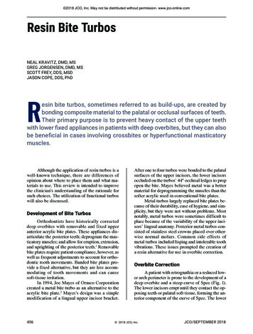
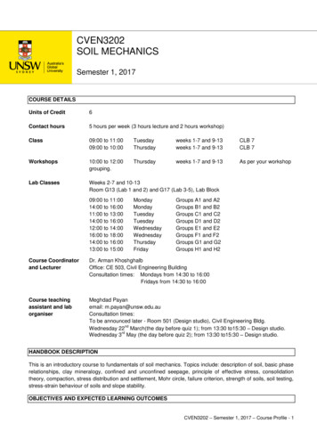
Figure 1: Newton's first law2.1.2 Second LawThe acceleration of a body is in the same direction as the force that produces it, and is relatedon the magnitude of the force, and inversely related to its mass.Fnet ma(Force mass x acceleration)In orthodontics, a tooth will “accelerate” in the direction of the force applied with a combination ofrotation and translation.2.1.3 Third LawNewton’s third law states that with every action or force, there is an equal reaction force (in theopposite direction). According to this law, whenever two objects interact, they exert action andreaction forces on each other. With any interaction there is a pair of forces. The forces in thispair (action and reaction) are vectors in that they have a size and a direction. The size of theforce on the first object is equal to the size of the force on the second object, and the directionof the force on the first object is in a direction opposite to the direction of the force on thesecond object.Consider the interaction between the wheels of an automobile and the road. As the wheelsturn, they exert a force on the road. In turn, the road exerts a force on the wheels that is equalin magnitude, and opposite in direction to the force the road receives from the wheels. In asense, the wheels push the road backwards, and the road pushes the wheels forward (equaland opposite), allowing the automobile to move forwards.In the mouth, we can see examples of action/reaction systems in the canine retraction setupshown below (fig 2). The spring pulls the canine back with a magnitude of force. Since theappliance uses the molars as anchorage, there is an equal magnitude and opposite direction
force pulling the molars forward. This forward force may be an undesirable side effect. Whentreatment planning, the undesirable side effects must be accounted for and minimized oreliminated.Figure 2: Action and reaction forces place the system in equilibrium33.1CONCEPT OF A FORCESimple force:3.1.1 Definition:A force is any action that results in the change in the motion of an object. Forces are measuredin ounces, grams or Newtons (approximately 100gr per 1 Newton on planet Earth as theacceleration due to gravity is considered constant and equal to 9.807m/s2). In orthodontics, theunit of forces used is usually the gram(2).Direction and magnitude of a forceAs a force is a vector, the direction of the force is represented by an arrow pointing in the samedirection as the movement of the tooth.The magnitude is represented by the length of the arrow (by convention).Figure 3: Simple force with direction and magnitude
3.1.2 Point of applicationThe point of application of the force is the location where the force is applied to the object andis by convention the origin of the arrow. The location of the point of application of the force isrelated to the center of mass as this precise location will determine the tendency of the objectto translate and/or rotate when submitted to this particular force.Figure 4: Point of application of forcesIn figure 4, the green and red forces are in different directions but have the same point ofapplication.3.1.3 Line of action with direction and magnitude.The line of action is the geometric representation of the way and direction the force is applied.The line of action is the line that extends the direction of the vector. The magnitude is thelength of the arrow by convention (Fig 5,6).
Figure 5: A simple force applied to the bracket of a central incisor. The line of action illustrates the direction of the vector of theforce.Figure 6: Line of action of forces;Two forces of equal amplitude acting in the same direction and placed on the same line ofaction will have the same effect on a rigid body. In figure 6, F1 and F2 will have the same effecton the blue body. It does not matter if one force is pushing and the other one is pulling. The neteffect will be identical.3.1.4 Law of Transmissibility of Force:The effect of a force on a body is the same when it is applied anywhere along its line of action(Fig 6). For example, if the line of action is the long axis of the tooth, it does not matterwhether the force is applied at the incisal edge, the bracket, or the cingulum: when the force isin the same direction and magnitude, the effect is the same.
Figure 7:Law of transmissibility of forces: F1 and F2 have the same effect3.1.5 Point of application of force:The law of transmissibility tells us that the same force (in the same direction) has the sameeffect if the point of application is anywhere along the same line of force.Scalars are used to describe forces; scalars have a magnitude, but no direction. Vectors havemagnitude and direction.Rigid Bodies: These do not change shape under the influence of forces (such as compressionand tensile forces). Teeth are rigid bodies; the same cannot be said for soft tissues!3.1.6 Center of MassThe center of mass represents the balance point of a system. In simple objects such as a tooth,the center of mass is a point where the position of distributed mass is equal to zero. If noforce(s) act on a body of mass, it would act as if all its mass were concentrated at a single point(the center of mass).
1. Center of mass: balancepoint of a systemCenter of massFFigure 8: Center of massIf a force goes through the center of mass, the object will move in the direction of the forcewithout rotation (translation).This goes for a box, a tooth or any other object for that matter, on the moon or in anenvironment where no forces are acting upon the object) (Fig 8). This is obviously not arealistic situation, but more of a theoretical concept!Figure 9:Centre of mass on the moon
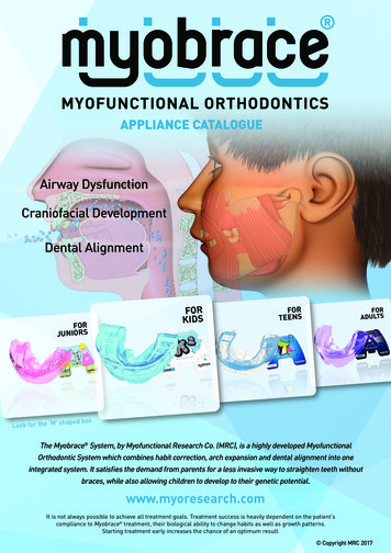
DirectionPoint ofapplicationCenter ofmassFigure 10: Line of action of a force placed at a distance from the center of massIf the line of action of a free body is placed away from the center of mass, a combination of arotation and a translation is to be expected (figure 9).4CENTER OF RESISTANCE (CR):The center of resistance (CR) is an important concept in orthodontics as the teeth are not freebodies, the roots being secured to the alveolar bone by the periodontal ligament. The center ofmass and the center of resistance are not located in the same position. CR is located moreapically than the center of mass. It is a mathematical point at which all resistance todisplacement are concentrated. Calculations of force systems in relation to their ability totranslate or rotate are performed in relation to the center of resistance.
Figure 11: Localization of the center of resistance according to several views: A. Radicular, B: Occlusal. C: Labio-lingual, D.:Mesio-Distal.The center of resistance varies with each tooth. Under normal periodontal condition, the CR ofa single root tooth is located between the middle and cervical third part of the root. On amultiple root tooth, the center of resistance is located one millimeter apical from the furcate.CR takes into account all the forces acting on a body. For a tooth, it includes forces from theperiodontal ligament (PDL), blood vessels, bone, and connective tissue (Fig 11). The centre ofresistance may be considered for a single tooth or for a group of teeth (when anchoredtogether and therefore acting together as one larger mass).Importance of the center of resistance: When forces are applied on teeth, it is imperative toassess their three-dimensional effects and the resulting movements that will occur once thetooth is subjected to this force system.
4.1Variability of the center of resistance in relation to periodontal supportAlveolar bone supportThe center of resistancewill move apically ifalveolar bone is lostFigure 12: The center of resistance moves apically with horizontal bone lossIf a patient presents with reduced periodontal support, the crest of the alveolar bone is moreapical and the center of resistance of the tooth has moved apically. The distance from thebracket to CR has increased by almost two-fold (figure 12). If the same force is applied at thebracket level on these two teeth, a different orthodontic movement will result. The tooth onthe right will tend to rotate more according to the increased distance from the line of action ofthe force to the center of resistance of the tooth.4.1.1 Center of resistance for a single tooth:The center of mass is always more occlusal than the center ofresistance due to the “resistance “of the periodontalligament and dentoalveolar bone. As this resistance isimpossible to quantify for each tooth and for each patient,the center of resistance is a theoretical concept but can beused as an average to create optimized force systems (Fig13).Figure 13: Center of resistance of amonoradicular tooth
In cases where the periodontal support is constant, the center of resistance of different teethwill be at different levels. The upper canines will have a higher center of resistance while thepremolars and lateral incisors will be positioned more occlusally (Fig 14).Figure 14: Different center of resistance positions (the periodontal support is even and normal).4.1.2 Center of resistance for a group of teeth.When teeth are tied by brackets and wires, a new center of resistance is establishedconsidering the fact that the group of teeth is now considered as a single object (Fig 15).Figure 15: Center of resistance for a group of teeth
Think about the centre of resistance as the point on the tooth where a single force applied atthis point results in pure translation (Fig 16). If the line of force is located at a distance such aswhen a force is applied to the crown of a tooth, some rotation will occur (Fig 17).Figure 16: Forces acting at the center of resistance result in translationFigure 17 : If the force is applied to the bracket, the line of force is always at a distance from the center of resistance
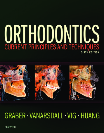
4.1.3 Combination of forces. Resultant of force or net forceIn orthodontics, combination of forces in the three planes of space are frequently used and it isuseful to calculate the net resultant force (Fnet or Fr). The parallelogram rule is used to calculatethe sum of the vectors (Fig 18).FrFigure 18: Parallelogram RuleIt is important to remember that the Force is the net force, which is the sum of the vectors ofall forces (F1 and F2). The parallelogram rule allows us to find the net force: Forces F1 and F2are vectors and have magnitude and direction. When F1 and F2 are at an angle to each other,the parallelogram is created by making F1 and F2 adjacent sides. The diagonal running throughthe parallelogram is the resultant force Fr (Fig 19).Calculations from the sum of 2 vectors (Please refer to this URL for detailed rallelogram-law-vector-addition)Figure 19: Calculation of the sum of the two vectors.In order to calculate the magnitude of the resultant force Fr, we use the fomula: Fr F1 F2We need to extend the line of action of F1 to create a square triangle OXR and add the α and βangles (Fig20).
Figure 20: Extension of the parallelogram.Calculation of the amplitude of Fr:Fr2 OX2 RX2 orFr2 (OFA FAX) 2 RX2Once fully expanded, we getCos β FAX/F2 or FAX F2Cosβ and sin β RX/F2 or RX F2sinβAfter substitution of values: Fr 𝐹12 2𝐹1𝐹2𝑐𝑜𝑠𝛽 𝐹22Figure 21: Resultant (net) force when forces at 90 degreesIn the case where we place the forces at 90 degrees, the equation is simplified and becomesFr 𝑋12 𝐹𝑌22 (Fig 21)
5CENTER OF ROTATION:The Centre of Rotation is the point around which the object rotates. This varies with the location of thecenter of resistance and the force applied to the object. Pure rotation occurs when the center ofrotation is at the center of resistance. Pure translation occurs when the center of rotation is at aninfinite distance away from the center of resistance.To locate the center of rotation about which a rotational tooth movement occurred as demonstrated inFig 22, choose any two points on the tooth (or object) and draw a line between the before and afterpositions of each point. The point of intersection between the perpendicular lines is the center ofrotation.Figure 22 Method to locate the center of rotationIt is evident that the center of resistance will vary from tooth to tooth according to root length andanatomy (incisors vs molars, premolars vs canines. Its position also varies with alveolar bone height, sothat it would be different in a child versus an adult with periodontal disease (center of resistance movesmore apical in adults who present with bone loss) (Fig 23)
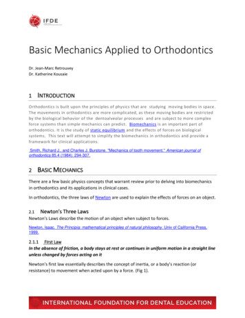
Figure 23: Bone loss results in migration of CR apically.5.1.1 Free Body DiagramsFree body diagrams help to predict the effect of different forces acting on a body at the sametime (Fr or Fnet) or to decompose a force into 2 perpendicular vectors.A clinical example of the use of a free body diagram is used to illustrate the effect of anintrusion arch combined with elastics (Fig 24).F1Figure 24: Simple force applied to the crown of an incisor.
A force F1 is applied which will generate intrusive and retrusive component forces. If we knowthe magnitude of the applied force and its angulation, we can find the magnitude of theintrusive and retrusive forces using simple trigonometry (Fig 25).F1FYFXFigure 25: Resultant force systemIf we know that F1 50g, we can calculate FY (Intrusive force) and FX (Retrusive force) using isthe right triangle ruleIf we assume that the angle of F1 is 45 degree to the X axis, thenFY F1 sin45 or 50x sin 45 35.3 grFX F1 cos 45 or 50x cos 45 35.3 grThus, a 50g force in the direction of F1 is the same as a 35.3g force in the direction of Y and a35.3g force in the direction of X.
5.2Conclusions of Part 1:In this introduction to biomechanics, we have defined the general applications of the three lawsof physics of Newton and explained the main definitions of the basic terms used inbiomechanics. Simple force systems have been defined and their primary effects on an objectintroduced.Calculations of the resultant force in two planes of space have been demonstrated.Recommended ReadingAntoszewska, J. and N. Küçükkeles (2011). Biomechanics of Tooth-Movement: Current Look atOrthodontic Fundamental, INTECH Open Access Publisher.Burstone, C. J. (1962). "Rationale of the segmented arch." American Journal of Orthodontics andDentofacial Orthopedics 48(11): 805-822.Burstone, C. J. (2011). "Application of bioengineering to clinical orthodontics." Orthodontics-E-Book:Current Principles and Techniques: 345.Burstone, C. J. and H. A. Koenig (1974). "Force systems from an ideal arch." American journal oforthodontics 65(3): 270-289.Burstone, C. J. and R. J. Pryputniewicz (1980). "Holographic determination of centers of rotation producedby orthodontic forces." American journal of orthodontics 77(4): 396-409.Choy, K., et al. (2002). "Controlled space closure with a statically determinate retraction system." TheAngle orthodontist 72(3): 191-198.Fiorelli, G., et al. (2001). "Differentiated orthodontic mechanics for dental midline correction." Journal ofclinical orthodontics: JCO 35(4): 239.Koenig, H. A. and C. J. Burstone (1989). "Force systems from an ideal arch—large deflectionconsiderations." The Angle orthodontist 59(1): 11-16.Lindauer, S. J. (2001). The basics of orthodontic mechanics. Seminars in Orthodontics, Elsevier.Meling, T. R., et al. (1997). "On mechanical properties of square and rectangular stainless steel wirestested in torsion." American Journal of Orthodontics and Dentofacial Orthopedics 111(3): 310-320.
Nyashin, Y., et al. (2016). "Centre of resistance and centre of rotation of a tooth: experimentaldetermination, computer simulation and the effect of tissue nonlinearity." Comput Methods BiomechBiomed Engin 19(3): 229-239.Ouejiaraphant, T., et al. (2018). "Determination of the centre of resistance during en masse retractioncombined with corticotomy: finite element analysis." Journal of Orthodontics 45(1): 11-15.Ren, Y., et al. (2004). "Optimum force magnitude for orthodontic tooth movement: a mathematic model."American Journal of Orthodontics and Dentofacial Orthopedics 125(1): 71-77.Rinchuse, D. J., et al. (2007). "Orthodontic appliance design." American Journal of Orthodontics andDentofacial Orthopedics 131(1): 76-82.Sakima, M. T., et al. (2016). "Quantification of the force systems delivered by transpalatal arches activatedin the six Burstone geometries." The Angle orthodontist 87(4): 542-548.Shroff, B., et al. (1995). "Segmented approach to simultaneous intrusion and space closure: biomechanicsof the three-piece base arch appliance." American Journal of Orthodontics and Dentofacial Orthopedics107(2): 136-143.Simon, M., et al. (2014). "Forces and moments generated by removable thermoplastic aligners: incisortorque, premolar derotation, and molar distalization." American Journal of Orthodontics and DentofacialOrthopedics 145(6): 728-736.Smith, R. J. and C. J. Burstone (1984). "Mechanics of tooth movement." American journal of orthodontics85(4): 294-307.Tepedino, M., et al. (2018). "Movement of anterior teeth using clear aligners: a three-dimensional,retrospective evaluation." Progress in Orthodontics 19(1): 9.Yee, J. A., et al. (2009). "Rate of tooth movement under heavy and light continuous orthodontic forces."American Journal of Orthodontics and Dentofacial Orthopedics 136(2): 150. e151-150. e159.
orthodontics. It is the study of static equilibrium and the effects of forces on biological systems. This text will attempt to simplify the biomechanics in orthodontics and provide a framework for clinical applications. Smith, Richard J., and Charles J. Burstone. "Mechanics of tooth movement." American journal of orthodontics 85.4 (1984): 294-307.