Transcription
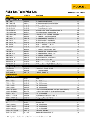
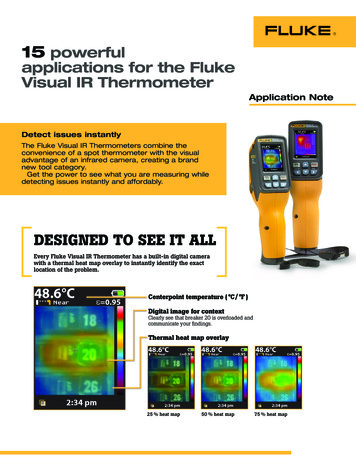
15 powerfulapplications for the FlukeVisual IR ThermometerApplication NoteDetect issues instantlyThe Fluke Visual IR Thermometers combine theconvenience of a spot thermometer with the visualadvantage of an infrared camera, creating a brandnew tool category.Get the power to see what you are measuring whiledetecting issues instantly and affordably.DESIGNED TO SEE IT ALLEvery Fluke Visual IR Thermometer has a built-in digital camerawith a thermal heat map overlay to instantly identify the exactlocation of the problem.Centerpoint temperature ( C/ F )Digital image for contextClearly see that breaker 20 is overloaded andcommunicate your findings.Thermal heat map overlay25 % heat map50 % heat map75 % heat map
1. Overloaded circuit breakerScan large electrical panels inseconds to find potential faultsthat generate heat, such asloose connections, imbalance oroverloading.Notice how the visual IRthermometer not only shows anapparent hot spot on a breaker,but the digital image also showsthe exact location where thepotential problem lies.Heat map overlayFull digital2. Overheated motor outputThis image reflects a motor that may beoverheated based on the center pointmeasurement of 54.8 C.The combination of the thermal heatmap and field of view in tight spacesis powerful orientation when troubleshooting and communicating neededrepairs to others.Heat map overlayFull digital3. Thermal inspection of bearingThe visual IR thermometer can be usedto scan bearings to compare temperature readings with past inspections orwith other bearings operating undersimilar conditions. Establishingtemperature benchmarks with theFluke Visual IR Thermometer canbecome an important part of yourpreventive maintenance regimen.Heat map overlay2 Fluke CorporationImages portrayed are actual images fromFluke Visual IR Thermometers. ProperPPE Gear should be worn at all times.Full digital15 powerful applications for the Fluke Visual IR Thermometer
4. Potentially faulty cold air damperUse your visual IR thermometer to see howwell the VAV box is working by scanningvents. The warm area in this otherwisecold vent could indicate a faulty cold airdamper.Heat map overlayFull digital5. Uneven distribution in AC condenserIn this typical AC condenser, the unevendistribution of heat in the center row mayindicate a potential issue.Heat map overlayFull digital6. Inspection of compressor thermal expansion valveThe thermal heat map allows youto quickly scan the compressor anddetermine that the TXV (thermalexpansion valve) to the left appearsto be cold, indicating that it is closed.Images portrayed are actual images fromFluke Visual IR Thermometers. ProperPPE Gear should be worn at all times.Heat map overlay3 Fluke CorporationFull digital15 powerful applications for the Fluke Visual IR Thermometer
7. Non-operational AC compressorThe compressors in these images arerunning on a 4-stage system. Thesecond stage compressor appeared cold,while the other three compressors in thesystem all appeared hot. This compressorwill need to be further investigated.Stage 2 CompressorOne of the Operational Stages8. Thermal inspection of combination starterUse a Fluke Visual IR Thermometer tolook for connection or overload conditionsin combination starters. Alarm featureson the VT04, as well as the universaltripod mount, can help you troubleshootintermittent issues unattended.Heat map overlayFull digital9. Main breaker for mission critical equipmentThis main service breaker controls themain breaker panel for the company’s ITdepartment. A fault could cause an outageof mission critical data center equipment.The thermal inspection of this importantbreaker indicates that there is even heatdistribution which signifies that theredoes not appear to be anything wrong.Heat map overlay4 Fluke CorporationFull digital15 powerful applications for the Fluke Visual IR ThermometerImages portrayed are actual images fromFluke Visual IR Thermometers. ProperPPE Gear should be worn at all times.
10. Unbalanced load in three phase supplyQuickly identify apparent unbalancedloadings. In this image, the fuses areconnected to a water heater, and themost likely scenario is that the two fuseson the left are being used more than thefuse on the right. This could indicate aproblem with the heating element in thewater heater. If this were single phasing,it could indicate that the fuse on the rightmay be blown. The next step is to checkcontinuity of the fuse and current loadson the 3 phases.Heat map overlayFull digital11. Power factor correction capacitorsPower factor correction capacitorswill usually run warm when they areoperating correctly. A failed capacitorwill show up as cool in comparison withthe operating capacitors.Heat map overlayFull digital12. Preventive inspections of pulleys and beltsIf a pulley appears warmer than expected,you’ll want to inspect the belt to ensurethere is no slippage, misalignment, ordamage to the belt. A quick scan withthe thermal heat map on the visual IRthermometer can help you quicklydetect a temperature change that maybe cause for further investigation.Images portrayed are actual images fromFluke Visual IR Thermometers. ProperPPE Gear should be worn at all times.Heat map overlay5 Fluke CorporationFull digital15 powerful applications for the Fluke Visual IR Thermometer
13. Environmental monitoring of fan for high-powered equipmentIf a fan starts to seize up, workers in thearea may not notice until there is a burning smell. However, a quick scan with theblended thermal heat map reveals the hotand cold areas to help determine if thefans are functioning as expected.Heat map overlayFull digital14. Troubleshoot issues with radiant flooringThis radiant flooring was scanned tocheck for the expected heat pattern.For best results, leave the radiant systemoff for 24 hours to cool down. Poweron the system again and scan theflooring to check for the expectedthermal heat pattern.To find potential issues in electricalbased systems, look for cold spotsthat are anomalies in the normal heatpattern. For hydronic systems, look forcold spots or a spreading hot spot thatcould indicate the pipes are leaking.Heat map overlayFull digital15. Heat loss from windows and doorsThe Fluke Visual IR Thermometer can helpyou find a broken or damaged windowseal that is allowing a coldor warm draft to occur around windows ordoors.Heat map overlay6 Fluke CorporationFull digital15 powerful applications for the Fluke Visual IR ThermometerImages portrayed are actual images fromFluke Visual IR Thermometers. ProperPPE Gear should be worn at all times.
Set yourself up for successFollow a few simple steps that will help youtroubleshoot issues in facilities applications: Wear proper PPE for your environment, according to your local, national, and companyprotocols. Always remain the proper distanceaway from potentially hazardous equipment. Have direct access to the target you are scanning. Disassembly may be required aroundyour target. When you’ve found a potential issue usingthe blended heat map, move closer to take acenter-point temperature measurement. Understand how surface material characteristics such as emissivity can influence yourreadings.Professional SmartView reporting software includedwith purchase.Automated monitoring alarms available on the VT04.Fluke Europe B.V.P.O. Box 11865602 BD EindhovenThe NetherlandsWeb: www.fluke.co.ukFor more information call:In Europe/M-East/Africa 31 (0) 40 2 675 200 orFax 31 (0) 40 2 675 222Fluke (UK) Ltd.52 Hurricane WayNorwich, NorfolkNR6 6JBUnited KingdomTel.: 44 (0) 20 7942 0700Fax: 44 (0) 20 7942 0701E-mail: industrial@uk.fluke.nlWeb: www.fluke.co.uk 2013 Fluke Corporation. All rights reserved.Data subject to alteration without notice.8/2013 Pub ID: 12110--engModification of this document is not permittedwithout written permission from Fluke Corporation.7 Fluke Corporation15 powerful applications for the Fluke Visual IR Thermometer
6. Inspection of compressor thermal expansion valve The thermal heat map allows you to quickly scan the compressor and determine that the TXV (thermal expansion valve) to the left appears to be cold, indicating that it is closed. 4. Potentially faulty cold air damper Use your visual IR thermometer to see how well the VAV box is working by scanning