Transcription
SLAC-PUB-13923Quantum Anomalous Hall Effect in Hg1 y Mny Te Quantum WellsChao-Xing Liu1,2 , Xiao-Liang Qi2 , Xi Dai3 , Zhong Fang3 and Shou-Cheng Zhang221Center for Advanced Study, Tsinghua University,Beijing, 100084, ChinaDepartment of Physics, McCullough Building, Stanford University, Stanford, CA 94305-4045 and3Institute of Physics, Chinese Academy of Sciences Beijing, 100080, ChinaThe quantum Hall effect is usually observed when the two-dimensional electron gas is subjectedto an external magnetic field, so that their quantum states form Landau levels. In this work wepredict that a new phenomenon, the quantum anomalous Hall effect, can be realized in Hg1 y Mny Tequantum wells, without the external magnetic field and the associated Landau levels. This effectarises purely from the spin polarization of the M n atoms, and the quantized Hall conductance ispredicted for a range of quantum well thickness and the concentration of the M n atoms. This effectenables dissipationless charge current in spintronics devices.PACS numbers: 75.50.Pp 73.43.-f, 72.25.Dc, 85.75.-dWhen the two-dimensional electron gas (2DEG) is subjected to a high magnetic field, electronic states formLandau levels. In the regime where the temperature islow compared to the spacing between the Landau levels, quantized Hall conductance can be observed. In thequantum Hall (QH) regime, the electric current flows unidirectionally along the edge of the sample. Since backscattering is absent, the edge current flows without anydissipation. The breaking of the time reversal symmetryis a necessary condition for the Hall effect. However, anexternal magnetic field is not required. Soon after theobservation of the Hall effect, Edwin Hall also observedthe anomalous Hall effect[1], where an additional Hallresistance arises from the spin-orbit interaction betweenthe electric current and the magnetic moments. In theextreme case, an anomalous Hall effect can occur withoutthe external magnetic field as long as the system breakstime-reversal symmetry spontaneously. Given the experimental observation of the QH effect, it is natural to askwhether the anomalous Hall effect can also be quantizedwithout the external magnetic field and the associatedLandau levels. Such a question is not only of great academic interests, but also has important practical implications. Realizing dissipationless charge current throughthe quantum anomalous Hall (QAH) effect without anexternal magnetic field could enable a new generation ofquantum electronic devices.Some years ago, Haldane[2] constructed a theoreticaltoy model to show that the QH effect is in principle possible without Landau levels. The model describes thehopping of spinless fermions on a honeycomb lattice,where the next-nearest neighbor hopping has complexamplitudes. Even though the complex hopping amplitude breaks the time reversal symmetry, it does not breakthe lattice translation symmetry since the net magneticflux vanishes inside an unit cell. Haldane’s model was extended to include localization physics in Ref.[3]. Unfortunately, this model is mostly academic, and can not be realized in the recently discovered graphene system. Later,the work on intrinsic anomalous Hall effect of ferromagnetic semiconductor in the metallic regime[4, 5, 6] showsthe relation between the Berry’s phase and Hall conduc-tance. Qi, Wu and Zhang[7] constructed a tight-bindingmodel of electrons spin-orbit coupled to polarized magnetic moments, and showed that the Hall conductancecan be quantized in appropriate parameter regimes. Thismodel breaks the time reversal symmetry due to magnetic moments rather than Landau levels, and providesanother example of the QAH effect. More recently, aclosely related topological phenomenon known as quantum spin Hall (QSH) effect has been theoretically predicted and experimentally observed in HgTe quantumwells[8, 9]. In this work, we show that when the HgTequantum wells are doped with the magnetic Mn atoms,the QAH effect can be realized within an experimentallyaccessible parameter regime. We propose an experimentto demonstrate that the quantized Hall conductance indeed arises from the magnetic moments rather than Landau levels.As a starting point, we first briefly review the physicsof QSH effect in HgTe quantum wells. HgTe has an inverted band structure, where the p-type Γ8 band hashigher energy compared to the s-type Γ6 band at theΓ point. For HgTe/CdTe quantum wells, there exists atopological quantum phase transition across some criticalwell thickness dc where the band structure changes fromthe normal to the inverted character. The novel QSHeffect occurs in the inverted regime d dc [8]. In orderto describe the physics near dc , an effective four-bandmodel is introduced as h (k)0H0 (k) ,(1)0h (k)whereh (k) ǫk M(k)Ak Ak ǫk M(k) .(2)and h (k) h ( k) as is required by time-reversal symmetry. ǫk and M(k) can be in general expanded asǫk C0 C2 k 2 ,M(k) M0 M2 k 2 .(3)This effective model is expressed in the subspace containing the states E1, i and H1, i, where E1, i is a superposition of Γ6 , 21 i and Γ8 , 21 i states, while H1, iSIMES, SLAC National Accelerator Center, 2575 Sand Hill Road, Menlo Park, CA 94309Work supported in part by US Department of Energy contract DE-AC02-76SF00515.
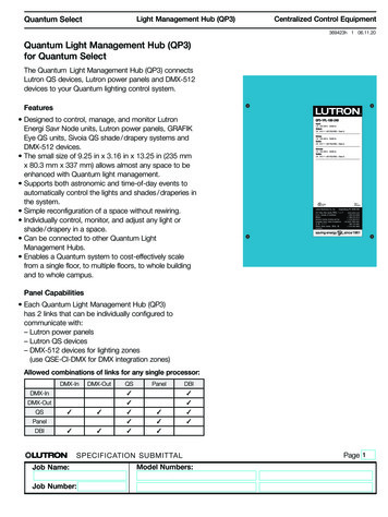
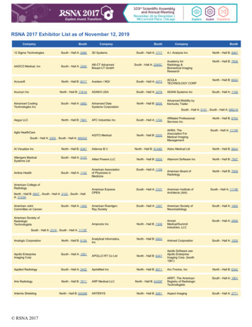
2is formed by Γ8 , 32 i states. Here denote the two spinstates which are degenerate due to the Kramers theorem when the time reversal symmetry is preserved. Thediagonal block h (k) describes a Dirac model in 2 1 dimensions, which at half filling carries a Hall conductanceof e2 /h, respectively[2, 7, 8]. Thus the net Hall conductance of the inverted quantum well system vanishes,while the spin Hall conductance, defined as the difference between the two blocks, is still non-zero. Thereforethe QSH effect can be viewed as two copies of the QAHeffects, with the opposite quanta of Hall conductances.When the time reversal symmetry is broken, the twospin blocks are no longer related, and their charge Hallconductances no longer cancel exactly. The key idea ofthis work is to identify the parameter space where onespin block is in the normal regime, while the other spinblock is in the inverted regime. The normal regime givesa topologically trivial insulator with vanishing Hall conductance, while the inverted regimes gives a topologically non-trivial insulator with one quantum unit of theHall conductance; therefore, the whole system becomesa QAH state. Now we return to the four band effective Hamiltonian (1) and address what kind of term caninduce the QAH effect. To describe the spin splitting induced by the magnetization, a phenomenological term isintroduced as GE 00000 0 GHHs .(4)00 GE0 000 GHwhere the spin splitting is 2GE for the E1, i band and2GH for the H1, i band. Then the energy gap is givenby Eg 2M0 GE GH for the up spin block whileEg 2M0 GE GH for the down spin block. In order toobtain the QAH effect, we require that (1) the state withone kind of spin is in the inverted regime while the othergoes into the normal regime, namely Eg Eg 0; (2) theentire system is still in the insulating phase with a fullbulk gap, which requires that the states E1, i ( E1, i)and H1, i ( H1, i) do not cross each other, leading tothe condition (2M0 GE GH )(2M0 GE GH ) 0.Combining the two conditions discussed above, we arriveat the condition GE GH 0, which requires that the spinsplittings for E1, i and H1, i must have the opposite sign. This condition is illustrated in Fig. 1(a). Wecan also understand the physics from the edge state picture (Fig 1 (b)). On the boundary of a QSH insulatorthere are counter-propagating edge states carrying opposite spin. When the spin splitting term increases, thespin down edge states penetrate much deeper into thebulk due to the decreasing gap, and eventually disappear, leaving only the spin up state bound more stronglyto the edge. Thus the system has only spin up edge statesand transforms from the QSH state to the QAH state, asillustrated in Fig 1 (b).We have therefore identified a key condition GE GH 0, for the QAH effect. We may ask whether or not(a)(b)yx(c)FIG. 1: (Color online) Evolution of band structure and edgestates upon increasing the spin splitting. For (a) GE 0 andGH 0, the spin down states E1, i and H1, i in the sameblock of Hamiltonian (1) touch each other and then enters thenormal regime. But for (c) GE 0 and GH 0, gap closingoccurs between E1, i and H1, i bands, which belongs todifferent blocks of Hamiltonian, and thus will cross each otherwithout opening a gap. In (b), we show the behavior of theedge states during the level crossing in the case of (a).it is true in the realistic material. Fortunately, in theCdx Mny Hg1 x y Te /Mny Hg1 y Te quantum well, thesp-d exchange coupling indeed gives the opposite signsfor GE and GH , a fact which is well established in theliterature[10, 11]. From a standard perturbative treatment of the eight band Kane model[8, 12], we find fora spin polarization perpendicular to the quantum wellplane, the coefficients GE , GH in the four-band effectivemodel (4) can be expressed asGE (3AF1 BF4 ), GH 3B,(5)in which A, B are given by[11, 13]A 11N0 αyhSi, B N0 βyhSi,66(6)and F1 , F4 are the amplitudes of Γ6 , 12 i and Γ8 , 12 icomponents in the state E1 , i, respectively. Here N0 isthe number of unit cells per unit volume and hSi is thespin polarization of Mn out of quantum well plane. αand β describe the sp-d exchange coupling strength fors-band and p-band electron respectively, where the signsand magnitudes are crucial for the relative sign of GEand GH . For Hg1 y Mny Te, these parameters are determined to be N0 α 0.4eV and N0 β 0.6eV [11, 13],leading to the opposite signs for GE and GH . Combined with the previous analysis about the Hamiltonian (4), we conclude that QAH effect can occur in the
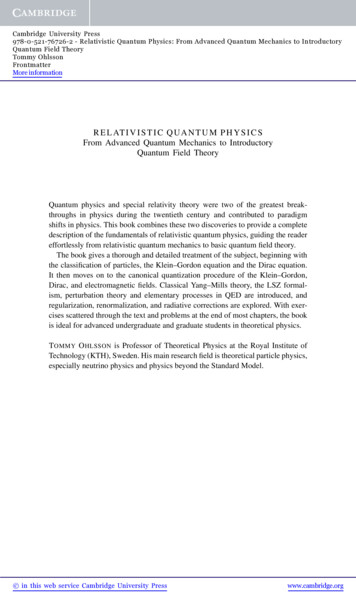
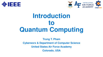
3FIG. 2: (a) The energy levels for E1, i and H1, i areplotted as a function of the quantum well thickness. Twocrossing points (A and B) are labelled in the figure. Theenergy gap (log(Egap ) used here) is plotted as a function of thewell thickness d versus the M n magnetic moment hSi in (b),versus the M n doping concentration y in (c). Dashed blue linein (b) or (c) refers to the line along which (a) is plotted. Thepoints ’A’ and ’B’ correspond to the two Dirac type crossingpoints. Two different phases, conventional insulator (CI) withσH 0 and QAH state with σH e2 /h, are separated bythe gap closing line in the figures.Cdx Mny Hg1 x y Te/Mny Hg1 y Te quantum well, as longas the Mn magnetization hSi is large enough and perpendicular to the quantum well plane.Though the analysis above already gives a clear explanation to the physical mechanism of QAH effect, to obtain more quantitative predictions we perform a more realistic calculation of the electronic structure based on theeight band Kane model[12, 13]. Our Hamiltonian takesinto account the exchange term and bulk inversion asymmetry (BIA) terms[12], in addition to the terms includedin the original Kane model. In Fig. 2 (a), the energyspectrum of the lowest subbands E1, i and H1, iat the Γ point is plotted as a function of quantum wellthickness d. At a critical thickness dc1 7.25nm, a levelcrossing ‘A’ occurs between the E1, i and the H1, ibands. This is a Dirac-type level crossing, which corresponds to a topological quatnum phase transition, acrosswhich the Hall conductance jumps by e2 /h. Since thesystem at d dc1 always remains gapped when theM n magnetization is adiabatically turned on, we knowσH 0 for d dc1 and σH e2 /h for d dc1 .The same analysis applies to the other critical thicknessdc2 9.4nm (‘B’ in Fig 2 (a)), where the level crossing occurs between E1, i and H1, i bands and theHall conductance returns to 0. Therefore, for parametershSi 2 and y 0.02, QAH effect appears in a quantumwell thickness range dc1 d dc2 . The same calculationcan be carried for different spin polarizations hSi or y todetermine the whole phase diagram with three tunableparameters: quantum well thickness d, spin polarizationhSi and M n fraction y. In Fig. 2 (b) and (c), the gapsizes in the d-hSi plane and the d-y plane are plotted, respectively. The line with bright color shows the phaseboundary with vanishing gap. At zero hSi or zero ylimit, the time-reversal invariance is recovered and thecritical line terminates at the transition point betweentrivial and QSH insulators[8]. An important feature ofthe phase diagram is that a minimal hSi (for fixed y)or minimal y (for fixed hSi) is required to obtain QAHphase. For example, for y 0.02 we need hSi 0.5 forthe QAH phase. This is a consequence of bulk inversionasymmetry (BIA).We now discuss the experimental observation of theQAH effect in the Hg1 y Mny Te system. The main difficulty lies in the fact that Hg1 y Mny Te is paramagneticrather than ferromagnetic. Thus the spin polarization isdetermined by the Curie-Weiss formula: 5gMn µB BhSi S0 B5/2(7)2kB (T T0 )where S0 5/2 and B5/2 is the Brillioun function[12, 13],and T0 0 stands for a weak antiferromagnetic couplingbetween M n spins. Hence, we need to apply a smallmagnetic field to polarize the Mn moments and generate the QAH effect. In fact, experiments carried outat the University of Würzburg has already shown quantized Hall conductance for magnetic fields as small as1T [14]. However, since even such a small magnetic fieldstill has an orbital effect, this experiment by itself cannot prove the existence of the QAH, which arises purelyfrom the magnetic moments of Mn. To solve this problem, we propose two different ways to polarize Mn spinswithout an orbital magnetic field. The first approach isto apply a low-frequency polarized infrared light to provide the angular momentum required for aligning the Mnmoments. Such a photo-induced Mn magnetization hasbeen observed experimentally both in Hg1 x Mnx Te andCd1 x Mnx Te[15, 16]. Though this proposal has the advantage of realizing this effect in a steady state, anotherapproach, the time-resolved Hall measurement, can provide a more dramatic demonstration of the QAH effect.Thus in the following we will focus on the time-resolvedHall measurement proposal. Firstly, a static magneticfield is applied, which acts on the itinerant electronsthrough three terms: the orbital effect Horb , the Zeeman term HZ and the exchange term Hex . In Hex , theMn spin polarization is determined by Eq. (7). Secondly,at time t0 the magnetic field is switched off within a timescale τB . As a result, the Mn spin polarization will decayto zero in a spin-relaxation time τs . However, if τB τs ,there is a time window t0 τB t t0 τs when theorbital and Zeeman effect of the magnetic field alreadydisappeared, but the Mn spin polarization remains similar to the value before magnetic field is removed. Consequently, within this time range there is no conventionalQH based on Landau levels, so that the pure QAH effect
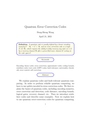
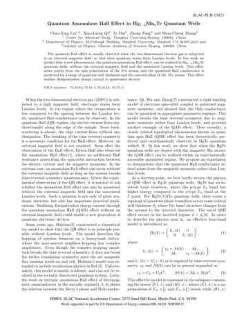
4(b)E (eV)E (eV)(a)B(T)B(T)(c)Region CRegion BRegion A11t0t1t0t1 t0 τstt0t1 t0 τstFIG. 3: Landau level spectra are plotted as a function ofmagnetic field (blue line) for two different thicknesses (a) d 8.5nm and (b) d 7.6nm, taking into account exchange term,Zeeman splitting and orbital effect. The corresponding redlines show the band edge of the sub-bands H1, i and E1, iwhen the magnetic field has been turned off but the Mn spinpolarization remains. Without an external magnetic field,the system is in a QSH insulator phase for (a), and trivialinsulator phase for (b). Figure (c) shows schematically thepredicted Hall conductances for the three different regions A,B and C defined by shadows in figure (a) and (b).can be observed, if the Mn spin polarization stays in thecorrect range.To illustrate this proposal more clearly, we comparethe band structure with and without Landau levels. InFig 4 (a) and (b), the energy spectra is plotted as a function of the magnetic field for different thicknesses. Theblue lines take into account the orbital magnetic fieldterm, the exchange and the Zeeman terms, corresponding to the spectra at time t τB , (setting t0 0). Incontrast, the red lines are the conduction and valenceband edges of the system at time τB t τs , afterthe orbital and Zeeman effects of the magnetic field areswitched off but the Mn spin polarization remains thesame. Since the energy spectrum is dispersive when theorbital effect of magnetic field is absent, the system isinsulating only when the fermi energy lies between thetwo middle red lines, i.e., between E1, i and H1, ifor Fig. 4 (a), or between E1, i and H1, i for Fig. 4(b). Depending on the initial values of fermi energy EFand magnetic field B, three different phenomena can beobserved in the proposed experiment. (i) When (EF , B)is in Region (A) of Fig. 4 (a), the system has Hall conductance σH e2 /h in the static magnetic field, and entersa trivial insulator phase after magnetic field is switchedoff. Consequently, the Hall conductance will drop to zeroonce the magnetic field is removed. (ii) When (EF , B)[1] C. L. Chien and C. R. e. Westgate, The Hall Effect andits Applications (Plenum, New York, 1980).is in Region (B) of Fig. 4 (a) and (b), the system hasHall conductance σH e2 /h for static field and entersa QAH phase with the same Hall conductance after themagnetic field is switched off. Thus the Hall conductancewill remain on the e2 /h plateau for a time τs aftermagnetic field is turned off. (iii) When (EF , B) is in Region (C) of Fig. 4 (b), the system has vanishing Hallconductance in static field, but enters a QAH phase withσH e2 /h after the magnetic field is switched off. Consequently, we will observe the dramatic appearance of a“pulse” of the Hall conductance in a time-scale τs eventhough the system is in the σH 0 Hall plateau undera static field! Observation of this phenomenon gives theconclusive demonstration of the QAH effect. Due to thetopological distinction between σH 0 and σH e2 /hstates, the transition between them is always sharp at lowtemperature, even though the Mn magnetization changescontinuously. Consequently, the time-dependence of σxxand σxy in this proposal should show the same criticalbehavior as the usual “plateau transition” in the QH effect.Finally, we estimate the experimental conditions required to realize this proposal. First of all, both of theswitch-off time τB and the time resolution δt[17] of theHall measurement should be shorter than Mn spin relaxation time τs , which is of the order 10 100µs[18, 19].Further, the magnetic field should be turned off slowlyenough for electrons to stay in the instantaneous groundstate during the switch-off operation (adiabatic condition), which requires τB h̄/Eg , where Eg is the energygap and h̄/Eg 10 12 s in the present system. Therefore, a magnetic field of several Tesla needs to be switchedoff in a time scale of 10 12 s τB 10 4 s, and thetime-resolution of transport measurement should satisfyδt 10 4 s.We have benefited greatly from the close interactionwith our experimental colleagues at the University ofWürzburg, in particular, H. Buhmann, M. König andL. Molenkamp; without their generous sharing of the experimental data and their insights on the experimentalfeasibility this work would not have been possible. Theauthors also would like to thank K. Chang, T. Hughes,R. B. Liu, S. Q. Shen, J. Wang, F. Ye and B. F. Zhu forhelpful discussions. This work is supported by the NSFunder grant numbers DMR-0342832 and the US Department of Energy, Office of Basic Energy Sciences undercontract DE-AC03-76SF00515. XD and ZF acknowledgesupport from the NSF and National Basic Research (973)Program of China (No.2007CB925000). CXL acknowledges the support of China Scholarship Council, NSFof China (Grant No.10774086, 10574076), and the Program of Basic Research Development of China (GrantNo. 2006CB921500).[2] F. D. M. Haldane, Phys. Rev. Lett. 61, 2015 (1988).
5[3] M. Onoda and N. Nagaosa, Phys. Rev. Lett. 90, 206601(2003).[4] T. Jungwirth, Q. Niu, and A. H. MacDonald, Phys. Rev.Lett. 88, 207208 (2002).[5] Z. Fang, N. Nagaosa, K. S. Takahashi, A. Asamitsu,R. Mathieu, T. Ogasawara, H. Yamada, M. Kawasaki,Y. Tokura, and K. Terakura, Science 302, 92 (2003).[6] F. D. M. Haldane, Phys. Rev. Lett. 93, 206602 (2004).[7] X.-L. Qi, Y.-S. Wu, and S.-C. Zhang, Phys. Rev. B 74,085308 (2006).[8] B. A. Bernevig, T. L. Hughes, and S.-C. Zhang, Science314, 1757 (2006).[9] M. Konig, S. Wiedmann, C. Brune, A. Roth, H. Buhmann, L. W. Molenkamp, X.-L. Qi, and S.-C. Zhang,Science 318, 766 (2007).[10] A. K. Bhattacharjee, G. Fishmano, and B. Coqblin,Physica B C 117-118B, 449 (1983).[11] J. K. Furdyna, J. Appl. Phys. 64, R29 (1988).[12] R. Winkler, Spin-Orbit Coupling Effects in TwoDimensional Electron and Hole Systems (Springer,Berlin, 2003).[13] E. G. Novik, A. Pfeuffer-Jeschke, T. Jungwirth, V. Latussek, C. R. Becker, G. Landwehr, H. Buhmann, andL. W. Molenkamp, Phys. Rev. B 72, 035321 (2005).[14] H. Buhmann, J. Liu, Y. S. Gui, V. Daumer, M. Koenig,C. R. Becker, and L. W. Molenkamp, Anomalous halleffect in magnetic quantum wells, Proc. 15th Int. Conf. onHigh Magnetic Fields in Semiconductor Physics, Oxford,5-9 August 2002.[15] H. Krenn, W. Zawadzki, and G. Bauer, Phys. Rev. Lett.55, 1510 (1985).[16] D. D. Awschalom, J. Warnock, and S. von Molnár, Phys.Rev. Lett. 58, 812 (1987).[17] W. Lu, Z. Ji, L. Pfeiffer, K. W. West, and A. J. Rimberg,Nature 423, 422 (2003).[18] A. V. Scherbakov, A. V. Akimov, D. R. Yakovlev, W. Ossau, G. Landwehr, T. Wojtowicz, G. Karczewski, andJ. Kossut, Phys. Rev. B 62, R10641 (2000).[19] A. M. Witowskia, T. Strutzb, C. Kutterb, and P. Wyder,Physica B 211, 372 (1995).
Work supported in part by US Department of Energy contract DE-AC02-76SF00515. Quantum Anomalous Hall Effect in Hg 1 yMn yTe Quantum Wells Chao-Xing Liu1, 2, Xiao-Liang Qi , Xi Dai3, Zhong Fang3 and Shou-Cheng Zhang2 1 Center for Advanced Study, Tsinghua University,Beijing, 100084, China 2 Department of Physics, McCullough Building, Stanford University, Stanford, CA 94305-4045 and