Transcription
International Conference on Computing in High Energy and Nuclear Physics 2012 (CHEP2012) IOP PublishingJournal of Physics: Conference Series 396 (2012) d error and alarm processing in the CMS dataacquisition systemG Bauer6, U Behrens1, M Bowen2, J Branson4, S Bukowiec2, S Cittolin4, J ACoarasa2, C Deldicque2, M Dobson2, A Dupont2, S Erhan3, A Flossdorf1, D Gigi2,F Glege2, R Gomez-Reino2, C Hartl2, J Hegeman2,a, A Holzner4, Y L Hwong2, LMasetti2, F Meijers2, E Meschi2, R K Mommsen5, V O'Dell5, L Orsini2, C Paus6, APetrucci2, M Pieri4, G Polese2, A Racz2, O Raginel6, H Sakulin2, M Sani4, CSchwick2, D Shpakov5, M Simon2, A C Spataru2, K Sumorok61DESY, Hamburg, Germany; 2 CERN, Geneva, Switzerland; 3 University ofCalifornia, Los Angeles, Los Angeles, California, USA;4 University of California, SanDiego, San Diego, California, USA; 5 FNAL, Chicago, Illinois, USA; 6 MassachusettsInstitute of Technology, Cambridge, Massachusetts, USAaNow at Princeton University, Princeton University, New Jersey,USAE-mail: Andrea.Petrucci@cern.chAbstract. The error and alarm system for the data acquisition of the Compact Muon Solenoid(CMS) at CERN was successfully used for the physics runs at Large Hadron Collider (LHC)during first three years of activities. Error and alarm processing entails the notification,collection, storing and visualization of all exceptional conditions occurring in the highlydistributed CMS online system using a uniform scheme. Alerts and reports are shown on-lineby web application facilities that map them to graphical models of the system as defined by theuser. A persistency service keeps a history of all exceptions occurred, allowing subsequentretrieval of user defined time windows of events for later playback or analysis. This paperdescribes the architecture and the technologies used and deals with operational aspects duringthe first years of LHC operation. In particular we focus on performance, stability,and integration with the CMS sub-detectors.1. IntroductionThe Compact Muon Solenoid (CMS) [1] is a general-purpose particle detector at the Large HadronCollider (LHC) [2] at CERN in Geneva, Switzerland. The CMS Data Acquisition (DAQ) [3] isresponsible to build and filter events from about 600 data sources at a maximum trigger rate of 100kHz. The error and alarm system has to provide the facilities to retrieve, process, store, and displayerrors and alarms occurred during the operation of the CMS experiment. The DAQ is composed offew thousand hosts [4][5] and of O(20000) interdependent applications that need to be monitored innear real-time. One of the critical success factors for an error and alarm management system isscalability, several dimensions of scaling requirements [6][7][8] (e.g. numerical and geographical)have been considered to cover all aspects of the system design.Published under licence by IOP Publishing Ltd1
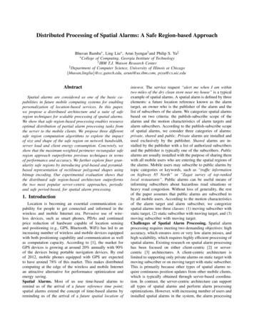
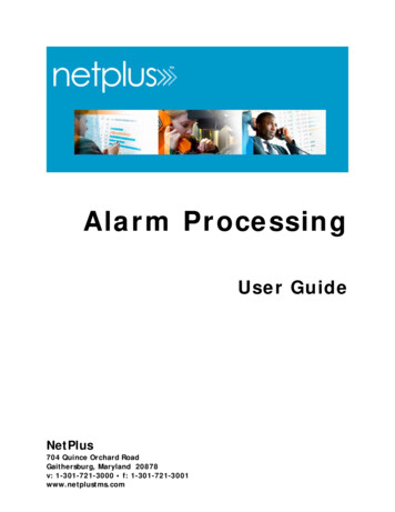
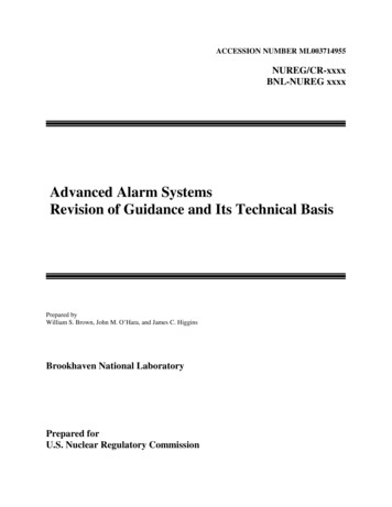
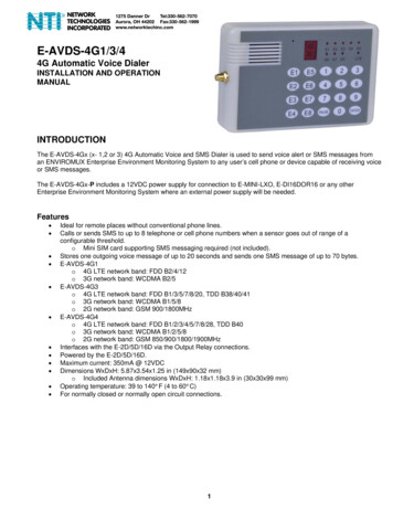
International Conference on Computing in High Energy and Nuclear Physics 2012 (CHEP2012) IOP PublishingJournal of Physics: Conference Series 396 (2012) 012038doi:10.1088/1742-6596/396/1/012038The main purpose of the CMS alarm and error system is to alert the operator when an abnormaloperation occurs, but also to keep history of all past problems for post mortem analysis. The presenteddesign is based on four powerful concepts: only notify important conditions, notify in time, respond,and provide guidance. The suggested infrastructure fits these needs by providing a set of expandableand reusable solutions allowing use of the alarming system for development, test and operationscenarios.2. Architecture and designThe architecture is based on the XDAQ Monitoring & Alarming Service (XMAS) [9], which providesseveral plug-ins specialized for specific tasks and services to support and implement a fully scalabledistributed monitoring and alarming system. It is a service-oriented architecture, in which a 3-tierstructured collection of communicating components cooperates to perform the monitoring, error andalarm management tasks. The XDAQ middleware provides the universal application connectivity andmakes applications and services inter-communicating [10] [11].Figure 1. Diagram is showing the XMAS components used for reporting (Sentinel), collecting(Eventing), recording (Spotlight), and display (Hotspot and Coldspot) of errors and alarms.As shown in Figure 1, the system builds upon a scalable publisher-subscriber [12] serviceconsisting of a pool of eventing applications orchestrated by a load balancer application (broker).When a DAQ application detects an anomaly it acts as data producers through sentinel services topublish an error or an alarm to the eventing service. The spotlight service is responsible for collecting,processing, and storing events. It subscribes to the eventing service specifying categories of error andalarm events it wants to receive. The spotlight supports two databases technologies: Oracle [13] forCMS production system and sqlite [14] for testing and small setups. The visualization components arecalled Hotspot and Coldspot, both applications are developed using Adobe Flash builder [15]. TheHotspot is used to visualize the error and alarm occurring in real-time using a graphical web interface.This application maps all occurring events and displays them according to a user-defined model of thesystem. The Coldspot allows querying spotlight through Query By Example [16] using a timewindow; this tool is used for post-mortem analysis.As shown in Figure 2, two different report scenarios can be identified: applications that detectpersistent deviations from the normal system behaviour report errors and deviations may also betransient, meaning an alarm is fired and eventually revoked when the asserted condition is resolved.2
International Conference on Computing in High Energy and Nuclear Physics 2012 (CHEP2012) IOP PublishingJournal of Physics: Conference Series 396 (2012) 012038doi:10.1088/1742-6596/396/1/012038Figure 2. Error and alarm interaction diagram.All services are re-locatable and run independently of each other without a need for externalcontrol. Communication among services is established through a rendezvous mechanism with the helpof discovery services facilities [17].3. Error handlingThe XDAQ environment offers developers programmatic tools to deal with errors as they occur atruntime. A uniform approach is used to handle exceptions in every application.//XCEPT RETHROW MACROtry {. some operation .} catch (std::exception& e) {XCEPT RETHROW(xoap::exception::Exception,”Text message”,e);}//XCEPT RAISE MACROXCEPT RAISE(xdaq::exception::Exception,”Text message”);//XCEPT ASSERT MACROXCEPT ASSERT(contextURL ! “”,xdaq::exception::BadCommand,”Text message”);//XCEPT DECLARE MACRO//Create a new exception and use it as a variable called exXCEPT DECLARE(b2in::nub::exception::Exception,ex,”Text message”);//XCEPT DECLARE NESTED MACRO//Create a new exception from a previous one and use it as a variable called extry {. some operation .} catch (b2in::nub::exception::Exception& e) {XCEPT DECLARE(b2in::nub::exception::Exception,ex,”Text message”,e);}Figure 3. Special macro instructions to throw an exception.The exception handling mechanism available to C programs provides the basic ways of dealingwith exceptional condition within an application “try/catch” and “throw” statements. The “throw”statement is replaced by special macro instructions (see Figure 3) that allow automatically building3
International Conference on Computing in High Energy and Nuclear Physics 2012 (CHEP2012) IOP PublishingJournal of Physics: Conference Series 396 (2012) 012038doi:10.1088/1742-6596/396/1/012038exception objects with run-time and compile time information. The mechanism is further enhanced toprovide an additional “re-throw” statement that allows to build the full sequence of subsequent“throw” of exceptions namely the exception stack trace.In this schema all errors and alarms are specified according to uniform approach by defining a C class that extends the standard “xcept::Exception”, as shown in Figure 4. A “xcept::Exception” objectencapsulates information specific to an error occurring in the distributed environment, e.g. the stack,subsystem, pc, application identifier etc. An exception can be thrown several times and propagate tothe function callers. The last function can catch this exception and perform some recovery or reportingactions.#ifndef jobcontrol exception Exception h#define jobcontrol exception Exception h#include "xcept/Exception.h"namespace jobcontrol {namespace exception {class Exception: public xcept::Exception{public:Exception( std::string name, std::string message, std::string module, int line,std::string function ):xcept::Exception(name, message, module, line, function){}Exception( std::string name, std::string message, std::string module, int line, std::string function,xcept::Exception & e ):xcept::Exception(name, message, module, line, function, e){}};}}#endifFigure 4. Declaration of an error for jobcontrol application.3.1. Sending error messagesReporting to external clients is eventually performed by calling the “notifiyQualified” method fromwithin any application. Figure 5 shows how to catch an error and append the exception trace to anewly created exception that will be reported.try{. some operation .} catch (toolbox::exception::Exception& exceptionObj){std::stringstream msg;msg "An error has happened that cannot be handled by the application";XCEPT DECLARE NESTED(xmas::sensor::exception::Exception, errorObj, msg.str(), exceptionObj);this- notifyQualified("fatal", errorObj);return;}Figure 5. Example how to send an error after catching an exception.3.2. Alarm messagesAlarm objects are treated similarly to ordinary errors with the exception that alarms can be transientand therefore revoked by the originator within a given period of time. This means that any instance of“xcept::Exception” object or a derived class can be used to represent an alarm, as shown in Figure 6.Such an alarm object can be given to the Sentinel application component within an XDAQ executivecontainer (context). Sentinel then takes care of routing this alarm through a publisher/subscribercomponent to the Spotlight error server that persistently stores the alarm and serves it to other clients.Alarms are resent periodically by the Sentinel application component until the alarm is revoked.4
International Conference on Computing in High Energy and Nuclear Physics 2012 (CHEP2012) IOP PublishingJournal of Physics: Conference Series 396 (2012) 012038doi:10.1088/1742-6596/396/1/012038#ifndef sentinel tester exception TestAlarm h#define sentinel tester exception TestAlarm h#include "sentinel/exception/Exception.h"namespace sentinel {namespace tester {namespace exception {class TestAlarm: public sentinel::exception::Exception{public:TestAlarm( std::string name, std::string message, std::string module, int line, std::string function):sentinel::exception::Exception(name, message, module, line, function){}TestAlarm( std::string name, std::string message, std::string module, int line, std::string function,xcept::Exception& e ):sentinel::exception::Exception(name, message, module, line, function, e){}};}}} #endifFigure 6. Example of an alarm for an XDAQ application.Figure 7 shown how to emit and revoke an alarm object. Before enabling an alarm the first actionis to retrieve an infospace called “alarms”. This infospace remembers all fired alarms locally and isused to re-emit the alarms. It is the communication interface between XDAQ applications and theSentinel subsystem for alarms. Using “XCEPT DECLARE” macro an instance of the previouslydefined alarm class is created. Next the alarm that derives from an “xcept::Exception” and thereforerepresents an error object is embedded in a “sentinel::utils::Alarm” object. It is possible to providethe severity (warning, error, and fatal) of the alarm as the first parameter. The second parameter is theerror object to be embedded and the third parameter points to the XDAQ application that is the creatorof this alarm. Then the alarm is fired into the infospace by giving it an unique name, test-alarm in ourexample.#include oSpace* is xdata::getInfoSpaceFactory()- get("urn:xdaq-sentinel:alarms");std::stringstream msg; msg "A test alarm has been emitted";XCEPT DECLARE(sentinel::tester::exception::TestAlarm, ex, msg.str());sentinel::utils::Alarm * alarm new sentinel::utils::Alarm("warning",ex, this);is- fireItemAvailable ("test-alarm", alarm);xdata::InfoSpace* is xdata::getInfoSpaceFactory()- larm * alarm dynamic cast sentinel::utils::Alarm* (is- find("test-alarm"));is- fireItemRevoked("test-alarm", this);delete alarm;Figure 7. Example how to emit and revoke an alarm object.Revoking an alarm works by retrieving the previously raised alarm from the infospace by thealarm's name ("test-alarm"in our example) and the ownership of the alarm stays with the application.Thus, the application has to take care of deleting the alarm object, either by keeping a reference to it orby retrieving it from the infospace. After you have retrieved the alarm, it is revoked from theinfospace. That will tell Sentinel to emit a revoke message to the spotlight server and to stop sendingthe alarm over and over.3.3. CommunicationsAll error and alarm objects are serialized into SOAP messages for communication over the networkaccording to the XSD schema as defined in Figure 8 that describes the XML content to be embeddedin a message. A binary serialization according the same semantic schema is also supported when highperformance and scalability are required.5
International Conference on Computing in High Energy and Nuclear Physics 2012 (CHEP2012) IOP PublishingJournal of Physics: Conference Series 396 (2012) 012038doi:10.1088/1742-6596/396/1/012038Figure 8. XML schema for notify SOAP message.As shown at the top of Figure 8 the notify message contains one or more errors, the error schemahas attributes and elements to describe a generic error and can include one or more nested errors. Themost important fields for the schema are the following: identifier is an identification of the exception class (e.g. jobcontrol::exception::JobCrash); notifier is the originator of this error message; dateTime is the time when the error occurred; severity is the level of error gravity (e.g. warning, fatal, and error); message is a textual description of the error details; tag is a special parameter. It carries application-level, end-to-end agreed information thatallows to efficiently display the information on the user interface side; uniqueid is universally unique identifier (UUID [22]) for identifying an instance of anerror.The Error schema contains the any tag that permits the extension of the schema with user specificerror information allowing the possibility to reuse the generic part of the schema maintaining the coreerror information. For the CMS data acquisition system the standard error has been extended with anadditional schema: ApplicationErrorRecordGroup for XDAQ application software. This schemadefines eight additional fields: class is the type or name of the described application (the fully qualified classname, e.g.ns1::ns2::MyClass); context is an URL of the applications container (e.g. http://HOST:PORT); group is the comma separated list of groups to which an application belongs; id is a numeric identifier for the application, for XDAQ the "lid" that identifies theapplication within its executive container; instance is the object instance of the application class; service is a textual identifier of the service that this application provides; uuid is the uniform unique identifier of this application instance; zone is the zone to which this application belongs, i.e. the partition identifier when multipartitions are used.4. VisualizationIn the CMS error and alarm system there are two different visualization scenarios to support theoperation of the CMS experiment: an online display and a post-mortem display. The CMS operatorsuse the online display during data taking to detect deviations from the normal system behaviour. TheCMS experts are able to analyze past errors using the post-mortem display.4.1. Online display model and graphicsThe system model provides an abstract view of the system. Several perspectives can be used torepresent different views of the system. A view can be defined as a recursive hierarchical structure tofulfill the system required. In order to match errors reported by the running system with the abstractmodel a number of filters are defined. Filters are associated with views by means of special nodes;named “filter nodes”. These nodes define regular expressions matching the attributes from the errorreport.6
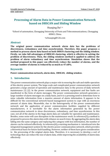
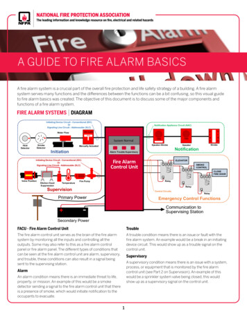
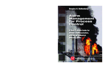
International Conference on Computing in High Energy and Nuclear Physics 2012 (CHEP2012) IOP PublishingJournal of Physics: Conference Series 396 (2012) 012038doi:10.1088/1742-6596/396/1/012038Figure 9. FEDBuilder class model. Blue boxes are different viewsinstead the dashed red boxes are filter nodes used by connected views.Figure 9 shows the FEDBuilder class tree model structure. The FEDBuilder refers to a set ofapplications that are logically grouped together. In this model the association between fedbuilder A and crateid can change in each configuration of the DAQ system. Therefore a model is derivedfrom the configuration database. The following attributes (see Table 1) must be defined to intercepterrors from all applications participating in the FEDBuilder task, they are used to intercept and countthe exceptions and map them to the system tree model.Table 1. Fedbuilder attributes.NameChannel C RU on slice S OtherGroupunit frlcrate, crate crateid Taggeoslot G , channel C unit ru,fb A , slice S unit frlcrate, crate crateid Hotspot is an Adobe Flex [18] application used to view and retrieve the error and alarm data storedand retrieved by Spotlight. Hotspot displays errors and alarms according the CMS data acquisitionabstract model system. Errors and alarms are associated to elements of the system model anddisplayed corresponding to their severity levels. The tool offers different views of the model such astree navigation, heat maps, and tables. Figure 10 shows the main view of Hotspot, the left-most panelof the main view represents the model tree that categorizes errors into nodes within the tree. Thenodes are categorized under labels such as ‘Fedbuilders’, ‘FEDs’, ‘Slices’, ‘Infrastructure’, and so on.These categories are represented as tiles on the right-most panel in the Heatmap. Each tile on theheatmap displays the name of the category it represents, its associated icon and, if existing, anyexceptions associated with it.The coloured bar represents the severity level of the most-severe exception contained, in ourexample there are Fedbuilder error exceptions and the bar is orange. Double-clicking on a heatmap tilebrings the heatmap to focus on the nodes and subcategories within it allowing the user to navigate andrefine his criteria for viewing exceptions. The user is also able to select elements on the model tree toaccomplish the same effect. Selecting an element on the model tree and clicking “Acknowledge”allows the user to acknowledge (dismiss) all the exceptions categorized within that element. The“Reset” button removes all the exceptions being displayed on the screen and triggers a reloading of themodel definition XML file – resetting the application to a state as if it had just been launched. InFigure 10, a fedbuilder::exception::DataCorruptionDetected error matches two different views: the“Fedbuilders” and the “Slices” perspectives. Clicking ‘Info’ on a heatmap tile or clicking the ‘Info’ tabnavigates to view the selected exceptions and their properties. Figure 11 displays the exceptionsselected under the previous Hotspot main view. This view allows the user to selectively acknowledge7
International Conference on Computing in High Energy and Nuclear Physics 2012 (CHEP2012) IOP PublishingJournal of Physics: Conference Series 396 (2012) 012038doi:10.1088/1742-6596/396/1/012038individual exceptions and identify their structure (as relating to parent and child exceptions), and theirassociated properties such as their severity, notifying application, error message etc.Figure 10. Main view of the Hotspot application.4.2. Post-mortem analysis and graphicsColdspot is an Adobe Flex application providing a post-mortem view of exception data stored byspotlight. The main feature is to retrieve the error through Query By Example using a time window.The “Query” tab of the coldspot allows the user to selectively choose each parameter to perform thequery. The time window in which errors should be searched for can be specified by the controls at thetop of the tab, by clicking the “submit” button the query is sent to the spotlight. The “display” tabdisplays the exceptions retrieved from the spotlight application with the same interface look and feelof the Hotspot “Info” tag (see Figure 11).5. PersistencyThe spotlight application is responsible for the storage and retrieval of error and alarm data. Threespotlight applications have been implemented to support different requirements: Spotlight2g, utilizes a database called SQLite to store the exceptions. SQLite is a in-processlibrary that implements a self-contained, server-less, zero-configuration, and transactionalSQL database engine. It is a very lightweight database, however it is unable to efficientlyhandle large datasets. To compensate for this, an archival system is required to record the datasplit across multiple database files. This was an early implementation for initial developmentas a proof of concept and now it is used for testing and small setups; SpotlightOCCI, making use of Oracle’s OCCI API, is used to store this exception data in anOracle database. The Oracle database has no upper-limit to the amount of data it can store andit has been shown to cope and operate smoothly with hundreds of thousands of records ofexception data. The Oracle database is also a very widely used and robust RDBMS withthorough documentation, these features combining to make it a more suitable technology forrecording the exceptions than the SQLite. This is used in the CMS production system.8
International Conference on Computing in High Energy and Nuclear Physics 2012 (CHEP2012) IOP PublishingJournal of Physics: Conference Series 396 (2012) 012038doi:10.1088/1742-6596/396/1/012038Figure 11. Hotspot application “Info” tab. SpotlightTT, utilized an in-memory database called Oracle TimesTen [19]. This database isdesigned for low latency, high-volume data, event and transaction management. BecauseTimesTen’s data is stored entirely in memory, no disk I/O operations are required whenprocessing queries. Since memory access is much quicker than disk access, TimesTen is oftenused in situations that demand a fast and predictable response time, such as intelecommunications systems and financial transaction services. TimesTen supports standardANSI SQL (in addition to its own commands for setup and administration) and can beaccessed through standard ODBC and JDBC, or through the provided Oracle APIs (such asOCCI). TimesTen’s primary limitation is the memory capacity available on the host machine.Because all TimesTen’s data is held in memory, the amount being stored cannot be greaterthan the memory space made available by the operating system.6. BenchmarksIn the CMS error and alarm system the latency for reporting an error from user application to spotlightit is less then one second with the current DAQ system. The scalability of the system is achieved withincreasing the number of spotlight applications. The maximum performance for the spotlightapplication depends on the database capabilities. SpotlightOCCI has been measured to be capable toperform at approximately 600 Hz (insertions per second). TimesTen is an in-memory implementationof Oracle database, and stores database data in a machine’s RAM as opposed to hard disk for quickeraccess. By caching the data in memory, data can be accessed and modified more quickly. Using aTimesTen memory cache, spotlightTT was able to perform approximately at 2kHz. Spotlight2g, forcomparison, stored approximately 1kHz insertions per second.9
International Conference on Computing in High Energy and Nuclear Physics 2012 (CHEP2012) IOP PublishingJournal of Physics: Conference Series 396 (2012) 012038doi:10.1088/1742-6596/396/1/012038Figure 12. Central XaaS.7. Integration with CMS sub-detectorsThe CMS sub-detectors use XDAQ framework to develop the online software needed for the datataking, and are responsible to bring data from their sub-detector front-end system to front-end drivers.Different teams are involved in developing the sub-systems software and alternative approaches aretaken for the same problem. One example is the error reporting: storing errors in a local disk,collecting logs in a central place etc. The central DAQ group aims to standardize the error and alarmmanagement for all CMS online systems. To succeed it is not enough to provide a common softwarebut a common infrastructure is also needed, to cope with this problem the XDAQ as a Service (XaaS)has been designed based on the software as a service concept [20].XaaS is a full set of interoperable services that provide standard functionalities for use in the XDAQenvironment. A XDAQ zone defines the scope of a distributed XDAQ application and all processesare organized into and searchable groups known as zones. Each zone has its own error database,monitoring data types, and error report system model. An independent dedicated XaaS is available foreach different XDAQ zone. Each CMS sub-detectors should have a XaaS infrastructure maintained bythe central DAQ team and a central XaaS system could collect error and alarm from all the CMSexperiment as shown in Figure 12.8. SummaryThe error and alarm system has been implemented and is currently used in an operational environmentfor the central DAQ and almost all CMS sub-detectors. This software product line [21] is the result ofseveral years of development and has proven its fitness for operation in the last three years of LHCoperation. This paper summarized key requirements and outlined the resulting architecture (errorhandling, visualization, persistency, and integration) of the Distributed error and alarm processing inthe CMS data acquisition system.AcknowledgementsThis work was supported in part by the DOE and NSF (USA) and the Marie Curie Program.10
International Conference on Computing in High Energy and Nuclear Physics 2012 (CHEP2012) IOP PublishingJournal of Physics: Conference Series 396 (2012) [1] The CMS Collaboration, The Compact Muon Solenoid Technical Proposal, CERN/LHCC94-38(1994)[2] The LHC Study Group, The Large Hadron Collider Conceptual Design Report, CERN/AC95-05(1995).[3] The CMS Collaboration, The Trigger and Data Aquisition project, CERN/LHCC 2002-26, 15December 2002.[4] Antchev G et al 2001, The Data Acquisition System for the CMS Experiment at LHC in Proc.7th Intl. Conf. Adv. Tech. and Particle Phys. Villa Olmo, Como, Italy (Oct. 15-19, 2001)World Scientific Publishers (ISBN 981-238-180-5)[5] Bauer G et al 2008 CMS DAQ Event Builder Based on Gigabit Ethernet IEEE Trans. Nucl. Sci.55(1) 198-202[6] Gutleber J, Murray S, Orsini L 2003 Towards a homogeneous architecture for high-energyphysics data acquisition systems Elsevier Comp. Phys. Comm. 153(2) 155-163[7] Parnas D L 1979 Designing Software for Ease of Extension and Contraction, IEEE Trans.Softw. Eng SE-5(2) 128-137[8] Grama A Y, Gupta A and Kumar V 1993 Isoefficiency: measuring the scalability of parallelalgorithms and architectures, IEEE Par. & Distr. Tech.: Systems & Applications 1(3) 12-21[9] G Bauer et al 2010, Monitoring the CMS Data Acquisition System, J. Phys.: Conf. Ser. 219022042[10] Parnas D L 1979 Designing Software for Ease of Extension and Contraction, IEEE Trans.Softw. Eng SE-5(2) 128-137[11] Nierstrasz O, Gibbs S and Tsichritzis D 1992 Component-oriented software developmentComm. ACM 35(9) 160-164[12] Birman, K. and Joseph, T., Exploiting virtual synchrony in distributed systems in Proceedingsof the eleventh ACM Symposium on Operating systems principles (SOSP '87), 1987. pp. 123138.[13] Oracle database, tml?ssSourceSiteId otnen[14] SQLite database, http://www.sqlite.org/docs.html[15] Adobe Flash Builder, 6] M. Zloof. Query by Example. AFIPS, 44, 1975.[17] Guttman E, Perkins C, Vaizades J and Day M 1999 Sevice Location Protocol Version 2 InternetRFC http://www.ietf.org/rfc/rfc2608.txt[18] Adobe Flex, http://www.adobe.com/products/flex.html[19] Oracle TimesTen In-Memory Database, n066524.html[20] Software As A Service: Strategic Backgrounder. Washington, D.C.: Software & InformationIndustry Association. 28 February 2001[21] Clements P, Northrop L 2002 Software Product Lines Addison-Wesley (ISBN 0-201-70332-7)[22] Universally unique identifier, http://en.wikipedia.org/wiki/Universally unique identifier11
alarm's name ("test-alarm"in our example) and the ownership of the alarm stays with the application. Thus, the application has to take care of deleting the alarm object, either by keeping a reference to it or by retrieving it from the infospace. After you have retrieved the alarm, it is revoked from the infospace. That will tell Sentinel to emit a