Transcription
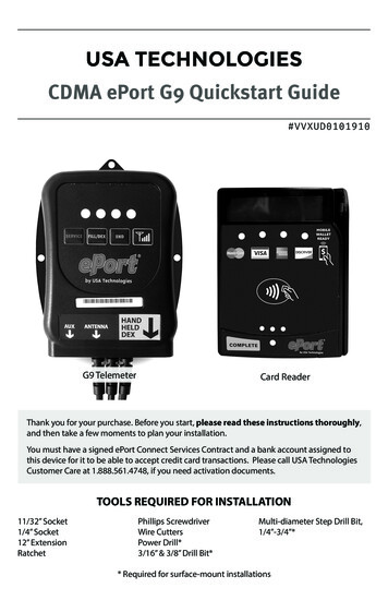
USA TECHNOLOGIESCDMA ePort G9 Quickstart Guide#VVXUD0101910G9 TelemeterCard ReaderThank you for your purchase. Before you start, please read these instructions thoroughly,and then take a few moments to plan your installation.You must have a signed ePort Connect Services Contract and a bank account assigned tothis device for it to be able to accept credit card transactions. Please call USA TechnologiesCustomer Care at 1.888.561.4748, if you need activation documents.TOOLS REQUIRED FOR INSTALLATION11/32” Socket1/4” Socket12” ExtensionRatchetPhillips ScrewdriverWire CuttersPower Drill*3/16” & 3/8” Drill Bit*Multi-diameter Step Drill Bit,1/4”-3/4”** Required for surface-mount installations
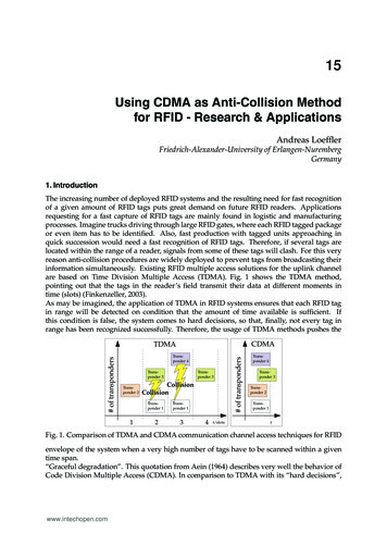
INSTALLATION PROCEDURES FOR THE G9 EPORTThe G9 ePort works in vending machines with one or two full bill acceptor openings,allowing the acceptance of credit/debit transactions by using Card Swipe or RF technology payments. The G9 ePort solution works with the MDB vending interface. Additionally, the G9 has interfaces for Coin Pulse systems, along with a serial interface for PCbased systems. In both Coin Pulse and Serial Modes, parameters can be modified tomeet design requirements.KIT CONTENTSYour CDMA Wireless G9 ePort kit includes (Shown in Figure 1 unless noted): One G9 Telemeter with wireless modem installed (#VVWUT0101901) One Card Reader (Bezel) (#V8SUK1235003) One Flange Mount Plate (#V6XUE1520259) One Bezel Drilling Template One Bezel Adapter Cable (#V6SUC1435003) One Magnetic Base Antenna (#V8WUP0101278) Mounting Hardware: Four, 8-32 x 3/8” screws for mounting reader, and three selfdrilling screws (#DCHZDHH62006) NOT PICTURED: Various POS stickers, Troubleshooting Checklist (#V8VUD1101435),RMA Procedure Sheet (#UXXUD0101552), this install guide (#VVXUD0101910), twoVelcro strips, six Wire Ties for the Card Reader, and additional order itemsBEFORE YOU START, read the instructions and take a few moments to plan your installation. Pick a mounting spot for the G9 Telemeter that will allow for ease of access anddoes not interfere with any moving parts in your vending equipment.FIGURE 1 (items not to scale)G9 Telemeter#VVWUT0101901Card Reader (Bezel)#V8SUK1235003Bezel Adapter Cable#V6SUC14350032Magnetic BaseAntenna#V8WUP0101278Flange Mount Plate#V6XUE1520259Bezel DrillingTemplateMounting Hardware #DCHZDHH62006Four, 8-32 x 3/8” mounting screws, three self-drilling screws.
1. RSSI SIGNAL STRENGTH TESTING PROCEDUREParts Required for RSSI Test: G9 Telemeter and a Magnetic Base AntennaOptional: A Card Reader and a High Gain Antenna (see note) of 4’ or 8’ cable length(#VXWUP1101284 or #VXWUP3101284, respectively)An RSSI test is done to determine if there is acceptable signal strength at a location before installing. The test also helps to place the antenna for the best reception. Wherethe antenna receives the best signal will also determine where to mount the Telemeter.NOTE: A High Gain Antenna should be on hand in the event that the included Magnetic Base Antenna is unable to pick up a sufficient signal. A High Gain Antenna mustbe purchased separately as it is not included with the kit.1. A t the machine location, plug the antenna’s cable into the ANTENNA port foundon the bottom of the G9 Telemeter. If a Card Reader is present, plug the serialcable from the Card Reader into the Telemeter cable’s 6-pin black connector.2. D isconnect the MDB connectors in the vending machine between the machinecontrol board and the bill acceptor and connect the MDB Cable* from the G9 Telemeter to the MDB connectors of the vending machine.3. P lace the antenna on top of, or inside the vending machine on a metal surface toperform the test. Make sure the antenna is not surrounded by signal weakeningmetal support brackets or located near the Telemeter or the control board whenthe door is shut. This will improve connectivity to the cellular tower.4. Wait until the Telemeter has initialized, which is indicated by a blinking green LED.If a Card Reader is present the display will read “Swipe or Tap to Begin.”5. To begin testing, press the Telemeter’s RSSI buton. The Telemeter’sLEDs will indicate signal strength. And if present, the Card Reader’sdisplay will show CSQ: XX, YY; where XX is signal strength and YY isBit Error Rate. Use the following table to determine signal quality.QUALITYTELEMETER LEDsCSQ: XXVery poornone00 to 07PoorRED08 to 09GoodRED and YELLOW10 to 14Very goodRED, YELLOW and GREENExcellentRED, YELLOW, GREEN and BLUE15 to 19RSSI ButtonCSQ: YYAny value otherthan 00 for CSQ:YYindicates additional signal loss.20 or greater6. If signal strength is poor or very poor, move the antenna to another location andwait 15 seconds until the signal stabilizes and then recheck. If signal strength isnot strong enough with the normal Antenna, try the test with a High Gain Antenna.7. Upon completion of testing, disconnect the G9 Telemeter’s MDB cable and reconnect the vending machine MDB connectors.* When a Bill Recycler is present, the ePort must be plugged into the MDB bus ahead of theBill Recycler to receive enough power to function properly.3
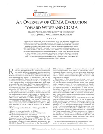
2. RF/CARD SWIPE READER INSTALLATIONInstall the Card Reader according to the design of the vending machine:ABCDAMachine has a second opening for a bill acceptor - take note of screw sizes.Machine does not have a second opening for a bill acceptor.Machine has a POS window above the bill acceptor.Machine has a situation where a spacer is needed.Vending machine has a second opening for a bill acceptorOPTIONAL SPACER1. Power down the vending machine door and removethe blank plate that covers the opening.2. Attach the Card Reader to the mounting plate usingthe four, 8-32 x 3/8” mounting screws.Correct screws must be used or the Card Readermay be damaged and the warranty will be void.3. Pass the assembly through the opening from insidethe door of the vending machine and secure themounting plate to the door with the original, blank plate screws.BFIGURE 2Vending machine does not have a second opening for a bill acceptorMount the Card Reader on the outside surface of the vending machine:1. Power down the vending machine door. If necessary, temporarily remove the billacceptor during the drilling and mounting of the Card Reader.2. Use a small level and tape to secure the included Bezel Drilling template (Figure1) where you want the Card Reader to be located, and mark the four mountingscrew holes and a hole for the cable.4. Drill the four 3/16” holes for the mounting screws.5. Drill the pilot hole for the 5/8” cable hole with a 3/8” bit and finish the hole byusing either a 41/64” Greenlee knockout punch (#7211BB-1/2) or a 1/4”–3/4” stepdrill (McMaster-Carr part 8841A23).6. Mount the Card Reader to the front of the door by using the four, 8-32 x 3/8”mounting screws.C4 ending machine has a POS window above the bill acceptorV If the vending machine (i.e. the Royal 660, Royal 804, or the Dixie 522) has a POSwindow just above the bill acceptor (landscape doors), you must install the CardReader with the Security Plate (#V6XUE0520260). A Security Plate is not included in the kit and can be purchased separately.
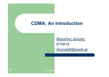
1. Power down the vending machine.FIGURE 32. Remove the bill acceptor.3. Remove the POS window above the billacceptor.5. Secure the security plate to the CardReader with four, 8-32 x 3/8” mountingscrews (Figure 3).8-32 x 3/8”screwsREADER4. Route the serial cable attached to the backof the Card Reader through the securityplate (Figure 3).SECURITYPLATE6. Pass this assembly through the POS window opening from inside the vending machine door, and attach the security plateto the door using the original hardware.BezelAdapterCable7. Replace the bill acceptor.Vending machine has a situation where a spacer is neededSome machines may require a spacer for the Card Reader to provide properclearance for card swipes. If this is the case, a spacer and four, 8-32 x 1” long screws areavailable from USA Technologies by contactFIGURE 4ing Customer Service at 888-561-4748. Re8-32 x 1”quest Spacer (#V6SUF1435002) and the four,screws8-32 x 1” screws that are the correct lengthfor an installation with a spacer. A cost is associated with this part.SPACERTo complete the install, follow either the A,B or C instructions above depending on thedesign of the vending machine, and placethe spacer between the cardreader and platespecific to the install and use the the four,8-32 x 1” screws.READERDAlignmentPinsBezelAdapterCable5
3. INSTALL THE G9 TELEMETERFollow these steps to install the G9 Telemeter in a vending machine:1. Decide whether to mount the Telemeter usingthe three supplied self-tapping screws (Figure5), or with a strip of Velcro attached to theback of the Telemeter.FIGURE 52. Select a location in the main cabinet or doorwhere the Telemeter is accessible for serviceand protected from moisture. To prevent anywater intrusion, mount the Telemeter vertically with the cables hanging down. Makesure it will not interfere with any moving partsand allow for cable routing.3. If mounting with screws, screw the selftapping screws into the frame of the door ormachine. If using Velcro, attach a strip of Velcroto the frame of the door or machine and stickthe Telemeter to it.FIGURE 64. Connect the Magnetic Base Antenna (#V8WUP0101278) MCX connector into the ANTENNAports found on the bottom of the Telemeter.5. Place the antenna on top of, or inside the vending machine on a metal surface. Make sure theantenna is not surrounded by signal weakening metal support brackets or located near theTelemeter or the control board when the dooris shut. This will improve connectivity to thecellular tower. (Figure 6).5. Tie the antenna cable to the nearest cable from the Telemeter.6. Disconnect the MDB connectors in the vending machine between the machineControl Board and the existing payment devices. Connect the MDB Cable fromthe G9 Telemeter to the MDB connectors going to the machine Control Board andthe existing payment devices. Ensure the connectors latch firmly together.*7. Plug the 6-pin black connector from the Telemeter cable into the serial cable fromthe Card Reader. Ensure the connectors latch firmly together.8. Either connect the DEX cable with the standard jack plug from the Telemeter tothe vending machine DEX port (for remote DEX reporting), or leave the DEX cablehanging loose if no remote DEX is to be used. Test all connections made.*NOTE: When a Bill Recycler is present, the ePort must be plugged into the MDB busahead of the Bill Recycler so that it can communicate properly with the VMC.6
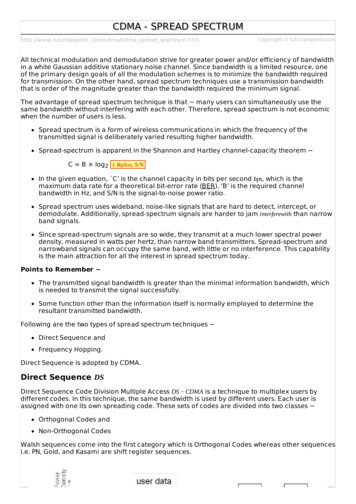
FIGURE 7 G9 C0NTROLLER CABLESDEX CableSerial CableMDB Cable4. VERIFY THE INSTALLATION1. Power up the vending machine and observe the LEDs of the G9 Telemeter. Whenthe green LED blinks, the Telemeter has initialized.2. Once the Telemeter has initialized the HSPA Modem and connected to the wireless network, the Card Reader’s display should read “Swipe or Tap To Begin. “3. At this point you can perform a test vend with a USA Technologies Pass Card orcredit card.4. We recommend recording the ePort G9 Telemeter serial number and vendingmachine ID for accounting purposes.5. Contact USAT Customer Care if you have any questions – 888-561-4748.You must have a signed ePort Connect Services Contract and bank account assigned to this device for it to be able to accept credit card transactions. Pleasecall USA Technologies Customer Care at 888-561-4748, if you need activationdocuments.7
3103 Phoenixville PikeMalvern, PA 19355USA TECHNOLOGIES CUSTOMER CAREContact USA Technologies Customer Care for technical support and to requestadditional parts, information, and pre-authorization forms.Phone: 888.561.4748FAX: 610.989.9695Email: customersupport@usatech.comOnline Store: http://store.usatech.comUSA TECHNOLOGIES WEBSITE ADDRESSESCustomer Website Loginhttps://usalive.usatech.comCompany Sitehttp://www.usatech.comThis device complies with Part 15 of the FCC Rules. Operation is subject to the following two conditions:1. This device may not cause harmful interference2. This device must accept any interference received, including interference that may causeundesired operation.#VVXUD0101910 REV CAll contents Copyright 2017 USA Technologies, Inc.All rights reserved.
INSTALLATION PROCEDURES FOR THE G9 EPORT The G9 ePort works in vending machines with one or two full bill acceptor openings, allowing the acceptance of credit/debit transactions by using Card Swipe or RF technol-ogy payments. The G9 ePort solution works with the MDB vending interface. Addition-