Transcription
Network Virtualization inMulti-tenant DatacentersTECHNICAL REPORTTR-2013-001ETeemu Koponen, Keith Amidon, Peter Balland, Martín Casado, Anupam Chanda,Bryan Fulton, Igor Ganichev, Jesse Gross, Natasha Gude, Paul Ingram, Ethan Jackson,Andrew Lambeth, Romain Lenglet, Shih-Hao Li, Amar Padmanabhan, Justin Pettit,Ben Pfaff, Rajiv Ramanathan, Scott Shenker*, Alan Shieh, Jeremy Stribling,Pankaj Thakkar, Dan Wendlandt, Alexander Yip, Ronghua Zhang*International Computer Science Institute & UC Berkeley
Network Virtualization inMulti-tenant DatacentersAbstractMulti-tenant datacenters represent an extremely challenging networking environment. Tenants want the abilityto migrate unmodified workloads from their enterprise networks to service provider datacenters, retaining thesame networking configurations of their home network. The service providers must meet these needs withoutoperator intervention while preserving their own operational flexibility and efficiency. Traditional networkingapproaches have failed to meet these tenant and provider requirements. Responding to this need, we presentthe design and implementation of a network virtualization solution for multi-tenant datacenters.1 IntroductionThe work in this paper was necessitated by the merging of two technology trends. The first is the advent of largedatacenters. These were initially developed to support large in-house Internet services, but now are also used toprovide computing resources to others. These customers (or “tenants”, as we shall refer to them) can avail themselvesof a large and professionally managed computational infrastructure on an as-needed basis without investing thesignificant capital expense or obtaining the extensive operational expertise needed to run their own. However, if thiswere the entire story, tenants would have to manually port their computations to the cloud to gain these advantages.This barrier is largely removed by the second technology trend: virtualization. Modern hypervisors support virtualmachines (VMs) that provide faithful resource abstractions. In this manner, one can decouple the logical requirementsof the computation from the actual physical infrastructure that satisfies them. This decoupling is essential forallowing computations to run, without modification, either locally or in the cloud.The combination of these two trends—datacenters and virtualization—has led to an increasing number of largemulti-tenant datacenters (MTDs) where tenants can seamlessly deploy individual computations in the cloud.However, to fully move internal operations to the cloud—that is, not just individual VMs but an interacting set ofVMs connected by a nontrivial network—MTDs must provide faithful abstractions for all relevant resources in amodern enterprise environment. Computation and storage have long been successfully abstracted in modernhypervisors; however, networking services have not, since tenants are not typically given the ability to managethe cloud’s networking resources. Thus, networking is the last holdout in the virtualization revolution.From the tenants’ perspective, network virtualization should allow them to configure the way their VMs areconnected in the cloud much as they would configure the network in their own enterprise. From an MTD operator’sperspective, network virtualization should allow configuration of the physical network in a way that satisfiesall of the tenant-driven requirements, while giving the operator flexibility to deploy a wide range of physicalnetwork technologies and topologies.While a variety of techniques (e.g., VLANs) can isolate tenant traffic in a fairly static manner, there are no currentlyavailable techniques for providing the full generality of network virtualization we consider here. Thus, the goal ofthis paper is to provide the first in-depth discussion of how one supports network virtualization in an MTD. Oursolution uses Software-Defined Networking (SDN) as a base technology, and our innovations include a networkhypervisor built on top of an SDN controller cluster and various datapath enhancements. Our solution, which wewill refer to as the Network Virtualization Platform (NVP), has been in production use for two years.TR-2013- 001ETECHNICAL REPORT / 2
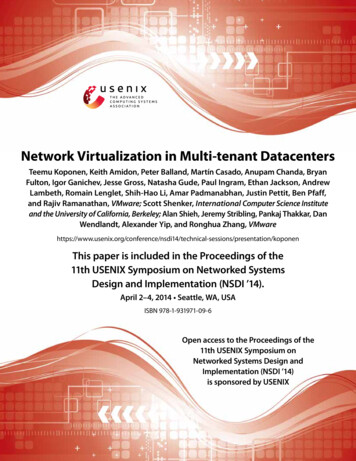
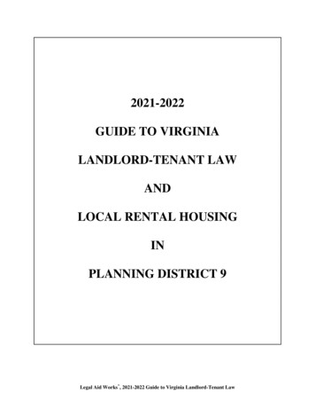
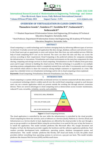
Network Virtualization inMulti-tenant Datacenters2 System DesignMTDs have a set of hosts connected by a physical network. Each host has multiple VMs supported by the host’shypervisor. Each host hypervisor has an internal software virtual switch that accepts packets from these localVMs and forwards them either to another local VM or over the physical network to another host hypervisor.Just as the hypervisor on a host provides the right virtualization abstractions to VMs, we build our architecturearound a network hypervisor that provides the right network virtualization abstractions. In this section we describethe network hypervisor and its abstractions.2.1 AbstractionsA tenant interacts with a network (both its home network, and the network in the MTD) in two ways: the tenant’sendpoints (e.g., hosts and/or VMs) send packets, and the tenant’s control plane (e.g., routing protocols, manualconfiguration) configures network elements (e.g., switches and routers). A service provider’s network consistsof a physical forwarding infrastructure and the system that manages and extends this infrastructure, which isthe focus of this paper.The network hypervisor is a software layer interposed between the provider’s physical forwarding infrastructureand the various tenant control planes. Its purpose is to provide the proper abstractions to a tenant’s controlplane and endpoints, and we describe these abstractions below:Control abstraction. This abstraction must allow tenants to define a set of logical network elements (or, as we shallcall them, datapaths) that they can configure (through their control planes) as they would physical network elements.Each logical datapath is defined by a packet forwarding pipeline interface that, similar to modern forwarding ASICs,contains a sequence of lookup tables, each capable of matching over packet headers and metadata established byearlier pipeline stages. At each stage, packet headers can be modified or the packet can be dropped altogether.The pipeline results in a forwarding decision, which is saved to the packet’s metadata, and the packet is then sentout the appropriate port. Since our logical datapaths are implemented in software virtual switches, we have moreflexibility than ASIC implementations; datapaths need not hardcode the type or number of lookup tables, andthe lookup tables can match over arbitrary packet header fields.Packet abstraction. This abstraction must enable packets sent by endpoints in the MTD to be given the sameswitching, routing, and filtering service as they would have in the tenant’s home network. This can be accomplishedwithin the packet forwarding pipeline model described above. For instance, to provide basic L2 forwarding semantics,the control plane could populate a single forwarding table with entries explicitly matching on destination MACaddress and sending the packets to ports connected to the corresponding VMs. Alternatively, the control planecould install a special learning flow that forwards packets to ports where traffic from the destination MAC addresswas last received (which will time out in the absence of new traffic) and simply flood unknown packets. Similarly,broadcast destination addresses are handled with a flow entry that sends packets to all logical ports (excludingthe port on which the packet was received) on the logical switch.2.2 Virtualization ArchitectureThe network hypervisor supports these abstractions by implementing tenant-specific logical datapaths on topof the provider’s physical forwarding infrastructure, and these logical datapaths provide the appropriate controland packet abstractions to each tenant.In our NVP design, we implement the logical datapaths in the software virtual switches on each host, leveraginga set of tunnels between every pair of host-hypervisors (so the physical network sees nothing other than whatappears to be ordinary IP traffic between the physical hosts). Almost the entire logical datapath is implementedon the virtual switch where the originating VM resides; after the logical datapath reaches a forwarding decision,the virtual switch tunnels it over the physical network to the receiving host hypervisor, which decapsulates thepacket and sends it to the destination VM (see Figure 1). A centralized SDN controller cluster is responsible forconfiguring virtual switches with the appropriate logical forwarding.TR-2013- 001ETECHNICAL REPORT / 3
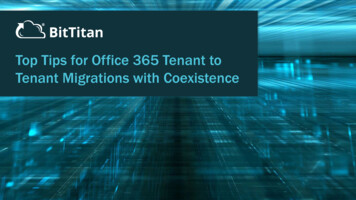
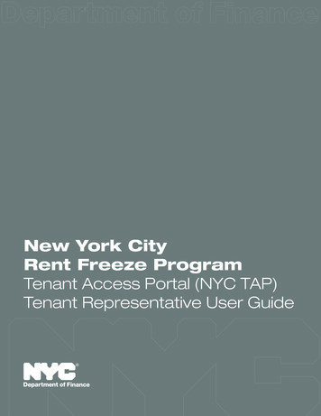
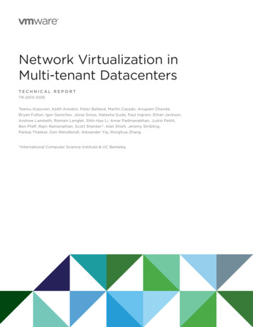
Network Virtualization inMulti-tenant DatacentersFigure 1. Logical forwarding is implemented by the virtual switch of the originating host hypervisor. After the logical forwarding decision is made, thepacket is tunneled across the physical network to the receiving host hypervisor for delivery to the destination VM.While tunnels can efficiently implement logical point-to-point communication, additional support is needed forlogical broadcast or multicast services. For packet replication, NVP constructs a simple multicast overlay usingadditional physical forwarding elements (x86-based hosts running virtual switching software) called servicenodes. Once a logical forwarding decision results in the need for packet replication, the packet is tunneled toa service node, which then replicates the packet to all host hypervisors that need a copy for their local VMs.In addition, some tenants want to integrate their logical network with their existing physical one. This is donethrough gateway appliances (again, x86-based hosts running virtual switching software); all traffic from thephysical network goes to the host hypervisor through this gateway appliance, and then can be controlled byNVP (and vice versa for the reverse direction). Gateway appliances can be either within the MTD or at thetenant’s remote site. Figure 2 depicts the resulting arrangement of host hypervisors, service nodes, andgateways, which we collectively refer to as transport nodes.Figure 2. In NVP, a controller cluster manages the forwarding state at all transport nodes (hypervisors, gateways, service nodes), but is not involved inpacket routing. Transport nodes are fully meshed over IP tunnels (solid lines). Gateways integrate the logical networks with physical networks, andservice nodes provide replication for logical multicast/broadcast.TR-2013- 001ETECHNICAL REPORT / 4
Network Virtualization inMulti-tenant Datacenters2.3 Design ChallengesThis brief overview of NVP hides many design challenges, three of which we focus on in this paper.Datapath design and acceleration. NVP relies on software switching. In Section 3 we describe the datapathand the substantial modifications needed to support high-speed x86 encapsulation.Declarative programming. The controller cluster is responsible for computing all forwarding state and thendisseminating it to the virtual switches. To minimize the cost of recomputation, ensure consistency in the faceof varying event orders, and promptly handle network changes, we developed a declarative domain-specificlanguage for the controller that we discuss in Section 4.Scaling the cluster computation. In Section 5 we discuss the various issues associated with scaling thecontroller cluster.After we discuss these design issues, we evaluate the performance of NVP in Section 6, discuss related workin Section 7, and then conclude in Section 8.3 Virtualization Support at the EdgeThe endpoints of the tunnels created and managed by NVP are in the virtual switches that run on host hypervisors,gateway nodes, and service nodes. We refer to this collection of virtual switches as the network edge. This sectiondescribes how NVP implements logical datapaths at the network edge, and how it achieves sufficient data planeperformance on standard x86 hardware.3.1 Implementing the Logical DatapathNVP uses Open vSwitch (OVS) [23] in all transport nodes (host hypervisors, service nodes, and gateway nodes) toforward packets. OVS is remotely configurable by the NVP controller cluster by two protocols: one that can inspectand modify a set of flow tables (analogous to flow tables in physical switches),1 and one that allows the controllerto create and manage overlay tunnels to transport nodes and discover which VMs are hosted at a hypervisor [22].The controller cluster uses these protocols to implement packet forwarding for logical datapaths. Each logicaldatapath consists of a series (pipeline) of logical flow tables, each with its own globally unique identifier. Thetables consist of a set of flow entries that specify expressions to match against the header of a packet, andactions to take on the packet when a given expression is satisfied. Possible actions include modifying a packet,dropping a packet, sending it to a given egress port on the logical datapath, and writing in-memory metadata(analogous to registers on physical switches) associated with the packet and resubmitting it back to thedatapath for further processing. A flow expression can match against this metadata, in addition to the packet’sheader. NVP writes the flow entries for each logical datapath to a single OVS flow table at each virtual switchthat participates in the logical datapath.Any packet entering OVS—either from a virtual network interface card (vNIC) attached to a VM, an overlaytunnel from a different transport node, or a physical network interface card (NIC)—must be sent through thelogical pipeline corresponding to the logical datapath to which the packet belongs. For vNIC and NIC traffic,the service provider tells the controller cluster which ports on the transport node (vNICs or NICs) correspondto which logical datapath ports (see Section 5); for overlay traffic, the tunnel header of the incoming packetcontains this information. Then, to connect each packet to its logical pipeline, NVP writes flows into the OVSflow table that match a packet based on its ingress port, and adds to the packet’s metadata an identifier forthe first logical flow table of the packet’s logical datapath. As its action, this flow entry resubmits the packetback to the OVS flow table to begin its traversal of the logical pipeline.1 We use OpenFlow [21] for this protocol, though any flow management protocol with sufficient flexibility would work.TR-2013- 001ETECHNICAL REPORT / 5
Network Virtualization inMulti-tenant DatacentersThe control plane abstraction that NVP provides internally for programming the tables of the logical pipelinesis largely the same as the interface to OVS’s flow table, and NVP writes flow entries directly to OVS, with twoimportant differences:đƫMatches. Before each logical flow entry is written to OVS, NVP augments it to include a match over the packet’smetadata for the logical table’s identifier. This enforces isolation from other logical datapaths and places thelookup entry at the proper stage of the logical pipeline. In addition to this forced match, the control plane canprogram entries that match over arbitrary (logical) packet headers, and can use priorities to implementlongest-prefix matching as well as complex ACL rules.đƫActions. NVP modifies each logical action sequence of a flow entry to write the identifier of the next logicalflow table to the packet’s metadata and to resubmit the packet back to the OVS flow table. This creates thelogical pipeline, and also prevents the logical control plane from creating a flow entry that forwards a packetto a different logical datapath.At the end of the packet’s traversal of the logical pipeline, it is expected that a forwarding decision for thatpacket has been made: either drop the packet, or forward it to one or more logical egress ports. In the lattercase, a special action is used to save this forwarding decision in the packet’s metadata. (Dropping translates tosimply not resubmitting a packet to the next logical table.) After the logical pipeline, the packet is then matchedagainst egress flow entries written by the controller cluster according to their logical destination. For packetsdestined for logical endpoints hosted on other hypervisors (or for physical networks not controller by NVP), theaction encapsulates the packet with a tunnel header that includes the logical forwarding decision, and outputsthe packet to a tunnel port. This tunnel port leads to another hypervisor for unicast traffic to another VM, a servicenode in the case of broadcast and multicast traffic, or a gateway node for physical network destinations. If theendpoint happens to be hosted on the same hypervisor, it can be output directly to the logical endpoint’s vNICport on the virtual switch. 2At a receiving hypervisor, NVP has placed flow entries that match over both the physical ingress port for thatend of the tunnel and the logical forwarding decision present in the tunnel header. The flow entry then outputsthe packet to the corresponding local vNIC. A similar pattern applies to tunnel traffic received by service andgateway nodes.The above discussion centers on a single L2 datapath, but generalizes to full logical topologies consisting ofseveral L2 datapaths interconnected by L3 router datapaths. In this case, the OVS flow table would hold flowentries for all interconnected logical datapaths, and the packet would traverse each logical datapath by thesame principles as it traverses the pipeline of a single logical datapath: instead of encapsulating the packetand sending it over a tunnel, the final action of a logical pipeline submits the packet to the first table of thenext logical datapath.Note that as a practical optimization, we constrain the logical topology such that logical L2 destinations canonly be present at its edge. 3 This restriction means that the OVS flow table of a sending hypervisor needs onlyto have flows for logical datapaths to which its local VMs are attached as well as those of the L3 routers of thelogical topology.3.2 Forwarding PerformanceOVS, as a virtual switch, must classify each incoming packet against its entire flow table in software. However,the flow entries written by NVP can contain wildcards for any irrelevant parts of a packet header, and constanttime flow lookups would benefit from TCAMs not available on standard x86 hardware.4To achieve efficient flow lookups on standard x86 hardware, OVS exploits traffic locality: the fact that all packetsbelonging to a single flow of traffic (e.g., one of a VM’s TCP connections) will traverse exactly the same set of flowentries. OVS consists of a kernel module and a userspace program. The kernel module sends the first packet of2 For brevity, we don’t discuss logical MAC learning or stateful matching operations; but, in short, the logical control plane can provide actions thatcreate new lookup entries in the logical tables, based on incoming packets. These primitives allow the control plane to implement L2 learning andstateful ACLs, in a manner similar to advanced physical forwarding ASICs.3 We have found little practical value in supporting logical routers that are interconnected through logical switches without any tenant VMs.4 There are many papers on the problem of packet classification without TCAMs. See for instance [10, 30].TR-2013- 001ETECHNICAL REPORT / 6
Network Virtualization inMulti-tenant Datacenterseach new flow into userspace, where it is matched against the full flow table, including wildcards, as many timesas the logical datapath traversal requires. Then, the userspace program installs exact-match flows into a flow tablein the kernel, which contain a match for every part of the flow (L2–L4 headers). Future packets in this same flowcan then be matched entirely by the kernel. Existing work considers flow caching in more detail [3, 17].While exact-match kernel flows alleviate the challenges of flow classification on x86, NVP’s encapsulation of alltraffic can introduce significant overhead. This overhead does not tend to be due to tunnel header insertion, butto the operating system’s inability to enable standard NIC hardware offloading mechanisms for encapsulated traffic.There are two standard offload mechanisms relevant to this discussion. TCP Segmentation Offload (TSO) allowsthe operating system to send TCP packets larger than the physical MTU to a NIC, which then splits them intoMSS-sized packets and computes the TCP checksums for each packet on behalf of the operating system. LargeReceive Offload (LRO) does the opposite and collects multiple incoming packets into a single large TCP packetand, after verifying the checksum, hands it to the operating system. The combination of these mechanismsprovides a significant reduction in CPU usage for high-volume TCP transfers. Similar mechanisms exist forUDP traffic; the generalization of TSO is called Generic Segmentation Offload (GSO).Current Ethernet NICs do not support offloading in the presence of any IP encapsulation in the packet. That is,even if a VM’s operating system would have enabled TSO (or GSO) and handed over a large frame to the virtualNIC, the virtual switch of the underlying hypervisor would have to break up the packets into standard MTU-sizedpackets and compute their checksums before encapsulating them and passing them to the NIC. Today’s NICs aresimply not capable of seeing into the encapsulated packet.To overcome this limitation and re-enable hardware offloading for encapsulated traffic with existing NICs, NVPuses an implementation of a recently introduced encapsulation method called STT as its default tunnel type [5]. 5STT encapsulation places a standard, but fake, TCP header format after the physical IP header. After this, thereis a shim header including contextual information that specifies, among other things, the logical destination of thepacket. The actual logical packet (starting with its Ethernet header) follows. As a NIC processes an STT packet,it will first encounter this fake TCP header, and consider everything after that to be part of the TCP payload.Thus, the NIC can employ its standard offloading mechanisms.Although on the wire the STT encapsulation header looks like standard TCP header, the STT protocol is statelessand requires no TCP handshake procedure between the tunnel endpoints. VMs obviously can (and will) run TCPover the logical packets exchanged over the encapsulation.Placing contextual information into the encapsulation header, at the start of the fake TCP payload, allows for asecond optimization: this information is not transferred in every physical packet, but only once for each largepacket sent to the NIC. Therefore, the cost of this context information is amortized over all segments producedout of the original packet, and additional information (e.g., context useful in debugging a live NVP system) canbe included as well.Using hardware offloading in this way comes with a significant downside: gaining access to the logical trafficand contextual information requires reassembling the segments, unlike with traditional encapsulation protocolsin which every datagram seen on wire has all headers in place. This limitation makes it difficult, if not impossible,for the high-speed forwarding ASICs used in hardware switch appliances to inspect encapsulated logical traffic.However, we have found such appliances to be rare in NVP production deployments. Another complication isthat STT uses its own TCP transport port in the fake TCP header, which may require administrators to punchfirewall holes in middleboxes in the physical network. For such environments where compliance is moreimportant than efficiency, NVP supports other more standard IP encapsulation protocols.5 NVP also supports other tunnel types, such as GRE [6] and VXLAN [31] for reasons discussed shortly.TR-2013- 001ETECHNICAL REPORT / 7
Network Virtualization inMulti-tenant Datacenters3.3 Fast FailoversProviding highly available dataplane connectivity is a priority for NVP. Logical traffic between VMs flowing overa direct hypervisor-to-hypervisor tunnel clearly cannot survive the failure of either hypervisor, and must rely onpath redundancy provided by the physical network to survive the failure of any physical network elements. However,the failure of any of the new networking appliances that NVP introduces—service and gateway nodes—mustcause only minimal, if any, dataplane outage.For this reason, NVP deployments typically have multiple service nodes, to ensure that any one service nodefailure does not disrupt logical broadcast and multicast traffic. The NVP controller cluster instructs hypervisorsto load balance their traffic requiring packet replication across a bundle of all service node tunnels by using flowhashing algorithms similar to ECMP [11]. The hypervisor monitors these tunnels using a simple heartbeat protocolloosely based on 802.1ag CFM [14]. If the hypervisor fails to receive heartbeats from a particular service node fora configurable period of time, it removes (without involving the controller cluster) the failed service node fromthe load-balancing tunnel bundle and continues to use the remaining service nodes.As discussed in Section 2, gateway nodes bridge logical networks and physical networks. For the reasons listedabove, NVP deployments typically involve multiple gateway nodes for each bridged physical network. Hypervisorsmonitor their gateway tunnels and fail over to backups, in the same way they do for service tunnels. However,having multiple points of contact with a particular physical network presents a problem: NVP must ensure thatno loops between the logical and physical networks are possible. If a gateway blindly forwarded logical trafficto the physical network, and vice versa, any traffic sent by a hypervisor over a gateway tunnel could wind upcoming back into the logical network via another gateway attached to the same network, due to MAC learningalgorithms running in the physical network.NVP solves this by having each cluster of gateway nodes (those bridging the same physical network) elect a leaderamong themselves. Any gateway node that is not currently the leader will disable its hypervisor tunnels and willnot bridge traffic between the two networks, eliminating the possibility of a loop. Gateways bridging a physical L2network use a lightweight leader election protocol, whereby each gateway broadcasts CFM packets onto that L2network and listens for broadcasts from all other known gateways. Each gateway runs a deterministic algorithmto pick the leader, and if it fails to hear broadcasts from that node for a configurable period of time, it picks anew leader.6 Broadcasts from an unexpected gateway cause all gateways to disable their tunnels to preventpossible loops.One final wrinkle is that, because a gateway node is acting as a switch to hosts on its attached logical network,its attached physical network will learn that the path to the MAC address for each VM on that logical networkshould go through the acting leader. If a new gateway becomes leader, the physical network’s learning tablesmust be updated. Depending on network configuration, this can happen one of two ways. Typically, the newlead gateway sends a reverse ARP for each MAC address that could be affected. Alternatively, the gatewaynodes may be configured to participate in the physical network’s Spanning Tree using 802.1d [13]. On failover,the new lead gateway will send a topology change notification, flushing the network’s learning tables.6 Leader election for gateways bridging an L3 physical network works on the same principles, though the details differ slightly.TR-2013- 001ETECHNICAL REPORT / 8
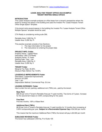
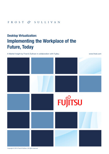
Network Virtualization inMulti-tenant Datacenters4 Forwarding State ComputationIn this section, we describe how NVP computes the forwarding state for the virtual switches. We focus on asingle controller and defer discussion about distributing the computation over a cluster to the following section.4.1 Computational Structure of ControllerThe controller inputs and outputs are structured as depicted in Figure 3. First, hypervisors and gateways providethe controller with location information for vNICs over the configuration protocol (1), updating this informationas virtual machines migrate. Hypervisors also provide the MAC address for each vNIC. Second, service providersconfigure the system through the NVP API (see the following section) (2). This configuration state changes asnew tenants enter the system, as logical network configuration for these tenants change, and as the physicalconfiguration of the overall system (e.g., the set of managed transport nodes) changes.Figure 3. Inputs and outputs to the forwarding state computation process.Based on these inputs the controller computes forwarding state (3), which is pushed to transport nodes viaOpenFlow and the OVS configuration protocol. OpenFlow flow entries model the full logical packet forwardingpipeline, as discussed in the previous section. The controller also computes OVS configuration database entriesconsisting of the tunnels connecting hypervisors, gateways, and service nodes, and any local queues andscheduling policies.4.2 Computational ChallengeThe input and output domains of the controller logic are complex: in total, the controller uses 123 types of inputto generate 81 types of output. The input state is large, being proportional to the size of the MTD, and changesfrequently as VMs migrate, tenants enter and exit, and tenants reconfigure their logical networks.The controller needs to react quickly to these input changes. Given the large total input size and frequent, localizedinput changes, a naïve implementation that reruns the full input-to-output translation on every change would becomputationally inefficient. Incremental computation allows us to recompute only the affected state and pushthe delta down to the network edge. We first used a hand-written state machine to incrementall
A tenant interacts with a network (both its home network, and the network in the MTD) in two ways: the tenant's endpoints (e.g., hosts and/or VMs) send packets, and the tenant's control plane (e.g., routing protocols, manual configuration) configures network elements (e.g., switches and routers). A service provider's network consists